
ABSTRACT
Holey graphene (hG), also called graphene nanomesh, is a structural derivative of graphene. hG is formed by removing a large number of atoms from the graphitic plane to produce holes distributed on and through the atomic thickness of the graphene sheets. These holes, sometimes with abundant functional groups around their edges, impart properties that are uncommon to intact graphene but advantageous toward various applications. In this review, strategies to prepare hG and the related applications that take advantage of the unique structural motif of these materials are discussed. Prospects are then given for this emerging class of graphene derivatives.
GRAPHICAL ABSTRACT
IMPACT STATEMENT
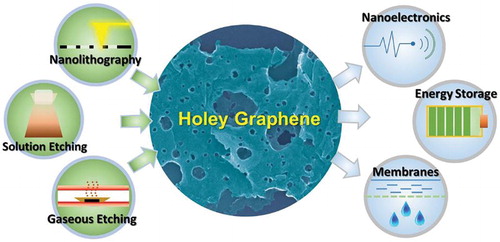
Holey graphene is a novel class of graphene derivative that has in-plane porosity. It outperforms intact graphene in many applications such as nanoelectronics, sensors, energy storage, and membranes.
1. Introduction
An ideal graphene sheet is a perfect two-dimensional graphitic crystal consisting of only one layer of carbon atoms. Since its first isolation in 2004 [Citation1], graphene has attracted applications in the fields of electronics, sensors, composites, and energy storage due to its high surface area, high electrical and thermal conductivity, excellent mechanical strength, thermal and chemical stability, and the ability to be modified to introduce diverse chemical functionalities [Citation2,Citation3].
In the last decade, many methods have been established to prepare monolayer or few-layered graphene sheets [Citation4,Citation5]. The highest quality sheets come from mechanical exfoliation (the ‘Scotch tape’ method), which can generate large area sheets with very low defect density [Citation1]. However, this method is not scalable as it provides only a few sheets on supported substrates. The most scalable method for applications, such as composites and energy storage, is oxidation and exfoliation of graphite to generate graphene oxide (GO), which can be reduced to restore its graphitic structure [Citation6]. The graphene thus produced, called reduced graphene oxide (rGO), has defects, but can be prepared routinely in gram quantities in laboratories, and has recently been industrialized to ton quantities [Citation7]. Other methods, such as chemical vapor deposition (CVD) growth [Citation8] and liquid exfoliation of graphite [Citation9], have also been industrialized and provided graphene materials with qualities and quantities in between the above two extremes and give specific property combinations required for some applications [Citation10].
While mechanically exfoliated graphene sheets are usually of high atomic order, as-produced graphene sheets from many other methods always contain defects from atomic to nanoscale. At first glance, it would seem undesirable to have defects on graphene sheets, since defects would be detrimental to mechanical strength and electrical conductivity. However, due to quantum confinement effects, structural defects at the nanoscale impart unique physical and chemical properties to nanosized objects, thereby affording desirable properties for some applications [Citation11–13]. For example, the presence of defects may allow more facile attachment of functional groups, which may affect other properties such as processing characteristics or interaction with other materials including polymer or biological agents, making these functionalized graphene materials more beneficial in polymeric composites and biological applications [Citation3].
This review discusses a unique category of defective graphene material called ‘holey graphene’ (hG, also called ‘graphene meshes’ or ‘graphene nanomeshes’). For hG, nanometer-sized or even larger (‘mesoscale’) holes are intentionally introduced to afford significant gains for various applications. For example, the creation of a large number of holes can result in quantum confinement of the remaining graphitic structure, which leads to significant changes to electronic properties of the nanosheets [Citation14,Citation15]. For sensing applications, the abundant hole-edge functional groups provide many more active sites and can increase the sensitivity or response toward targeted chemical or biological species [Citation16]. In energy storage applications, the presence of holes may allow facile cross-plane ion transport, enabling high-charge-/discharge-rate devices [Citation17–19]. Herein, various strategies to prepare hG are systematically presented, followed by a discussion on several representative applications that are enabled by the structural motifs of hG. Finally, some prospects for this emerging class of graphene structural derivatives are summarized.
2. Preparation of holey graphene
2.1. High-precision and high-fidelity methods
The initial curiosity toward intentionally introducing structural vacancies on graphene surfaces evolved from two considerations [Citation20]:
Can a graphene sheet retain its mechanical integrity when large (nanometers or larger) defects or holes are introduced?
How would the electronic properties of graphene change when quantum confinement is induced by the sculpturing of the conjugated structure?
2.1.1. Electron or ion-beam bombardment
To produce holes through a thin layer of material in the macroscopic world, the use of mechanical force is a straightforward choice. One approach to obtain holes through graphene sheets was achieved by high-energy bombardment with electrons or ions. For example, the electron beam in a transmission electron microscope (TEM) was used to drill nanometer-sized holes in graphene sheets, while the entire process was monitored via real-time imaging. In one of the first efforts, Fischbein and Drndic suspended mechanically exfoliated multilayer graphene sheets over a hole in an SiNx membrane, and condensed the imaging electron beam to the nanometer level [Citation20]. The energy of the electron beam was sufficient to ablate through the graphene layers, forming pores of circular shapes (). By controlling the position and/or movement of the electron beam, pores of different shapes (circular or line-shaped) and arrays of pores were prepared at a rate of a few seconds per hole. For defect-free graphene, the threshold electron beam energy needed for hole ablation was ∼80 keV, with the carbon displacement cross-section rapidly rising with increasing energy [Citation23]. However, the presence of defects, doped atoms, and contaminations significantly reduced the ablation energy threshold.
Figure 1. TEM images of a suspended graphene sheet (a) before and (b) after a nanopore is made by electron beam ablation. (c) Higher magnification image of the nanopore. (d) Multiple nanopores made in close proximity to each other. Scale bars are 50, 50, 2, and 10 nm, respectively. Reproduced from Ref. [Citation20] with permission from AIP Publishing LLC.
![Figure 1. TEM images of a suspended graphene sheet (a) before and (b) after a nanopore is made by electron beam ablation. (c) Higher magnification image of the nanopore. (d) Multiple nanopores made in close proximity to each other. Scale bars are 50, 50, 2, and 10 nm, respectively. Reproduced from Ref. [Citation20] with permission from AIP Publishing LLC.](/cms/asset/625e5bfc-1b00-4e8d-bee4-4393e1627264/tmrl_a_1271047_f0001_b.gif)
High-energy ion beams can also ablate through the graphene layers. In the report by Standop et al. [Citation24], a graphene monolayer supported on an Ir(111) substrate was subjected to 5 keV Xe+ irradiation at room temperature. Interestingly, with an off-normal incident angle of 75°, each incident ion left a track of a few nanometer-sized holes along the impacting direction. In an ‘interface channeling’ model, it was proposed that the incident ions might have penetrated through the top graphene layer, and reflected between the metallic substrate and the graphene sheet, resulting in multiple hole openings on the sheet. By controlling the irradiation energy and flux, graphene nanomesh with well-spaced holes was created with the hole-distribution periodicity regulated by the incident irradiation angle and the graphene–substrate distance.
The above electron and ion beam of drilling processes are highly localized with high precision. Obviously, it is prohibitively time-consuming if a large array of holes is to be drilled with such techniques. Although these methods are not scalable, they enabled some interesting sensing experiments in which ionic current blockage was detected while passing molecules, such as DNA, through the holes [Citation25–27]. More details will be discussed in Section 3.3.
2.1.2. Nanolithographic methods
Compared to electron beam drilling, nanolithographic etching is a high-throughput method to produce hG with periodic arrays of holes and narrow hole-size distributions [Citation28]. A typical nanolithographic etching process consists of several common steps:
Graphene sheets are deposited or synthesized on a substrate
A porous template or mask is prepared to cover the top surface of the graphene sheets
An etching process is conducted
The template or mask is removed to yield hG products
This technique was first independently reported in 2010 by Bai et al. [Citation14] and Kim et al. [Citation15] who synthesized hG (‘graphene nanomeshes’) with highly ordered mesh-like structures using block copolymer lithography, which is a multi-step nanolithographic method using a block copolymer as the template (). Both groups used poly(styrene-block-methyl methacrylate) [P(S-b-MMA)], a thin film that exhibits hexagonally packed cylindrical poly(methyl methacrylate) (PMMA) domains in the PS matrix. After coating the graphene with a sacrificial SiOx layer followed by the block copolymer, PMMA domains were removed via UV exposure, and the template was developed using glacial acetic acid. A reactive-ion etch (RIE) process was then used followed by an oxygen plasma etch to drill through the SiOx layer, and then the underlying graphene sheet. Removing the SiOx layer resulted in hG with highly ordered hexagonally packed holes inherited from the block copolymer. It is possible to tune the periodicity of the hexagonal packing by using different molecular weights of the block copolymer. At the same periodicity, using the same block copolymer, over-etching resulted in larger holes and smaller ‘neck widths’, i.e. the widths of the graphene structure between adjacent holes (eg ∼9–15 nm at 39 nm periodicity). The concept of the neck width is important for the hG materials from nanolithographic methods because their primary application is for FET devices in which hGs mimic the behavior of graphene nanoribbons. The widths of graphene nanoribbons are directly related to their electronic properties. Similarly, the neck width is one of the crucial factors for the hG-based FET device performances.
Figure 2. Schematic depiction of the fabrication of nanoperforated, highly oriented pyrolitic graphene (HOPG), or hG, using block copolymer lithography and the corresponding top-down scanning electron microscopy (SEM) images of (a) vertically oriented PMMA cylinders in a block copolymer thin film obtained by thermal annealing, (b) residual PS honeycomb template obtained after selective PMMA removal with UV irradiation, (c) etched structures after O2 followed by CHF3 + O2 plasma RIE resulting in the etching of the random copolymer mat and the oxide buffer layer, respectively, and (d) nanoperforated HOPG resulting from the final O2 plasma RIE and the removal of the oxide buffer by HF solution. Scale bars = 200 nm. Reproduced from Ref. [Citation15] with permission from American Chemical Society.
![Figure 2. Schematic depiction of the fabrication of nanoperforated, highly oriented pyrolitic graphene (HOPG), or hG, using block copolymer lithography and the corresponding top-down scanning electron microscopy (SEM) images of (a) vertically oriented PMMA cylinders in a block copolymer thin film obtained by thermal annealing, (b) residual PS honeycomb template obtained after selective PMMA removal with UV irradiation, (c) etched structures after O2 followed by CHF3 + O2 plasma RIE resulting in the etching of the random copolymer mat and the oxide buffer layer, respectively, and (d) nanoperforated HOPG resulting from the final O2 plasma RIE and the removal of the oxide buffer by HF solution. Scale bars = 200 nm. Reproduced from Ref. [Citation15] with permission from American Chemical Society.](/cms/asset/06329bef-2211-46ae-8d2b-beb136d22b86/tmrl_a_1271047_f0002_c.jpg)
Instead of using a block copolymer, Liang et al. [Citation34] used nanoimprint templates to physically impose periodic hole arrays onto the PS-based resist coating, followed by similar RIE etching procedures to produce substrate-supported hG with highly ordered holes.
AAO has vertically aligned hexagonal arrays of cylindrical nanochannels, and has been widely used for the template formation of various one-dimensional nanostructures [Citation35]. Zeng et al. [Citation29] utilized AAO as a mask along with a protection layer of PMMA to etch large area Si/SiO2 substrate-supported rGO with O2 plasma. The hole dimensions and neck widths of the hG were largely determined by those in the AAO template [Citation29,Citation36]. More structural tunability was achieved by sputtering Pt onto AAO to create porous Pt masks of various neck widths, which were then used as direct templates for hG formation [Citation37].
Monodisperse colloidal nanoparticles were also used as templates for hG preparation. As shown in , Sinitskii and Tour [Citation38] spread a monolayer of silica nanoparticles of a given diameter onto graphene that was first covered with a protective silica layer. The stack was subjected to RIE to partially etch the silica nanoparticles to a desired diameter, partially exposing the graphene/protection layer underneath. Subsequently, another protection layer (Au) was evaporated onto the stack, followed by removal of the silica nanoparticles and a second RIE step to carve holes in the graphene. All protection layers were then removed to afford hG. The key to achieving highly ordered hole structures in nanosphere lithography is to use highly monodisperse nanoparticles. Colloidal PS nanoparticles with well-established preparation procedures were also excellent choices as lithographic templates for hG preparation [Citation39–41]. The nanosphere lithography yielded hGs with larger hole diameters (>100 nm) so this method was complementary to the block copolymer method. With excellent electronic properties, the FET devices based on hG from nanosphere lithography were used as chemiresistor sensors that exhibited superior response to both electron-donating and electron-withdrawing gaseous species such as NO2 and NH3 [Citation39].
Figure 3. Nanosphere lithography for hG. Reproduced from Ref. [Citation38] with permission from American Chemical Society.
![Figure 3. Nanosphere lithography for hG. Reproduced from Ref. [Citation38] with permission from American Chemical Society.](/cms/asset/8f1b7a33-cf24-4307-9fe8-609277601d23/tmrl_a_1271047_f0003_c.jpg)
Conventional photolithographic methods were employed to prepare large area ‘graphene meshes’ with periodicity on the order of tens of micrometers [Citation31]. E-beam lithography was used to prepare meshes with hole widths of a few micrometers [Citation42]. However, such graphene meshes are prepared from thin films, not individual graphene sheets, and are not a graphene structural derivative but modified films. An exception was a recent report which demonstrated that the use of interferometric lithography could reduce the neck width of the photoresist to 70 nm [Citation33]. With 80 s of O2 plasma etching, the neck widths of the exceptionally large area graphene mesh could reach as narrow as 10 nm, a dimension relevant to the structural modification of individual graphene sheets. The method was used to prepare wafer-scale samples over 1 × 1 cm2 with a periodicity of 150–200 nm, which exhibited reasonable FET characteristics that were comparable to hG samples from other nanolithographic techniques (). A slight drawback was that the residual photoresist could not be fully removed, leaving ∼15–20 nm coatings on the product. Nevertheless, the Raman spectra of the graphene structures were readily detected. The locations with 10 nm neck width exhibited enhanced D-band attributed to the increased edge-to-surface atomic ratios.
Table 1. Comparison of dimensions and electronic properties of hGs fabricated by different techniques.
2.1.3. Templated growth
Bottom-up growth of graphene using CVD approaches with gaseous carbon precursors has been extensively studied in recent years [Citation3,Citation8]. In a typical CVD growth process, a gaseous carbon feedstock, such as methane, is introduced into a heated furnace and decomposes on the surface of a supporting smooth metallic (typically Cu or Ni) substrate that has extremely low carbon solubility, thereby allowing the two-dimensional growth of graphene crystals. In the nanolithography approaches for hG discussed in the previous section, graphene is first grown or deposited onto a substrate covered with the nanotemplates, and then selectively etched. In the templated growth of hG, the nanotemplates are first deposited onto an active substrate, followed by CVD growth of graphene. The templates served as the inert islands blocking the otherwise continuous graphene formation, creating well-defined patterns.
In one of the first demonstrations, Safron et al. [Citation44] patterned aluminum oxide (Al2O3) via e-beam and block copolymer lithography as the inert templates (or ‘barriers’) on Cu foil. Various shapes and patterns of barriers were fabricated, and graphene was subsequently grown via CVD on the exposed Cu at 1000°C. The oxide barriers were then removed, leaving well-defined patterned graphene. Block copolymer lithography allowed the deposition of a hexagonal array of Al2O3 nanoparticles of 16 nm in diameter with a periodicity of 41 nm. Remarkably, the holes after graphene growth were only ∼1 nm larger in diameter than the nanoparticle templates (neck width ∼24 nm), suggesting near-atomic precision of the barrier function at the given growth conditions. The nucleation density of graphene on the nanoparticle-patterned Cu was lower than unimpeded growth on bare Cu, but the shape of the crystallites remained hexagonal. Multiple domains seamlessly zipped together to form a large-area, continuous high-quality hG film. Compared to hG from top-down (ie using intact graphene as the starting material) lithography methods, the Raman spectra of the CVD-grown hG exhibited much lower D-band intensity, suggesting well-defined hole edges where the barriers terminated growth. Similar findings were reported by Wang et al. [Citation43], who used a closely packed colloidal PS nanoparticle monolayer to pattern SiO2 islands that served as the templates/barriers for CVD growth of hG with neck widths of 65–75 nm (). This bottom-up, nanosphere-templated growth method is analogous to the top-down nanosphere lithography for hG formation discussed in the previous section () [Citation38].
Figure 4. Nanosphere-templated hG growth. Reproduced from Ref. [Citation43] with permission from Nature Publishing Group.
![Figure 4. Nanosphere-templated hG growth. Reproduced from Ref. [Citation43] with permission from Nature Publishing Group.](/cms/asset/2e27c5e6-1f2b-4c2a-b08e-2f8ca80e9339/tmrl_a_1271047_f0004_c.jpg)
Using AAO as the template, Jung et al. [Citation37] sputtered a thin Au layer and transferred it onto an SiO2 wafer for graphene growth. The morphology of the AAO channels led to hG films with neck widths as small as 19 nm. In a related gram-scale bottom-up growth method, highly porous MgO crystalline platelets were used as the growth template for graphene [Citation45]. However, graphene growth was not planar because it followed the contours of the porous MgO templates. Therefore, these products were not exactly hG, but more precisely a type of porous graphene with continuous graphitic structures.
2.2. Scalable methods
For many non-electronic applications such as composites and energy storage, large quantities of active materials are needed. The high-precision methods for hG synthesis discussed in the previous section do not usually provide enough material for such purposes. To prepare bulk quantities of hG, the first step is to obtain enough graphene starting material. As discussed in the Introduction, one of the most convenient and scalable methods to prepare graphene is via GO nanosheets produced by liquid-phase oxidation and exfoliation of graphite. The majority of the scalable hG preparation methods reported thus far started with either GO or its reduced form (rGO). The abundant defect sites in GO or rGO from the highly oxidative synthesis conditions usually serve as the main seeding sites for the hole growth to form hG. It should also be noted that most scalable methods that are used to process GO into hG are also applicable to substrate-supported graphene sheets, although the conditions must be adjusted to avoid over-oxidation.
2.2.1. Liquid-phase oxidation
Liquid-phase oxidation methods using conventional wet chemistry are popular in hG synthesis. In many examples, the direct products from liquid-phase oxidation methods were holey graphene oxide (hGO) nanosheets, the highly oxidized and water-soluble form of hG. hGO can be reduced to more electrically conductive hG via reduction methods applicable to GO. The comparison of hGO vs. hG is highly analogous to that of GO vs. rGO.
In Hummer’s method in which graphite is oxidized and exfoliated by acidified KMnO4 [Citation4–6], the reaction mixture is typically heated to 40–70°C for a few hours. Alternatively, using microwave irradiation with acidified KMnO4 produced GO in as little as 30 s [Citation46]. Interestingly, only slightly longer exposure (40 s) resulted in controlled over-oxidation and yielded hGO. The presence of both strong mixed acids (H2SO4:HNO3 = 4:1) and KMnO4 oxidants was critical to the hGO formation. The mixed acids introduced nitronium ions, which attacked both defect and graphitic carbons to create defects on the graphite, while KMnO4 preferentially reacted with existing defects facilitating hole formation. Consequently, the use of only mixed acids without KMnO4 resulted in small graphene pieces [Citation46]. However, with GO as the starting material, KMnO4 alone was sufficient to form hGO with microwave energy [Citation47]. In a related report, liquid exfoliated graphene (from organic solvent sonication of graphite [Citation9]), which has fewer defects than GO, was used as the starting material for hG via the use of room temperature KMnO4 solution, followed by treatment with hot HCl [Citation48]. The oxidation extent was less because of the lack of a strong oxidizing acid; the hG product had few defects, and remained in a non-oxidized form with relatively low oxygen content.
Concentrated HNO3 was another reagent used for hG/hGO synthesis. In fact, the first successful large-scale hGO syntheses were by Kung and coworkers, who used 1 h bath sonication to process an aqueous mixture of GO and concentrated HNO3, leading to hGO with wide hole-size distributions [Citation17,Citation49]. Increasing the amount of HNO3 resulted in larger holes with a higher extent of oxidation. In comparison to GO, hGO had more carbonyl and carboxylate functional groups. The high water solubility of hGO made it readily processable, like the parent GO. For example, by following the typical method of preparing ‘GO paper’ [Citation50], hGO was vacuum filtered to form a free-standing membrane (‘HGO paper’) that was reduced into ‘rHGO paper’ (ie hG paper) ().
Figure 5. Schematic drawing (not to scale) of the introduction of in-plane pores into GO and the subsequent filtration into an HGO paper. The thermal reduction of GO sheets with in-plane porosity and removal of water molecules from the interlayers result in a three-dimensional network with interconnecting graphitic domains that retain high electrical conductivity and structural integrity and disordered porous graphene regions that provide interplane diffusion channels (rHGO). Li ions can diffuse throughout the structure rapidly through the in-plane pores and interplane channels. The interlayer spacing between graphene sheets is greatly exaggerated. The digital image shows a coin cell-size rHGO paper. Reproduced from Ref. [Citation49] with permission from American Chemical Society.
![Figure 5. Schematic drawing (not to scale) of the introduction of in-plane pores into GO and the subsequent filtration into an HGO paper. The thermal reduction of GO sheets with in-plane porosity and removal of water molecules from the interlayers result in a three-dimensional network with interconnecting graphitic domains that retain high electrical conductivity and structural integrity and disordered porous graphene regions that provide interplane diffusion channels (rHGO). Li ions can diffuse throughout the structure rapidly through the in-plane pores and interplane channels. The interlayer spacing between graphene sheets is greatly exaggerated. The digital image shows a coin cell-size rHGO paper. Reproduced from Ref. [Citation49] with permission from American Chemical Society.](/cms/asset/f5b03e7c-2605-4aa2-b529-b363a077aeaf/tmrl_a_1271047_f0005_c.jpg)
Chemically reduced GO was also oxidatively etched by refluxing in concentrated HNO3 for a prolonged period of time (4–11 h) [Citation51]. The resultant hGs had pore sizes of 10–40 nm (4 h reflux) or >40 nm (9 h reflux); both had high pore densities. However, 11 h of reflux resulted in over-oxidation and cleaved the rGO sheets into small pieces. Controlled oxidation removed the defect carbons and formed holes on rGO sheets, but the resulted hG products had much lower oxygen content than typical GO and hGO. Interestingly, the products still had small enough zeta-potentials (−36 to −46 mV) to be stable in aqueous solution, and were readily soluble in water and processable using aqueous methodologies. The solubility was most likely rendered by the abundant hole-edge-attached, oxygen-containing functional groups formed with the holes.
Milder oxidation reagents were also used for hG/hGO synthesis, but they would require more demanding conditions, or the use of catalysts. In a typical Hummer’s method for GO synthesis, H2O2 is often used to remove excess KMnO4 at the end of the oxidation reaction and is generally considered ineffective at oxidizing the graphitic surface. However, Xu et al. demonstrated that diluted H2O2 oxidized GO in aqueous solutions forming hG, but only under hydrothermal conditions [Citation19,Citation52]. For example, at 180°C for 6 h, the GO sheets transformed into an interconnected hydrogel network of hG sheets via self-assembly () [Citation19]. After reduction and freeze-drying steps, foam-like hG monoliths were obtained. The hG foams were lightweight and highly compressible, and exhibited high surface area and excellent electrical conductivity. At a lower hydrothermal reaction temperature (100°C for 4 h) where a hydrogel was not formed, water-soluble hGO was found to be the product [Citation52]. The hGO solutions were subsequently processed into hydrogels or papers for energy storage applications [Citation19,Citation52].
Figure 6. Preparation and structural characterization of hG foams (HGF). (a) Schematic illustration of the preparation process of HGFs and HGF films. (b) A photograph showing a free-standing HGF. (c) SEM image of interior microstructures of HGFs. Scale bar = 1 µm. (d) TEM image of hG sheets in HGFs. Scale bar = 10 nm. (e) TEM image of non-hG sheets in GFs for comparison. Scale bar = 10 nm. (f) A photograph showing HGFs before and after mechanical compression with the flexibility of the compressed HGF film shown in the inset. (g) Cross-sectional SEM image of the compressed HGF film. Scale bar = 1 µm. Reproduced from Ref. [Citation19] with permission from Nature Publishing Group.
![Figure 6. Preparation and structural characterization of hG foams (HGF). (a) Schematic illustration of the preparation process of HGFs and HGF films. (b) A photograph showing a free-standing HGF. (c) SEM image of interior microstructures of HGFs. Scale bar = 1 µm. (d) TEM image of hG sheets in HGFs. Scale bar = 10 nm. (e) TEM image of non-hG sheets in GFs for comparison. Scale bar = 10 nm. (f) A photograph showing HGFs before and after mechanical compression with the flexibility of the compressed HGF film shown in the inset. (g) Cross-sectional SEM image of the compressed HGF film. Scale bar = 1 µm. Reproduced from Ref. [Citation19] with permission from Nature Publishing Group.](/cms/asset/08f3f644-17a4-41b0-89c6-d6dc67bdf67f/tmrl_a_1271047_f0006_c.jpg)
Alternatively, Au nanoparticles catalyzed the H2O2 oxidation of rGO into hG via UV photolysis [Citation53]. It was proposed that the Au nanoparticles catalyzed both the decomposition of H2O2 into ·OH (hydroxyl radical) and the oxidation of rGO by ·OH (more info in Section 2.2.4). Hole-edge functionalities, especially carboxylic acid moieties, made some hG products excellent candidates to detect trace H2O2, with their sensitivity comparable to the widely adopted biosensing approach using horseradish peroxidase (HRP) [Citation51]. Interestingly, HRP, a common oxidative enzyme molecule, in the presence of H2O2 also catalyzed the oxidation of GO to form holes on graphene sheets after a few days of incubation [Citation54]. However, the same procedure was ineffective toward rGO, presumably due to conformational restrictions that induced insufficient activity of the enzyme after binding to the less hydrophilic graphitic surfaces of rGO.
2.2.2. Gaseous-phase etching
As-prepared graphene sheets, especially thermally reduced GO (t-rGO) from rapid heating of GO to achieve simultaneous reduction and exfoliation [Citation55], contain abundant intrinsic point defects. These point defects can originate from the parent GO due to the oxidative synthesis conditions, or may be formed during the rapid heating due to the quick release of gaseous byproducts such as CO2. Recently, several groups, including our team, built upon this aspect of the thermal exfoliation process to produce hG using controlled partial air oxidation [Citation18,Citation56–60]. These processes were typically carried out in air without solvents or other chemical agents, making them the most facile methods for scalable hG production using GO or rGO as the starting material.
In one example of gaseous phase etching, a commercially obtained t-rGO powder was subjected to a single-step air oxidation near its weight-loss threshold (∼400–500°C) () [Citation18,Citation56]. Both temperature and heating duration were varied, and hG was formed at a temperature as low as 390°C with a heating duration as short as 1 h [Citation56]. At the more benign end of synthesis conditions (ie lower temperature and/or shorter heating duration), defect carbons were selectively oxidized and gasified, forming holes with diameters of a few nanometers on the graphene sheets. Interestingly, a further increase in temperature and heating duration did not significantly increase the hole size, but the electrochemical double layer capacitance of the products exhibited dramatic improvement (approximately twofold). Despite the presence of abundant holes, the D/G ratios in the Raman spectra of hG products remained similar to the starting t-rGO. The Brunauer–Emmett–Teller (BET) surface area of the hG products increased slightly, while the fraction of mesopores increased significantly. Further structural characterizations revealed that both the increased population of oxygen-containing functional groups located around the hole edges and the increased mesopore fraction were likely the main causes for the observed capacitance improvement. It was proposed that, after removal of defective carbon during initial heating, further thermal oxidation started to occur on graphitic carbons, resulting in the formation of hole-edge functional groups and mesopores that were critical for electrochemical energy storage [Citation56].
Figure 7. (a) Schematic of the scalable synthesis of the hG sheets, (b) digital photo of the as-synthesized hG powder in bulk, and (c) Raman spectra comparison for hG obtained at 480°C/3 h and the starting graphene (t-rGO). Reproduced from Ref. [Citation18] with permission from American Chemical Society.
![Figure 7. (a) Schematic of the scalable synthesis of the hG sheets, (b) digital photo of the as-synthesized hG powder in bulk, and (c) Raman spectra comparison for hG obtained at 480°C/3 h and the starting graphene (t-rGO). Reproduced from Ref. [Citation18] with permission from American Chemical Society.](/cms/asset/be3531d7-7317-4178-a04f-f640a4bf318a/tmrl_a_1271047_f0007_c.jpg)
Earlier efforts at rapid thermal exfoliation of GO were purposely carried out in an inert atmosphere to avoid the formation of defects [Citation55]. Such thermally exfoliated graphene material is intrinsically a ‘holey’ graphene material, although in most cases the holes are in the size domain of point defects (ie only a few atoms missing). By carrying out the thermal exfoliation of GO in air, Chang and coworkers successfully obtained hG materials with through-thickness holes () [Citation57–59]. Here, the oxygen in the air aided the mechanical punctuation from rapid expansion of gaseous products, arising from oxidation of defect site functional groups, to form nanometer-sized or even larger holes on graphene sheets. Note that mostly point defects were formed upon rapid heating in inert atmosphere. In Chang et al.’s experiments, it was also demonstrated that a high heating rate was critical in the hole formation. Although slow heating in air also resulted in exfoliated and reduced graphene, few or no holes were present in the products. A lower heating temperature of 300°C was sufficient to introduce holes while preserving abundant oxygen functional groups that are beneficial for electrochemical energy storage. Higher temperatures with a high heating rate also produced hG, but the oxygen functional groups were mostly removed.
Figure 8. Schematic illustration for the ultra-rapid heating of GO powder to obtain and collect fluffy hG products with much increased volume. Reproduced from Ref. [Citation57] with permission from Elsevier.
![Figure 8. Schematic illustration for the ultra-rapid heating of GO powder to obtain and collect fluffy hG products with much increased volume. Reproduced from Ref. [Citation57] with permission from Elsevier.](/cms/asset/392578f4-62c2-44f2-a210-550e3f96c6d8/tmrl_a_1271047_f0008_c.jpg)
The strategy of direct thermal exfoliation in air for hG production could be pushed one step back in the GO production process to the stage where graphite was effectively oxidized (eg using NaClO3 and fuming HNO3) but not yet exfoliated into GO (usually achieved in the presence of acidic KMnO4). Rapidly heating graphite oxide in air at 300°C for 30 min also resulted in the formation of hG [Citation60]. Compared to graphite oxide, these hG materials exhibited increased surface area and mesopore population, restoration of the graphitic network, and reduced oxidation extent. The X-ray photoelectron spectroscopy (XPS) data suggested that these materials had concentrations of oxygen-containing functional groups that are comparable to those in hG produced by other partial air oxidation methods discussed above.
Gaseous etching techniques were also applied to substrate-supported graphene nanosheets. For example, Han and coworkers found that steam was a mild enough etchant to introduce in-plane pores on GO sheets supported on SiO2/Si substrates or copper TEM grids [Citation16]. The reaction was carried out in a sealed vessel at 200°C, and pores of 2–40 nm were found. Air oxidation of substrate-supported GO could even proceed under room temperature with UV light irradiation [Citation61]. Oxygen-rich regions on the GO sheets were found to be the most susceptible to further oxidation to form holes.
2.3.3. Chemical activation
Activated carbon (AC) is a high-surface-area material that has been industrialized and is commonly used as an adsorbent and as an electrode [Citation62,Citation63]. A common method to produce AC is to chemically treat a carbon stock with certain corrosive chemicals such as potassium hydroxide (KOH) followed by carbonization. Ruoff and coworkers adopted a similar strategy and used KOH to treat microwave-exfoliated GO (MEGO), a type of reduced GO from a rapid microwave heating process, and generated a high-porosity activated-graphene material dubbed ‘a-MEGO’ [Citation64]. Activated MEGO graphene sheets contain in-plane pores that are through the sheet thickness, a key feature of hG materials that are surveyed in this review. However, it should be noted that the surface area values and electrochemical properties of a-MEGO seem to be dictated more by the three-dimensionally interconnected pores than the two-dimensional holes that are similarly present in other typical hG materials.
In the first reported experiments on a-MEGO in 2011 () [Citation64], MEGO was first impregnated with a concentrated (7 M) KOH solution. The dried mixture was then treated at 800°C for 1 h under argon, followed by washing to remove the excess base. A final high-temperature-annealing step resulted in reducing the oxygen functional group content in a-MEGO materials. In comparison, many as-prepared hG materials from the liquid-phase or gaseous-phase oxidative etching processes contain abundant oxygen functional groups if no annealing step is applied. Nevertheless, the a-MEGO products exhibited pore sizes ranging from <1 to 10 nm and BET surface area values, as high as 3100 m2/g. The theoretical surface area of graphene is only 2630 m2/g. The ultra-large surface area was attributed to the highly interconnected micropores and mesopores generated during the KOH etching process. Similar KOH-activation processes were also successfully applied to t-rGO powder [Citation64], GO films [Citation65], and even ‘crumpled’ GO [Citation66]. Activated graphene from ‘crumpled’ GO not only exhibited micropores and mesopores that are typical for other a-MEGO materials, but also contained macropores as a result of the aerosol spray drying process that introduced the ‘crumpled’ morphology. Their hierarchical pore structure makes these materials excellent candidates for electrochemical energy storage.
Figure 9. (A) Schematic showing the microwave exfoliation/reduction of GO and the following chemical activation of MEGO with KOH that creates pores while retaining high electrical conductivity. (B) Low magnification SEM image of a three-dimensional a-MEGO piece. (C) High-resolution SEM image of a different sample region that demonstrates the porous morphology. (D) Annular dark-field scanning transmission electron microscopy image of the same area as (C), acquired simultaneously. As seen, a-MEGO contains micro- and mesopores with a distribution of sizes between ∼1 and ∼10 nm. (E) High-resolution phase contrast electron micrograph of the thin edge of an a-MEGO chunk, taken at 80 kV. There is a variation in focus across the image because of the sloped nature of the sample and changes in sample thickness. The image shows the presence of a dense network of nanometer scale pores surrounded by highly curved, predominantly single-layer carbon. (F) Exit wave reconstructed high-resolution transmission electron microscopy image from the edge of a-MEGO. The in-plane carbon atoms are clearly resolved, and a variety of n-membered carbon rings can be seen. Substantial curvature of the single-carbon sheets is visible, with the in-plane crystallinity being preserved. Reproduced from Ref. [Citation64] with permission from The American Association for the Advancement of Science.
![Figure 9. (A) Schematic showing the microwave exfoliation/reduction of GO and the following chemical activation of MEGO with KOH that creates pores while retaining high electrical conductivity. (B) Low magnification SEM image of a three-dimensional a-MEGO piece. (C) High-resolution SEM image of a different sample region that demonstrates the porous morphology. (D) Annular dark-field scanning transmission electron microscopy image of the same area as (C), acquired simultaneously. As seen, a-MEGO contains micro- and mesopores with a distribution of sizes between ∼1 and ∼10 nm. (E) High-resolution phase contrast electron micrograph of the thin edge of an a-MEGO chunk, taken at 80 kV. There is a variation in focus across the image because of the sloped nature of the sample and changes in sample thickness. The image shows the presence of a dense network of nanometer scale pores surrounded by highly curved, predominantly single-layer carbon. (F) Exit wave reconstructed high-resolution transmission electron microscopy image from the edge of a-MEGO. The in-plane carbon atoms are clearly resolved, and a variety of n-membered carbon rings can be seen. Substantial curvature of the single-carbon sheets is visible, with the in-plane crystallinity being preserved. Reproduced from Ref. [Citation64] with permission from The American Association for the Advancement of Science.](/cms/asset/546c8140-a61d-48e9-8010-d5a6aca87538/tmrl_a_1271047_f0009_c.jpg)
Rather than heating at high temperature, KOH etching of GO was conducted at ambient conditions with 30 h of ball-milling using a planetary mill [Citation67–69]. Three-dimensional porous structures were also found in the final hG products, which exhibited somewhat lower BET surface area values (∼800 m2/g) than typical a-MEGO materials. Room temperature etching with aqueous NaOH solution was successful with silica-coated GO [Citation70]. The treatment with NaOH not only removed the silica coating, but also simultaneously caused perforation of the graphene sheet.
2.2.4. Guided etching with catalytic or reactive nanoparticles
Many methodologies have been developed to deposit inorganic (eg metal or metal oxide) nanoparticles onto the large lateral surface of graphene sheets [Citation71]. The conductive and high-surface-area graphene substrate often enhances the performance of the nanoparticles, and the resultant nanoparticle–graphene hybrids outperform the individual components in various applications such as catalysis, sensing, and energy storage. An interesting application of the nanoparticle–graphene hybrids was their usage as precursors for hG, as discussed in this section. The well-dispersed nanoparticles on the graphene surface served as guiding sites for the chemical etching reactions, in which the nanoparticles participated either as catalysts or as active reactants. This method can be viewed as the scale-up version of the nanosphere nanolithography discussed in Section 2.1.2, even though the shape control of holes and the regularity of hole arrays were not as consistent. Another major difference was that the nanospheres in the lithographic methods function as masks, but not catalysts/reactants.
A typical procedure to prepare hG via guided etching can be described as follows (guided catalytic etching is shown in [Citation72]):
Active inorganic nanoparticles are deposited onto the graphene surface to form a nanoparticle– graphene hybrid.
The hybrid is subject to the etching reaction by a provided form of energy such as heat (thermal route) or light irradiation (photochemical route). During etching, the nanoparticles catalytically promote or chemically induce the gasification of carbon at the contact area between the nanoparticles and graphene surface, leaving behind holes that are through the graphene sheet thickness.
The nanoparticles are removed to yield hG as the final product.
Figure 10. A typical catalytic oxidative etching process to prepare hG. Reproduced from Ref. [Citation72] with permission from The Royal Society of Chemistry.
![Figure 10. A typical catalytic oxidative etching process to prepare hG. Reproduced from Ref. [Citation72] with permission from The Royal Society of Chemistry.](/cms/asset/e5dff1ec-fb05-4c91-ba60-a8835ae04211/tmrl_a_1271047_f0010_c.jpg)
Although metal-catalyzed oxidative etching of graphite dates back to the 1970s [Citation73,Citation74], it was only recently adapted for etching two-dimensional graphene sheets [Citation75] and later for hG synthesis [Citation72]. In 2012, Lin et al. [Citation72] reported the catalytic oxidative etching of graphene (), where an Ag nanoparticle–decorated graphene hybrid material was heated to 300°C in air, a temperature much lower than the thermal decomposition threshold of graphene without Ag. Most newly formed holes on the graphene sheets were associated with Ag nanoparticles, suggesting the carbon atoms that were in contact with Ag were removed during the etching (). The catalytic role of Ag was further confirmed by the XPS results, which showed that the Ag nanoparticles maintained their zero valence state after the reaction. The Ag nanoparticles were conveniently removed via acid wash or reflux to yield hG. By changing the size of the Ag nanoparticles, the hG hole sizes could be tuned in the range of about five to tens of nm. Despite the ‘defective’ appearance of these hG sheets with high densities of large holes, electron diffraction, Raman, XPS, and electron conductivity measurements, all indicated that these hG products retained the two-dimensional graphitic structure as well as a chemical composition similar to that of the parent graphene.
Figure 11. Several representative electron microscopy images of an Ag-graphene sample subjected to air oxidation at 300°C for 3 h: (a) a lower magnification SEM image showing both holes and tracks, SEM images showing areas enriched with (b) lower aspect ratio holes and (c) high-aspect ratio holes (ie tracks), (d) a TEM image at higher magnification showing the morphology of a hole. Reproduced from Ref. [Citation72] with permission from The Royal Society of Chemistry.
![Figure 11. Several representative electron microscopy images of an Ag-graphene sample subjected to air oxidation at 300°C for 3 h: (a) a lower magnification SEM image showing both holes and tracks, SEM images showing areas enriched with (b) lower aspect ratio holes and (c) high-aspect ratio holes (ie tracks), (d) a TEM image at higher magnification showing the morphology of a hole. Reproduced from Ref. [Citation72] with permission from The Royal Society of Chemistry.](/cms/asset/fac6e01b-9d30-4c23-9509-61db0c49964a/tmrl_a_1271047_f0011_b.gif)
Other noble metal nanoparticles such as Au and Pt also acted as catalysts for hG formation via thermal oxidation in air [Citation72,Citation76]. In a photocatalytic oxidation route, as mentioned in Section 2.2.1, Radich and Kamat [Citation53] used Au nanoparticles in a solution phase to catalytically oxidize rGO under UV illumination. It was proposed that the Au nanoparticles first catalyzed the oxidation of the added H2O2 to yield hydroxyl radicals. These subsequently reacted, again catalyzed by Au, with rGO to form hG that was rich in hydroxyl functional groups (). In contrast to most of the other examples in this section, in this case the Au nanoparticles were not directly anchored on the graphene sheets but used as a homogeneous catalyst in the solution process.
Figure 12. Proposed mechanism for the photoinduced reaction between RGO (ie rGO), AuNPs (ie Au nanoparticles), and H2O2. A suspension of RGO, AuNPs, and H2O2 is prepared as shown at t = 0. Upon irradiation, AuNPs catalyze photolytic production of OH• as well as OH• attack on RGO. Competitive decomposition of H2O2 to O2 leads to bubble nucleation and detachment from the RGO surface, to which we attribute the observed wrinkling of the RGO sheets. Extended irradiation leads to migration of AuNPs and creation of nanopores at various places along the RGO sheets through diffusion and/or adsorption/desorption. Reproduced from Ref. [Citation53] with permission from American Chemical Society.
![Figure 12. Proposed mechanism for the photoinduced reaction between RGO (ie rGO), AuNPs (ie Au nanoparticles), and H2O2. A suspension of RGO, AuNPs, and H2O2 is prepared as shown at t = 0. Upon irradiation, AuNPs catalyze photolytic production of OH• as well as OH• attack on RGO. Competitive decomposition of H2O2 to O2 leads to bubble nucleation and detachment from the RGO surface, to which we attribute the observed wrinkling of the RGO sheets. Extended irradiation leads to migration of AuNPs and creation of nanopores at various places along the RGO sheets through diffusion and/or adsorption/desorption. Reproduced from Ref. [Citation53] with permission from American Chemical Society.](/cms/asset/78da78f4-18b9-457d-874e-068137465560/tmrl_a_1271047_f0012_c.jpg)
In another report, Akhavan deposited GO sheets on the tips of ZnO nanorod arrays that served as photocatalyst and etching sites for the GO [Citation77]. The vertically aligned ZnO nanorods were less than 1 µm in length and 140 nm in diameter, and they led to hG with hole sizes of ∼200 nm. The same authors found that TiO2 nanoparticles were also effective in photochemical etching of GO into hG [Citation78].
Alternatively, the catalytic etching of graphene could be carried out in a reductive atmosphere. H2 etching could also induce partial carbon gasification by forming CH4 (in comparison to the CO/CO2 products from etching in air/O2). For example, Liu et al. [Citation79] successfully etched CVD-grown graphene into nanomeshes in 5% H2 at 500°C using Cu nanoparticles. There were several prior reports on nanoparticle-induced reductive etching of graphene in H2, which resulted in chirality-guided patterns instead of circular holes [Citation80,Citation81]. One might speculate that it was the reductive environment that resulted in the chirality guidance, but there was another observation that the Ag-catalyzed etching of graphene in a controlled O2 environment also followed the graphene chirality [Citation82]. Two common characteristics of the experimental conditions in these reports were the use of high-quality graphene starting material (typically from mechanical exfoliation) and prolonged etching time, which were likely among the major causes for the observed highly ordered patterned etching. In the previous example, extended thermal exposure of Ag-decorated graphene in air did result in long etched channels or trenches on graphene sheets ((c)), but the morphology was more irregular, perhaps due to the defective nature of the graphene used (t-rGO) [Citation72]. In an earlier example, rapid heating of Ag-decorated HOPG to 650°C also resulted in uneven catalytic trenching [Citation75].
There are several examples of hG syntheses where the graphene surface-anchored nanoparticles acted as the etching reactants instead of as catalysts. In the report by Fan et al. [Citation47], a solution mixture of GO and KMnO4 was subjected to microwave irradiation to form GO with surface porosity induced by high-valence Mn etching. The ‘porous GO’ (ie hGO) was subsequently reduced with hydrazine and washed with acid to afford hG. Lv et al. [Citation83] achieved similar etching chemistry by freeze-drying a GO–KMnO4 solution mixture and annealing it to 800°C in Ar, resulting in hG with holes of 40–100 nm formed around Mn3O4 nanoparticles. Zhao et al. [Citation84] prepared nitrogen-doped (N-doped) hG in the form of a lightweight foam using Fe-containing nanoparticles (). They started with GO and polymerized pyrrole onto the nanosheet surface to form a gel. After impregnating with an FeCl3 solution, the gel was heated in Ar to 850°C. At this temperature, polypyrrole decomposed to induce N-doping on graphene, while FeCl3 presumably converted into Fe2O3 that induced local etching of the graphene sheets in situ [Citation85,Citation86]. In most of these examples [Citation83–86], since an inert atmosphere was used during hole formation without additional oxidative or reductive agents, the nanoparticles must have chemically participated in the etching reactions as reagents instead of catalysts.
Figure 13. The fabrication of N-doped hG foam (N-GMF). (a) Pyrrole (Py) monomer dispersed in a GO suspension. (b) Three-dimensional polypyrrole/graphene (Py/G) obtained after hydrothermal treatment. (c) N-GMF with intercalated Fe2O3 nanoparticles. (d) N-GMF after being washed with HCl. Reproduced from Ref. [Citation84] with permission from The Royal Society of Chemistry.
![Figure 13. The fabrication of N-doped hG foam (N-GMF). (a) Pyrrole (Py) monomer dispersed in a GO suspension. (b) Three-dimensional polypyrrole/graphene (Py/G) obtained after hydrothermal treatment. (c) N-GMF with intercalated Fe2O3 nanoparticles. (d) N-GMF after being washed with HCl. Reproduced from Ref. [Citation84] with permission from The Royal Society of Chemistry.](/cms/asset/8ae4178f-2fec-4340-b322-eef3bbcdb02e/tmrl_a_1271047_f0013_c.jpg)
3. Applications of holey graphene
Target applications for hGs from high-precision production methods such as nanolithography and templated growth are mainly in nanoelectronics; for example, FETs and FET-based sensor devices. While these applications have been briefly mentioned in the earlier sections, more details can also be found in other reviews [Citation28,Citation87]. In this section, a few other key applications that take advantage of the structural motifs of hGs, especially those from scalable preparation methods, are highlighted. While the pristine graphene is useful in all of these applications, the performance of hGs is enhanced either by the presence of holes, hole-edge functional groups, or both.
3.1. Electrodes for supercapacitors and batteries
Carbon nanomaterials, especially graphene, are attractive candidates for advanced electrode materials in energy storage devices such as supercapacitors and batteries because of their excellent electrical conductivity and high surface area. However, restacking graphene sheets in their solid state significantly limits the surface area accessible by the electrolyte ions, making the actual device performance inferior to theoretical performance. A common strategy to increase accessible surface area of graphene is to introduce ‘pores’ between the nanosheets to enhance ion access. A solid-state graphene with this architecture is usually called ‘porous graphene’ and is a subject of interest for energy storage applications [Citation87,Citation88]. Although the holes on hG sheet can be considered two-dimensional pores, the concept of hG is fundamentally different. In hG, the ‘pores’ are large graphitic structural defects pertinent to the graphitic sheet structure, while in porous graphene, the pores refer to the empty spaces between the individual graphene sheets. In essence, hG is a graphene structural derivative, while porous graphene is a type of graphene assembly.
Holey graphene materials have several advantages for various energy storage applications. First, the through-plane ion transport is highly facilitated by the in-plane pores, making the ionic conduction path less tortuous compared to that in a typical electrode consisting of stacked graphene sheets. This enables a higher ionic transport rate, and also a higher volumetric performance. Second, atoms at or near the hole edges are more active, similar to those at defect sites. In particular, there are often abundant oxygen-containing functional groups attached to the hole edges in as-prepared hG materials. Compared to graphene with no holes, hG usually has a higher intrinsic capacitance because the functional groups impart additional Faradaic storage pathways and better electrode wetting [Citation56].
Conventionally, supercapacitor or battery electrodes are made by mixing the active material, and some conductive carbon powder with a polymer binder in a solvent (usually with a high boiling point). The slurry is coated on a conductive substrate followed by drying. Holey graphene-based supercapacitors thus prepared [Citation57,Citation58] generally exhibited enhanced specific capacitance and rate performance compared to those made with pristine graphene because of the advantages discussed above.
Making binder-free electrodes would remove unnecessary weight and volume in the final devices. For nanocarbon materials such as graphene, wet filtration of a homogeneous dispersion of the active material is commonly used to achieve this goal. This process has also been applied to hG. For example, hG from an air oxidation process was readily dispersed in organic solvents such as N-methylpyrolidone via bath sonication. The dispersions were then filtered to form membranes (also called ‘film’ or ‘paper’) that could be directly used as supercapacitor electrodes. The presence of holes on hG facilitated the removal of solvent during wet filtration, resulting in robust and dense films with high packing densities (ρ = 1.2 g/cm3) () [Citation18]. In comparison, the nanosheet packing density of the pristine graphene (t-rGO) from the same filtration procedure was much less (0.2 g/cm3). Although the gravimetric capacitance (Cm) of hG was only slightly larger than that of the pristine graphene in an ionic liquid electrolyte, the higher packing density resulted in a much higher volumetric capacitance (CV = Cm × ρ).
Figure 14. (a) Digital photos of h-Graphene (ie hG) and graphene filtration films. The graphene film cracked during the drying process. (b) Mechanical tensile test result for the h-Graphene film. (c) Cross-sectional SEM images for h-Graphene (left) and graphene films (right) at equivalent areal mass densities of 0.31 mg/cm2. Cross-sectional SEM images at identical magnifications for h-Graphene (d) and graphene films (e). Reproduced from Ref. [Citation18] with permission from American Chemical Society.
![Figure 14. (a) Digital photos of h-Graphene (ie hG) and graphene filtration films. The graphene film cracked during the drying process. (b) Mechanical tensile test result for the h-Graphene film. (c) Cross-sectional SEM images for h-Graphene (left) and graphene films (right) at equivalent areal mass densities of 0.31 mg/cm2. Cross-sectional SEM images at identical magnifications for h-Graphene (d) and graphene films (e). Reproduced from Ref. [Citation18] with permission from American Chemical Society.](/cms/asset/c7bff96a-4000-4bdd-b8d4-b262d3d3453b/tmrl_a_1271047_f0014_c.jpg)
Homogeneous aqueous dispersions of hGO are also excellent precursors for binder-free hG electrodes. As Xu et al. [Citation52] reported, hGO was reduced to hG in the dispersion, which was subsequently filtered to form hG paper (). Holey graphene paper (HGP) electrodes thus prepared exhibited excellent capacitance both gravimetrically and volumetrically (209 F/g and 234 F/cm3 at 1 A/g, respectively), with superior rate performance (157 F/g at 20 A/g).
Figure 15. Preparation and electrochemical characterizations of hG paper (HGP) and graphene paper (GP)-based supercapacitors in 1.0 M H2SO4 aqueous electrolyte. (a) Photographs of aqueous dispersions of hGO and hG. (b) Photograph of a free-standing flexible HGP with a thickness of ∼9 µm. (c) SEM image of the cross-section of the HGP. (d) Schematic illustration of ion diffusion pathways across the GP and HGP. (e) Cyclic voltammetry (CV) curves at a scan rate of 200 mV/s. Galvanostatic charge/discharge curves at a current density of 1 A/g (f) and 20 A/g (g). (h) Specific capacitances vs. current densities. (i) Nyquist plots. Reproduced from Ref. [Citation52] with permission from American Chemical Society.
![Figure 15. Preparation and electrochemical characterizations of hG paper (HGP) and graphene paper (GP)-based supercapacitors in 1.0 M H2SO4 aqueous electrolyte. (a) Photographs of aqueous dispersions of hGO and hG. (b) Photograph of a free-standing flexible HGP with a thickness of ∼9 µm. (c) SEM image of the cross-section of the HGP. (d) Schematic illustration of ion diffusion pathways across the GP and HGP. (e) Cyclic voltammetry (CV) curves at a scan rate of 200 mV/s. Galvanostatic charge/discharge curves at a current density of 1 A/g (f) and 20 A/g (g). (h) Specific capacitances vs. current densities. (i) Nyquist plots. Reproduced from Ref. [Citation52] with permission from American Chemical Society.](/cms/asset/b9f13fc2-f237-4c5a-aa1d-97822babe9c6/tmrl_a_1271047_f0015_c.jpg)
Various physical pore generation techniques for porous graphene assemblies, such as foam formation or spacer insertion, can also be applied to hG, resulting in porous hG with truly three-dimensional porous structures providing additional advantages toward energy storage [Citation19,Citation52,Citation84]. Hydrogels from self-assembly of hGO in aqueous dispersion either during [Citation19] or after preparation [Citation52] were freeze-dried to form a highly porous hG foam framework that was used as high-performance binder-free electrodes. The Cm value of the hG foam directly from hydrothermal reaction reached 310 F/g at 1 A/g in 6 M KOH, and retained an outstanding 237 F/g at 100 A/g [Citation19]. In comparison, non-holey graphene foam exhibited 208 and 131 F/g at 1 and 100 A/g, respectively. Holey graphene foams were readily compressed into thin films (eg from 1 cm to 140 µm, ρ = 0.7 g/cm3) that exhibited high volumetric performance [Citation19]. In addition, the capacitance values only decreased by ∼12% when the areal density of hG foam electrodes increased from 1 to 10 mg/cm2 (comparable to commercial electrode mass loading), suggesting excellent ion transport despite the large electrode thickness.
Inserting nanoscale spacers between graphene sheets is another common strategy to introduce three-dimensionally porous structures into an hG electrode architecture to further improve in-plane ion access. Ideally, these spacers would have extra functions, such as electrical conductivity or pseudocapacitance. For example, while binder-free hG electrodes exhibited greatly enhanced capacitance values compared to untreated graphene (263 vs. 185 F/g at 5 mV/s in 6 M KOH), the incorporation of highly conductive carbon nanotubes into the hG electrode provided additional improvement (294 F/g) [Citation89]. Transition metal oxide nanoparticles as spacers afford pseudocapacitance due to Faraday reaction contributions, which can dominate over the typical electrical double layer capacitance from hG. For example, incorporation of Ni(OH)2 into hG electrodes improved the capacitance more than sixfold (1860.6 vs. 251.4 F/g at 5 mV/s in 6 M KOH).
As discussed in Section 2.3.3, activated graphenes (ie a-MEGO and similar materials) are holey/porous graphenes with both in-plane and complex interconnected pore structures with ultrahigh surface areas. As a result, activated-graphene-based electrodes exhibited excellent specific capacitance and rate performance as electrodes for supercapacitors with both organic and ionic liquid electrolytes [Citation64–66]. Compaction significantly improved the electrode packing density and, thus, the volumetric capacitance [Citation90]. Binder-free activated-graphene electrodes were prepared by filtration of an aqueous mixture of GO and KOH followed by a typical activation process (eg 800°C/1 h in Ar) [Citation65]. These electrodes retained high surface area (2400 m2/g) and exhibited excellent capacitance (120 F/g at 10 A/g). They also exhibited high in-plane electrical conductivity resulting in ultralow equivalent series resistance (R = 0.1 Ω) for the supercapacitor device, and thus high power density (Pm = V2/4mR, where V is the operation voltage window and m is the total electrode mass).
Ionic liquid electrolyte-based supercapacitors have a much wider operational voltage window than aqueous electrolytes (3.5 vs. 1 V), resulting in higher energy density (E = ½ CV2) values. The typical drawback to ionic liquids is that the electrolyte molecules are much bulkier which usually leads to lower capacitance and rate performances. It was shown computationally, though, that the holes with nanoscale–mesoscale diameters in hG could allow near impedance-free physical transport through the graphene plane of such large-sized molecules [Citation18]. Experimentally, various hG-based electrodes generally performed well in ionic liquids [Citation18,Citation19,Citation58,Citation91].
Holey graphene electrodes are similarly useful as electrodes for other energy storage devices such as lithium-ion batteries (LIB) where holes and hole-edge functional groups render the same set of advantages. In one of the first demonstrations, Kung and co-workers incorporated Si nanoparticles into hG paper and tested the composite as the LIB electrode [Citation17]. It was found that the binder-free Si-hG composite electrode exhibited reversible capacities of 3200 mAh/g at 1 A/g and 1100 mAh/g (or 34%) even at a rate as high as 8 A/g (). The capacity of a Si-graphene electrode without in-plane pores diminished 90% with the same rate increase. Without the high capacity Si component, binder-free hG paper electrodes exhibited somewhat lower capacities as expected (eg 178 mAh/g at 2 A/g), but still outperformed GP without in-plane pores at the same current rate (66 mAh/g) [Citation49]. Similar high-rate and stable-cycling performances were also observed in LIB with hG electrodes prepared using conventional slurry-based methods [Citation67].
Figure 16. Electrochemical characterization of ∼5 µm thick Si–hG paper anodes. (a) Specific delithiation capacity (solid) and coulombic efficiency (open) of Si–hG between 0.02 and 1.5 V at 1 and 8 A/g (C/3 and 2.6 C based on a theoretical capacity of 3052 mAh/g), and between 0.1 and 0.55 V at 4 A/g (1.3 C). (b) Fifth-cycle charge/discharge curves of Si–hG at 1, 4, and 8 A/g. Reproduced from Ref. [Citation17] with permission from John Wiley and Sons. A C-rate of 1C is defined to provide the full battery capacity at a 1-h discharge; 0.5C or C/2 is a 2-h discharge and 0.2C or C/5 is a 5-h discharge [Citation92].
![Figure 16. Electrochemical characterization of ∼5 µm thick Si–hG paper anodes. (a) Specific delithiation capacity (solid) and coulombic efficiency (open) of Si–hG between 0.02 and 1.5 V at 1 and 8 A/g (C/3 and 2.6 C based on a theoretical capacity of 3052 mAh/g), and between 0.1 and 0.55 V at 4 A/g (1.3 C). (b) Fifth-cycle charge/discharge curves of Si–hG at 1, 4, and 8 A/g. Reproduced from Ref. [Citation17] with permission from John Wiley and Sons. A C-rate of 1C is defined to provide the full battery capacity at a 1-h discharge; 0.5C or C/2 is a 2-h discharge and 0.2C or C/5 is a 5-h discharge [Citation92].](/cms/asset/5318da1d-9d70-48fb-bbb9-5594c23097d6/tmrl_a_1271047_f0016_b.gif)
Holey graphene electrodes were also shown to be useful for high-rate and reversible storage of Na+, for which capacities of 220 and 85 mAh/g were achieved at 0.03 and 10 A/g, respectively. The batteries retained 70% of performance after 500 cycles at 0.1 A/g [Citation59]. In the same report, hG annealed at a higher temperature (1100°C rather than 300°C in Ar) exhibited a much lower storage capacity, presumably due to a much lower content of hole-edge-attached oxygen-containing functional groups [Citation59].
3.2. N-Doped hG for catalysis and energy storage
The hole-edge-attached oxygen-containing functional groups of typical hG materials exhibited some catalytic activities, but improvements are needed for practical use. Recently, graphene heteroatomically doped with elements such as N (the most common), B, P, or S have emerged as excellent metal-free replacements for costly noble metal catalytic systems [Citation93]. Unlike undoped graphene, N-doped graphene possesses extra electronegativity near the doping sites increasing its catalytic activity towards such reactions as oxygen reduction reaction (ORR) and oxygen evolution reaction (OER). Both ORR and OER are of great importance in oxygen-related energy storage technologies, such as fuel cells and metal-air batteries, and are currently one of the focused research and development areas [Citation94]. Compared to graphene, the more abundant edge sites in hG could allow for more effective localized doping. In addition, the presence of holes permits the effective transport of reactants that may interact with the heteroatomically doped active sites near the holes, a synergism that may result in highly active catalytic materials.
Various preparation strategies have been reported for N-doped hG. In some cases, holes were generated first followed by doping, while in others N-doping was achieved first followed by hole generation. N-doping methods also vary and include gas-phase doping with ammonia gas [Citation95], microwave treatment with ammonium hydroxide [Citation46], and hydrothermal reactions with N-rich compounds such as pyrrole [Citation84], urea [Citation96], melamine [Citation68], or ammonium hydroxide [Citation69], sometimes followed by high-temperature annealing [Citation68]. For example, Yu et al. [Citation96] prepared N-doped hG by first sonicating GO in concentrated nitric acid to prepare hGO, which was then hydrothermally reacted with urea at 180°C for 18 h to achieve simultaneous N-doping and reduction. The resultant N-doped hG had a high N content of 8.6 at% with a surface area of 784 m2/g and exhibited excellent properties in both hydrazine oxidation reaction and ORR.
Despite the variations of the synthetic methods and the resultant N-contents, most ORR characteristics for N-hG from different methods were quite similar: low onset potential, high limiting current density, durability against methanol intoxication, and excellent cyclability. An example for these general ORR characteristics is given in . Except for the slightly higher onset potential, N-doped hG outperformed the state-of-the-art Pt-C catalysts in most other ORR characteristics.
Figure 17. (a) Rotating disk electrode voltammograms of the reduced graphene, reduced holey graphene, nitrogen-doped holey graphene (NHG), and 20 wt% Pt–C electrodes in an O2-saturated, 0.1 M KOH solution at a rotation rate of 1600 rpm. Scan rate: 10 mV/s; (b) rotating ring-disk electrode voltammogram of the NHG electrode in an O2-saturated, 0.1 M KOH aqueous solution at a scan rate of 10 mV/s at 1600 rpm; (c) current–time chronoamperometric response for ORR at the NHG electrode and the 20 wt% Pt–C electrode upon introduction of 1 M methanol after about 300 s at −0.25 V; (d) chronoamperometric response of the NHG electrode and the 20 wt% Pt–C electrode at −0.25 V in an O2-saturated 0.1 M KOH aqueous solution. Reproduced from Ref. [Citation96] with permission from The Royal Society of Chemistry.
![Figure 17. (a) Rotating disk electrode voltammograms of the reduced graphene, reduced holey graphene, nitrogen-doped holey graphene (NHG), and 20 wt% Pt–C electrodes in an O2-saturated, 0.1 M KOH solution at a rotation rate of 1600 rpm. Scan rate: 10 mV/s; (b) rotating ring-disk electrode voltammogram of the NHG electrode in an O2-saturated, 0.1 M KOH aqueous solution at a scan rate of 10 mV/s at 1600 rpm; (c) current–time chronoamperometric response for ORR at the NHG electrode and the 20 wt% Pt–C electrode upon introduction of 1 M methanol after about 300 s at −0.25 V; (d) chronoamperometric response of the NHG electrode and the 20 wt% Pt–C electrode at −0.25 V in an O2-saturated 0.1 M KOH aqueous solution. Reproduced from Ref. [Citation96] with permission from The Royal Society of Chemistry.](/cms/asset/706e1960-ef91-4399-999d-ed2d3ee2617c/tmrl_a_1271047_f0017_c.jpg)
N,S-co-doped hG exhibited even better ORR performance than N-doped hG, suggesting the potential of further enhancement with secondary dopants [Citation84]. It should be noted that ORR/OER bi-functional properties that would be extremely useful in energy storage can be achieved by certain co-doping techniques [Citation97]. Holey graphene with manganese oxide (MnOx) nanoparticles decorated at their holes, directly from MnOx-induced high-temperature catalytic etching of GO, also exhibited excellent ORR performance without any heteroatomic doping [Citation83].
N-doped graphene is also known to improve the ion adsorption energy of the nanosheets thereby decreasing the energy barriers for ion diffusion in supercapacitors and LIBs, resulting in higher capacity and rate performance as well as cycling stability. Xu et al. [Citation95] obtained N-doped hG by annealing hG in a flowing ammonia atmosphere at 500°C for 5 h. Despite the relatively low N content (∼1%), the lithium storage characteristics of N-doped hG electrodes were much improved compared to either neat hG without N-doping or N-doped pristine graphene without holes. In particular, the first discharge/charge capacities were as high as 3056/990 mAh/g at 0.1 A/g. Despite the initial drop during the first few cycles (likely due to the delayed electrode wetting process), the battery was cycled 6000 times and retained a discharge capacity of 554 mAh/g at a high rate of 5 A/g (). Much like the hG foam electrodes discussed in Section 3.1, N-doped hG can also be made into foam-like electrodes that are highly beneficial for Li-ion transport and storage. For example, the hG foam from hydrothermal etching in H2O2 discussed in the previous section could be N-doped to 3.4% via thermal treatment in an ammonia atmosphere [Citation98]. The LIB with the N-doped-hG-based anode had a high capacity of 2847 mAh/g in the first cycle at 0.1 C (or ∼75 mA/g) and a reversible capacity of ∼1150 mAh/g in subsequent cycles with near 100% Columbic efficiency. At 5 C (or ∼4 A/g), the capacity was retained at 400 mAh/g for over 1000 cycles. Alternatively, N-doping was introduced into the hG hydrogel via in situ polymerization of pyrrole followed by annealing [Citation99]. Interestingly, the slow solvent evaporation after pyrrole incorporation caused the hydrogel to shrink, resulting in an N-doped hG monolith with a density of 1.1 g/cm3 and an excellent volumetric performance as an LIB anode (>1000 mAh/cm3 for over 1200 cycles at 0.1 mA/cm2). Other combinations of hole-generation/N-doping/pore-forming strategies are also available. For example, Jiang and Jiang [Citation100] reported the annealing of a mixture of hGO, melamine (as the N source), and silica nanoparticles (as the pore template), followed by removal of the template. Ji et al. [Citation101] used CVD-grown graphene on Ni foam as the substrate and infiltrated a mixture of GO and KOH, followed by the chemical activation process (see Section 2.3.3) and the removal of KOH and Ni. LIB with anodes made from both types of porous N-doped hG architectures exhibited high capacities and excellent rate capabilities.
Figure 18. LIB performance of neat graphene (G), hG, n-doped graphene (N-G), and N-doped hG (N-hG) measured in the voltage range of 0.02–2.5 V. (a) Initial discharge–charge curves at 0.1 A/g, (b) rate capability, (c) discharge–charge curves of N-hG at various current densities, (d) capacity retention vs. various current densities, and (e) cycling performance at 5 A/g. Reproduced from Ref. [Citation95] with permission from John Wiley and Sons.
![Figure 18. LIB performance of neat graphene (G), hG, n-doped graphene (N-G), and N-doped hG (N-hG) measured in the voltage range of 0.02–2.5 V. (a) Initial discharge–charge curves at 0.1 A/g, (b) rate capability, (c) discharge–charge curves of N-hG at various current densities, (d) capacity retention vs. various current densities, and (e) cycling performance at 5 A/g. Reproduced from Ref. [Citation95] with permission from John Wiley and Sons.](/cms/asset/3a782618-e6ec-4856-b7d6-83086246651a/tmrl_a_1271047_f0018_b.gif)
3.3. Membranes
Single-layer graphene with in-plane pores, an example of hG, has been proposed for various membrane applications such as gas separation [Citation102], water purification [Citation103–105], and biosensing [Citation106]. The initial theoretical predictions and experimental results have been promising. For example, in the case of biosensing (discussed in Section 2.1.1), a direct application for the first experiments on electron beam hole drilling on a graphene sheet was to use the resultant nanopore to detect the translocation event of biomolecules such as DNA [Citation25–27]. As these large molecules gradually passed through the hole, the disturbance (ie blockage) in the solution ionic current could be detected and analyzed () [Citation106]. High-resolution sequencing of DNA could be possible because of the ultrathin nature of graphene sheets [Citation106–108].
Figure 19. Four new concepts using graphene nanostructures for DNA sequencing. (a) Detection of changes in the ionic current through a nanopore in a graphene membrane due to the passage of a DNA molecule. (b) Modulations of a tunneling current through a nanogap between two graphene electrodes due to the presence of a DNA molecule. (c) Variations in the in-plane current through a graphene nanoribbon due to traversal of a DNA molecule. (d) Changes in a graphene current due to the physisorption of DNA bases onto the graphene. Reproduced from Ref. [Citation106] with permission from Nature Publishing Group.
![Figure 19. Four new concepts using graphene nanostructures for DNA sequencing. (a) Detection of changes in the ionic current through a nanopore in a graphene membrane due to the passage of a DNA molecule. (b) Modulations of a tunneling current through a nanogap between two graphene electrodes due to the presence of a DNA molecule. (c) Variations in the in-plane current through a graphene nanoribbon due to traversal of a DNA molecule. (d) Changes in a graphene current due to the physisorption of DNA bases onto the graphene. Reproduced from Ref. [Citation106] with permission from Nature Publishing Group.](/cms/asset/d1bccc90-9d27-4486-8b6e-5229f093abe3/tmrl_a_1271047_f0019_c.jpg)
Currently, most of these concepts and experiments have been focused on graphene sheets with single layers. For DNA sequencing, the ultrathin nature of single-layer graphene would provide the highest resolution and sensitivity. For gas separation, high precision of the hole morphology on an ultrathin platform would also be required. In water purification, thinner membranes would provide higher water flux, although stringent control of pore size and structure would be required. However, it could be technically challenging to utilize single-layer graphene, especially for large-scale applications such as water purification due to concerns in the scalability, mechanical stability under high flow rates and pressure, ion blockage, membrane fouling, etc. [Citation109].
Holey graphene materials from scalable preparation methods have shortcomings in the lack of structural precision/fidelity in the hole sizes, shapes, and distributions. However, if this precision is not strictly required, such hG materials could be used for membrane applications. An example was the design of a functionalized hGO paper to selectively conduct protons while blocking methanol penetration [Citation110]. This characteristic is critical for direct methanol fuel cell (DMFC) systems, where high-proton conduction is desirable but low-methanol permeation is required to prevent reduction in power density, increased fuel utilization, and catalytic poisoning. However, the in-plane holes within the hGO paper were found to allow the permeation of both protons and methanol. Interestingly, an organic sulfonate surfactant, sodium dodecylbenzenesulfonate (SDBS), incorporated via room temperature incubation in aqueous solution, led to an SDBS-hGO paper that exhibited not only enhanced proton conductivity, but also much attenuated methanol permeation (). The performance was superior to that of state-of-the-art Nafion membranes, leading to enhanced DMFC operation with much improved electrochemical performance and power density. It was hypothesized that the hydrophilic sulfonate groups adsorbed on hG sheets are the key to facilitate the proton exchange but simultaneously reduce the methanol diffusion channel size.
Table 2. Comparison of ion-exchange capacity (measured at 65°C), proton conductivity (measured at 65°C), and methanol permeability for the various GO/hGO membranes in comparison to the benchmark Nafion® 112 membrane.
The above example underlines the potential significance of manipulating hole-edge chemistry to achieve a unique function in hG. Notably, it was also proposed that hole-edge functionalization could significantly enhance the selectivity or sensitivity of the molecular translocation of single-layer graphene with in-plane pores [Citation108,Citation111].
3.4. Mechanical applications
Intuitively, hG is a highly ‘defective’ graphene derivative and should have an inferior mechanical performance to that of the parent graphene. However, Lin et al. [Citation72] found that a hG polymer composite made by melt processing exhibited better strength and modulus compared to one made with the same loading of pristine graphene without in-plane porosity. Several contributing factors were proposed. First, the graphitic crystallinity of hG was preserved after hole generation, as evidenced by electron diffraction and Raman studies. Second, with the same loading weight, there were, in fact, more sheets used as fillers due to their lower mass density per sheet. Third, hG might be considered microscopic ‘nets’ that made them highly flexible. Last, but not least, the hole structures may allow polymer penetration through the graphene sheets, thus enhancing the polymer–filler interactions [Citation72]. It would be expected that the appropriate hole-edge functionalization could further improve such interactions.
For naturally porous materials such as bones, the elastic modulus scales with the square of the density (ie reduces with porosity). Using molecular statics and molecular dynamics (MD) simulations, it was deduced that the modulus of hG with ideal unpassivated circular holes is reduced with the increase in hole density [Citation112], consistent with the intuitive concept of hG being ‘defective’ graphene. However, as the same authors reported [Citation112], hG hole-morphology shape change (such as to elliptical-shaped ones) could lead to deviations from the above scaling law, while hole passivation (ie functionalization) would improve the elastic modulus. While the maximum strain value used in the above work was only 0.5%, in subsequent work by the same group the authors increased the strain to achieve fracture [Citation113]. With MD simulations, it was found that the fracture strain of hG with sub-5 nm holes exhibited an initial decrease with porosity, but continued to increase significantly to ∼20% when the porosity reached as high as 80%. Although the elastic modulus and fracture toughness decreased with porosity, both parameters still maintained very high values (>5 GPa and >0.5 J/m2, respectively).
More striking computational results were shown by Zhu et al. [Citation114] who used a bottom-up, coarse-grained (CG) simulation approach to hypothesize that hG with ∼50 nm holes could be highly compliant (ie have a negligible stiffness) up to 20% strain (). The initial highly compliant deformation of the hG sheet was entirely geometric, similar to the ‘graphene net’ concept proposed by Lin et al [Citation72]. Zhu et al. further proposed that this compliance could make hG-based bioelectronic devices accommodate large deformations of biological tissues with little effect on the device performance.
Figure 20. (a) CG model for the patterned hG. (b)–(g) Snapshots of the deformed hG under various applied tensile strains. The arrow in (b) indicates the direction of applied tensile load. (h) Resultant force in the hG as a function of applied elongation. The light green shaded region (‘Stage I’) highlights the extremely compliant region of the hG while the light blue shaded region (‘Stage II’) highlights the highly compliant region with an effective stiffness of about 15.8 N/m. Here, LG = 351 nm, WG = 199 nm, LC = 50 nm, and WR = 2 nm. Reproduced from Ref. [Citation114] with permission from AIP Publishing LLC.
![Figure 20. (a) CG model for the patterned hG. (b)–(g) Snapshots of the deformed hG under various applied tensile strains. The arrow in (b) indicates the direction of applied tensile load. (h) Resultant force in the hG as a function of applied elongation. The light green shaded region (‘Stage I’) highlights the extremely compliant region of the hG while the light blue shaded region (‘Stage II’) highlights the highly compliant region with an effective stiffness of about 15.8 N/m. Here, LG = 351 nm, WG = 199 nm, LC = 50 nm, and WR = 2 nm. Reproduced from Ref. [Citation114] with permission from AIP Publishing LLC.](/cms/asset/e353a303-10a6-4bc0-a3e8-a25c5b1525ff/tmrl_a_1271047_f0020_b.gif)
4. Summary and outlook
Despite the presence of arrays of holes through the atomic thicknesses of the two-dimensional nanosheets, hG retained many excellent properties from the parent intact graphene, such as high electrical and thermal conductivity, large surface area, high mechanical strength, high thermal and chemical stability, and versatile chemistry. Furthermore, the unique structural motif of this new class of graphene derivative makes it much more advantageous than its parent counterpart in various applications by enabling (1) facile through-plane mass transport, (2) facile functionalization at or near the hole edges, and (3) modified electronic properties.
In this review, various preparation approaches, characterization methods, and applications of hG, a derivative of graphene, are discussed. The hole morphology, distribution, and chemistry of hG could significantly impact the material properties and the corresponding applications. In the preparation, high-precision or high-fidelity methods such as electron beam irradiation, nanolithography, and template growth, are used to prepare substrate-supported hG with precise hole locations or hole morphologies/distributions. The source of graphene in these approaches is typically mechanical cleavage of graphite or CVD growth, and the resultant hG materials are often useful for device-level applications such as sensors and nanoelectronics. Bulk preparation methods typically involve liquid- or gaseous-phase etching of GO-based materials, sometimes in the presence of catalysts. Although hG materials can be routinely prepared in gram quantities, the precision in the hole location and morphology is much less controllable with the bulk approaches. However, many applications such as energy storage or catalysis do not require precise hole sizes and morphologies. The presence of arrays of holes with abundant oxygen-containing hole-edge functional groups and/or enhanced reactivity, due to heteroatomic doping near the hole edges, is sufficient to give significant advantages of these scalable hG materials over conventional intact graphene materials in these types of applications.
Despite the ongoing achievements discussed herein, many challenges remain for hG materials. For example, although nearly perfectly structured hG sheets could be produced using the high-fidelity approaches, complicated steps, high costs, low yields, as well as contamination arising from the templates are still significant obstacles. Moreover, little work has been reported on the presumably facile functionalization at the hole edges. Although precision in hole characteristics is usually not required for hG from bulk preparation, gaining control of the hole-edge chemistry would be highly beneficial to most of the desirable applications. Tuning hole-edge functionalities for substrate-supported hG could also be useful to applications such as sensors.
Care must be taken when comparing various hG materials from different preparation methods, especially those from scalable techniques. Most hG materials do share the same key advantages of the holey structure, such as the benefit from the hole-enabled through-plane transport and the hole-edge functional groups. However, depending upon the starting graphene material and the preparation/processing procedure, the physical and chemical properties of hG such as hole size and distribution, functional group content and doping extent, defect density, and surface area could all significantly vary, resulting in drastically different material performance even in the same application.
Finally, it is anticipated that some of the hole-generation strategies could be applied to other two-dimensional nanomaterials. In fact, both catalytic etching of hexagonal boron nitride [Citation115] and oxidative etching of molybdenum disulfide [Citation116] have recently been reported. Similar hole-enabled advantages can thus be envisioned for these novel holey two-dimensional materials beyond graphene, for applications in electronics, energy conversion and storage, and catalysis, where material properties different from those of graphene are required.
Acknowledgements
Y.L. and J.W.C. also thank Prof. Liangbing Hu (University of Maryland, College Park) and Prof. Liming Dai (Case Western Reserve University) for fruitful collaborations.
Disclosure statement
No potential conflict of interest was reported by the authors.
Additional information
Funding
References
- Novoselov KS, Geim AK, Morozov SV, et al. Electric field effect in atomically thin carbon films. Science. 2004;306:666–669. doi: 10.1126/science.1102896
- Geim AK. Graphene: status and prospects. Science. 2009;324:1530–1534. doi: 10.1126/science.1158877
- Ferrari AC, Bonaccorso F, Fal’ko V, et al. Science and technology roadmap for graphene, related two-dimensional crystals, and hybrid systems. Nanoscale. 2015;7:4598–4810. doi: 10.1039/C4NR01600A
- Zhu Y, Murali S, Cai W, et al. Graphene and graphene oxide: synthesis, properties, and applications. Adv Mater. 2010;22:3906–3924. doi: 10.1002/adma.201001068
- Zhu Y, James DK, Tour JM. New routes to graphene, graphene oxide and their related applications. Adv Mater. 2012;24:4924–4955. doi: 10.1002/adma.201202321
- Stankovich S, Dikin DA, Dommett GHB, et al. Graphene -based composite materials. Nature. 2006;442:282–286. doi: 10.1038/nature04969
- Ren W, Cheng H-M. The global growth of graphene. Nat Nanotechnol. 2014;9:726–730. doi: 10.1038/nnano.2014.229
- Li XS, Cai W, An J, et al. Large-area synthesis of high-quality and uniform graphene films on copper foils. Science. 2009;324:1312–1314. doi: 10.1126/science.1171245
- Hernandez Y, Nicolosi V, Lotya M, et al. High-yield production of graphene by liquid-phase exfoliation of graphite. Nat Nanotechnol. 2008;3:563–568. doi: 10.1038/nnano.2008.215
- Scott A. Graphene’s global race to market. Chem Eng News. 2016;94:28–33.
- Schmidt-Mende L, MacManus-Driscoll JL. Zno—nanostructures, defects, and devices. Mater Today. 2007;10:40–48. doi: 10.1016/S1369-7021(07)70078-0
- Charlier JC. Defects in carbon nanotubes. Acc Chem Res. 2002;35:1063–1069. doi: 10.1021/ar010166k
- Terrones H, Lv R, Terrones M, et al. The role of defects and doping in 2D graphene sheets and 1D nanoribbons. Rep Prog Phys. 2012;75:062501. doi: 10.1088/0034-4885/75/6/062501
- Bai J, Zhong X, Jiang S, et al. Graphene nanomesh. Nat Nanotechnol. 2010;5:190–194. doi: 10.1038/nnano.2010.8
- Kim M, Safron NS, Han E, et al. Fabrication and characterization of large-area, semiconducting nanoperforated graphene materials. Nano Lett. 2010;10:1125–1131. doi: 10.1021/nl9032318
- Han TH, Huang Y-K, Tan ATL, et al. Steam etched porous graphene oxide network for chemical sensing. J Am Chem Soc. 2011;133:15264–15267. doi: 10.1021/ja205693t
- Zhao X, Hayner CM, Kung MC, et al. In-plane vacancy-enabled high-power Si-graphene composite electrode for lithium-ion batteries. Adv Energy Mater. 2011;1:1079–1084. doi: 10.1002/aenm.201100426
- Han X, Funk MR, Shen F, et al. Scalable holey graphene synthesis and dense electrode fabrication toward high-performance ultracapacitors. ACS Nano. 2014;8:8255–8265. doi: 10.1021/nn502635y
- Xu Y, Lin Z, Zhong X, et al. Holey graphene frameworks for highly efficient capacitive energy storage. Nat Commun. 2014;5:4554.
- Fischbein MD, Drndic M. Electron beam nanosculpting of suspended graphene sheets. Appl Phys Lett. 2008;93:113107. doi: 10.1063/1.2980518
- Son YW, Cohen ML, Louie SG. Energy gaps in graphene nanoribbons. Phys Rev Lett. 2006;97:216803. doi: 10.1103/PhysRevLett.97.216803
- Kosynkin DV, Higginbotham AL, Sinitskii A, et al. Longitudinal unzipping of carbon nanotubes to form graphene nanoribbons. Nature. 2009;458:872–876. doi: 10.1038/nature07872
- Song B, Schneider GF, Xu Q, et al. Atomic-scale electron-beam sculpting of near-defect-free graphene nanostructures. Nano Lett. 2011;11:2247–2250. doi: 10.1021/nl200369r
- Standop S, Lehtinen O, Herbig C, et al. Ion impacts on graphene/Ir(111): interface channeling, vacancy funnels, and a nanomesh. Nano Lett. 2013;13:1948–1955. doi: 10.1021/nl304659n
- Merchant CA, Healy K, Wanunu M, et al. DNA translocation through graphene nanopores. Nano Lett. 2010;10:2915–2921. doi: 10.1021/nl101046t
- Schneider GF, Kowalczyk SW, Calado VE, et al. DNA translocation through graphene nanopores. Nano Lett. 2010;10:3163–3167. doi: 10.1021/nl102069z
- Traversi F, Raillon C, Benameur SM, et al. Detecting the translocation of DNA through a nanopore using graphene nanoribbons. Nat Nanotechnol. 2013;8:939–945. doi: 10.1038/nnano.2013.240
- Yang J, Ma M, Li L, et al. Graphene nanomesh: new versatile materials. Nanoscale. 2014;6:13301–13313. doi: 10.1039/C4NR04584J
- Zeng Z, Huang X, Yin Z, et al. Fabrication of graphene nanomesh by using an anodic aluminum oxide membrane as a template. Adv Mater. 2012;24:4138–4142. doi: 10.1002/adma.201104281
- Liu X, Liu N, Liu M, et al. Graphene nanomesh photodetector with effective charge tunnelling from quantum dots. Nanoscale. 2015;7:4242–4249. doi: 10.1039/C4NR06883A
- Zhang Q, Wan X, Xing F, et al. Solution-processable graphene mesh transparent electrodes for organic solar cells. Nano Res. 2013;6:478–484. doi: 10.1007/s12274-013-0325-7
- Ding J, Du K, Wathuthanthri I, et al. Transfer patterning of large-area graphene nanomesh via holographic lithography and plasma etching. J Vac Sci Technol B. 2014;32:06FF01. doi: 10.1116/1.4895667
- Kazemi A, He X, Alaie S, et al. Large-area semiconducting graphene nanomesh tailored by interferometric lithography. Sci Rep. 2015;5:11463. doi: 10.1038/srep11463
- Liang X, Jung Y-S, Wu S, et al. Formation of bandgap and subbands in graphene nanomeshes with sub-10 nm ribbon width fabricated via nanoimprint lithography. Nano Lett. 2010;10:2454–2460. doi: 10.1021/nl100750v
- Lee W, Park S-J. Porous anodic aluminum oxide: anodization and templated synthesis of functional nanostructures. Chem Rev. 2014;114:7487–7556. doi: 10.1021/cr500002z
- Tada K, Kosugi N, Sakuramoto K, et al. Electron-spin-based phenomena arising from pore edges of graphene nanomeshes. J Supercond Nov Magn. 2013;26:1037–1043. doi: 10.1007/s10948-012-2093-0
- Jung I, Jang HY, Park S. Direct growth of graphene nanomesh using a Au nano-network as a metal catalyst via chemical vapor deposition. Appl Phys Lett. 2013;103:023105. doi: 10.1063/1.4813318
- Sinitskii A, Tour JM. Patterning graphene through the self-assembled templates: toward periodic two-dimensional graphene nanostructures with semiconductor properties. J Am Chem Soc. 2010;132:14730–14732. doi: 10.1021/ja105426h
- Paul RK, Badhulika S, Saucedo NM, et al. Graphene nanomesh as highly sensitive chemiresistor gas sensor. Anal Chem. 2012;84:8171–8178. doi: 10.1021/ac3012895
- Esfandiar A, Kybert NJ, Dattoli EN, et al. DNA-decorated graphene nanomesh for detection of chemical vapors. Appl Phys Lett. 2013;103:183110. doi: 10.1063/1.4827811
- Mangadlao JD, de Leon ACC, Felipe MJL, et al. Electrochemical fabrication of graphene nanomesh via colloidal templating. Chem Commun. 2015;51:7629–7632. doi: 10.1039/C5CC01831E
- Li C, Yang X, Ding S, et al. Field emission properties of triode-type graphene mesh emitter arrays. IEEE Electron Dev Lett. 2014;35:786–788. doi: 10.1109/LED.2014.2322605
- Wang M, Fu L, Gan L, et al. CVD growth of large area smooth-edged graphene nanomesh by nanosphere lithography. Sci Rep. 2013;3:1238.
- Safron NS, Kim M, Gopalan P, et al. Barrier-guided growth of micro- and nano-structured graphene. Adv Mater. 2012;24:1041–1045. doi: 10.1002/adma.201104195
- Ning G, Fan Z, Wang G, et al. Gram-scale synthesis of nanomesh graphene with high surface area and its application in supercapacitor electrodes. Chem Commun. 2011;47:5976–5978. doi: 10.1039/c1cc11159k
- Patel M, Feng W, Savaram K, et al. Microwave enabled one-pot, one-step fabrication and nitrogen doping of holey graphene oxide for catalytic applications. Small. 2015;11:3358–3368. doi: 10.1002/smll.201403402
- Fan Z, Zhao Q, Li T, et al. Easy synthesis of porous graphene nanosheets and their use in supercapacitors. Carbon. 2012;50:1699–1703. doi: 10.1016/j.carbon.2011.12.016
- Chen S, Duan J, Jaroniec M, et al. Hierarchically porous graphene-based hybrid electrodes with excellent electrochemical performance. J Mater Chem A. 2013;1:9409–9413. doi: 10.1039/c3ta00133d
- Zhao X, Hayner CM, Kung MC, et al. Flexible holey graphene paper electrodes with enhanced rate capability for energy storage applications. ACS Nano. 2011;5:8739–8749. doi: 10.1021/nn202710s
- Dikin DA, Stankovich S, Zimney EJ, et al. Preparation and characterization of graphene oxide paper. Nature. 2007;448:457–460. doi: 10.1038/nature06016
- Wang X, Jiao L, Sheng K, et al. Solution-processable graphene nanomeshes with controlled pore structures. Sci Rep. 2013;3:1996.
- Xu Y, Chen C-Y, Zhao Z, et al. Solution processable holey graphene oxide and its derived macrostructures for high-performance supercapacitors. Nano Lett. 2015;15:4605–4610. doi: 10.1021/acs.nanolett.5b01212
- Radich JG, Kamat PV. Making graphene holey. gold-nanoparticle-mediated hydroxyl radical attack on reduced graphene oxide. ACS Nano. 2013;7:5546–5557. doi: 10.1021/nn401794k
- Kotchey GP, Allen BL, Vedala H, et al. The enzymatic oxidation of graphene oxide. ACS Nano. 2011;5:2098–2108. doi: 10.1021/nn103265h
- Schniepp HC, Li J-L, McAllister MJ, et al. Functionalized single graphene sheets derived from splitting graphite oxide. J Phys Chem B. 2006;110:8535–8539. doi: 10.1021/jp060936f
- Lin Y, Han X, Campbell CJ, et al. Holey graphene nanomanufacturing: structure, composition, and electrochemical properties. Adv Funct Mater. 2015;25:2920–2927. doi: 10.1002/adfm.201500321
- Peng Y-Y, Liu Y-M, Chang J-K, et al. A facile approach to produce holey graphene and its application in supercapacitors. Carbon. 2015;81:347–356. doi: 10.1016/j.carbon.2014.09.067
- Yang C-H, Huang P-L, Luo X-F, et al. Holey graphene nanosheets with surface functional groups as high-performance supercapacitors in ionic-liquid electrolyte. ChemSusChem. 2015;8:1779–1786. doi: 10.1002/cssc.201500030
- Luo X-F, Yang C-H, Chang J-K. Correlations between electrochemical Na+ storage properties and physiochemical characteristics of holey graphene nanosheets. J Mater Chem A. 2015;3:17282–17289. doi: 10.1039/C5TA03687A
- Xing Z, Tian J, Liu Q, et al. Holey graphene nanosheets: large-scale rapid preparation and their application toward highly-effective water cleaning. Nanoscale. 2014;6:11659–11663. doi: 10.1039/C4NR03104K
- Koinuma M, Ogata C, Kamei Y, et al. Photochemical engineering of graphene oxide nanosheets. J Phys Chem C. 2012;116:19822–19827. doi: 10.1021/jp305403r
- Shannon MA, Bohn PW, Elimelech M, et al. Science and technology for water purification in the coming decades. Nature. 2008;452:301–310. doi: 10.1038/nature06599
- Frackowiak E, Beguin F. Carbon materials for the electrochemical storage of energy in capacitors. Carbon. 2001;39:937–950. doi: 10.1016/S0008-6223(00)00183-4
- Zhu Y, Murali S, Stoller MD, et al. Carbon-based supercapacitors produced by activation of graphene. Science. 2011;332:1537–1541. doi: 10.1126/science.1200770
- Zhang LL, Zhao X, Stoller MD, et al. Highly conductive and porous activated reduced graphene oxide films for high-power supercapacitors. Nano Lett. 2012;12:1806–1812. doi: 10.1021/nl203903z
- Kim TY, Jung G, Yoo S, et al. Activated graphene-based carbons as supercapacitor electrodes with macro- and mesopores. ACS Nano. 2013;7:6899–6905. doi: 10.1021/nn402077v
- Jiang Z, Pei B, Manthiram A. Randomly stacked holey graphene anodes for lithium ion batteries with enhanced electrochemical performance. J Mater Chem A. 2013;1:7775–7781. doi: 10.1039/c3ta10457e
- Jiang Z-j, Jiang Z, Chen W. The role of holes in improving the performance of nitrogen-doped holey graphene as an active electrode material for supercapacitor and oxygen reduction reaction. J Power Sources. 2014;251:55–65. doi: 10.1016/j.jpowsour.2013.11.031
- Jiang Z, Jiang Z-j, Tian X, et al. Amine-functionalized holey graphene as a highly active metal-free catalyst for the oxygen reduction reaction. J Mater Chem A. 2014;2:441–450. doi: 10.1039/C3TA13832A
- Jhajharia SK, Selvaraj K. Non-templated ambient nanoperforation of graphene: a novel scalable process and its exploitation for energy and environmental applications. Nanoscale. 2015;7:19705–19713. doi: 10.1039/C5NR05715A
- Yin PT, Shah S, Chhowalla M, et al. Design, synthesis, and characterization of graphene-nanoparticle hybrid materials for bioapplications. Chem Rev. 2015;115:2483–2531. doi: 10.1021/cr500537t
- Lin Y, Watson KA, Kim J-W, et al. Bulk preparation of holey graphene via controlled catalytic oxidation. Nanoscale. 2013;5:7814–7824. doi: 10.1039/c3nr02135a
- Baker RTK, Harris PS. Controlled atmosphere electron-microscopy studies of graphite gasification. I. Catalytic influence of zinc. Carbon. 1973;11:25–31. doi: 10.1016/0008-6223(73)90005-5
- Harris PS, Feates FS, Reuben BG. Controlled atmosphere electron microscopy studies of graphite gasification. 4. Catalysis of graphite—O2 reaction by silver. Carbon. 1974;12:189–197. doi: 10.1016/0008-6223(74)90025-6
- Severin N, Kirstein S, Sokolov IM, et al. Rapid trench channeling of graphenes with catalytic silver nanoparticles. Nano Lett. 2009;9:457–461. doi: 10.1021/nl8034509
- Gethers ML, Thomas JC, Jiang S, et al. Holey graphene as a weed barrier for molecules. ACS Nano. 2015;9:10909–10915. doi: 10.1021/acsnano.5b03936
- Akhavan O. Graphene nanomesh by ZnO nanorod photocatalysts. ACS Nano. 2010;4:4174–4180. doi: 10.1021/nn1007429
- Akhavan O, Ghaderi E. Graphene nanomesh promises extremely efficient in vivo photothermal therapy. Small. 2013;9:3593–3601. doi: 10.1002/smll.201203106
- Liu J, Cai H, Yu X, et al. Fabrication of graphene nanomesh and improved chemical enhancement for Raman spectroscopy. J Phys Chem C. 2012;116:15741–15746. doi: 10.1021/jp303265d
- Datta SS, Strachan DR, Khamis SM, et al. Crystallographic etching of few-layer graphene. Nano Lett. 2008;8:1912–1915. doi: 10.1021/nl080583r
- Ci L, Xu Z, Wang L, et al. Controlled nanocutting of graphene. Nano Res. 2008;1:116–122. doi: 10.1007/s12274-008-8020-9
- Booth TJ, Pizzocchero F, Anderson H, et al. Discrete dynamics of nanoparticle channelling in suspended graphene. Nano Lett. 2011;11:2689–2692. doi: 10.1021/nl200928k
- Lv X, Lv W, Wei W, et al. A hybrid of holey graphene and Mn3O4 and its oxygen reduction reaction performance. Chem Commun. 2015;51:3911–3914. doi: 10.1039/C4CC09930C
- Zhao Y, Hu C, Song L, et al. Functional graphene nanomesh foam. Energy Environ Sci. 2014;7:1913–1918. doi: 10.1039/c4ee00106k
- Palaniselvam T, Aiyappa HB, Kurungot S. An efficient oxygen reduction electrocatalyst from graphene by simultaneously generating pores and nitrogen doped active sites. J Mater Chem. 2012;22:23799–23805. doi: 10.1039/c2jm35128e
- Wang H, Zhi L, Liu K, et al. Thin-sheet carbon nanomesh with an excellent electrocapacitive performance. Adv Funct Mater. 2015;25:5420–5427. doi: 10.1002/adfm.201502025
- Jiang L, Fan Z. Design of advanced porous graphene materials: from graphene nanomesh to 3D architectures. Nanoscale. 2014;6:1922–1945. doi: 10.1039/C3NR04555B
- Han S, Wu D, Li S, et al. Porous graphene materials for advanced electrochemical energy storage and conversion devices. Adv Mater. 2014;26:849–864. doi: 10.1002/adma.201303115
- Jiang L, Sheng L, Long C, et al. Densely packed graphene nanomesh-carbon nanotube hybrid film for ultra-high volumetric performance supercapacitors. Nano Energy. 2015;11:471–480. doi: 10.1016/j.nanoen.2014.11.007
- Murali S, Quarles N, Zhang LL, et al. Volumetric capacitance of compressed activated microwave-expanded graphite oxide (a-MEGO) electrodes. Nano Energy. 2013;2:764–768. doi: 10.1016/j.nanoen.2013.01.007
- Tsai W-Y, Lin R, Murali S, et al. Outstanding performance of activated graphene based supercapacitors in ionic liquid electrolyte from −50 to 80°C. Nano Energy. 2013;2:403–411. doi: 10.1016/j.nanoen.2012.11.006
- http://batteryuniversity.com/learn/article/what_is_the_c_ratehttp://batteryuniversity.com/learn/article/what_is_the_c_rate
- Dai L, Xue Y, Qu L, et al. Metal-free catalyst for oxygen reduction reaction. Chem Rev. 2015;115:4823–4892. doi: 10.1021/cr5003563
- Shui J, Wang M, Du F, et al. N-doped carbon nanomaterials are durable catalysts for oxygen reduction reaction in acidic fuel cells. Sci Adv. 2015;1:e1400129. doi: 10.1126/sciadv.1400129
- Xu J, Lin Y, Connell JW, et al. Nitrogen-doped holey graphene as an anode for lithium-ion batteries with high volumetric energy density and long cycle life. Small. 2015;11:6179–6185. doi: 10.1002/smll.201501848
- Yu D, Wei L, Jiang W, et al. Nitrogen doped holey graphene as an efficient metal-free multifunctional electrochemical catalyst for hydrazine oxidation and oxygen reduction. Nanoscale. 2013;5:3457–3464. doi: 10.1039/c3nr34267k
- Zhang J, Zhao Z, Xia Z, et al. A metal-free bifunctional electrocatalyst for oxygen reduction and oxygen evolution reactions. Nat Nanotechnol. 2015;10:444–452. doi: 10.1038/nnano.2015.48
- Sun J, Wang L, Song R, et al. Nitrogen-doped holey graphene foams for high-performance lithium storage. RSC Adv. 2015;5:91114–91119. doi: 10.1039/C5RA19313C
- Wang X, Lv L, Cheng Z, et al. High-density monolith of N-doped holey graphene for ultrahigh volumetric capacity of Li-ion batteries. Adv Energy Mater. 2016;6:1502100. doi: 10.1002/aenm.201502100
- Jiang Z-J, Jiang Z. Fabrication of nitrogen-doped holey graphene hollow microspheres and their use as an active electrode material for lithium ion batteries. ACS Appl Mater Interfaces. 2014;6:19082–19091. doi: 10.1021/am5050604
- Ji J, Liu J, Lai L, et al. In situ activation of nitrogen-doped graphene anchored on graphite foam for a high-capacity anode. ACS Nano. 2015;9:8609–8616. doi: 10.1021/acsnano.5b03888
- Koenig SP, Wang L, Pellegrino J, et al. Selective molecular sieving through porous graphene. Nat Nanotechnol. 2012;7:728–732. doi: 10.1038/nnano.2012.162
- Cohen-Tanugi D, Grossman JC. Water desalination across nanoporous graphene. Nano Lett. 2012;12:3602–3608. doi: 10.1021/nl3012853
- O’Hern SC, Jang D, Bose S, et al. Nanofiltration across defect-sealed nanoporous monolayer graphene. Nano Lett. 2015;15:3254–3260. doi: 10.1021/acs.nanolett.5b00456
- Surwade SP, Smirnov SN, Vlassiouk IV, et al. Water desalination using nanoporous single-layer graphene. Nat Nanotechnol. 2015;10:459–464. doi: 10.1038/nnano.2015.37
- Heerema SJ, Dekker C. Graphene nanodevices for DNA sequencing. Nat Nanotechnol. 2016;11:127–136. doi: 10.1038/nnano.2015.307
- Wells DB, Belkin M, Comer J, et al. Assessing graphene nanopores for sequencing DNA. Nano Lett. 2012;12:4117–4123. doi: 10.1021/nl301655d
- Paulechka E, Wassenaar TA, Kroenlein K, et al. Nucleobase-functionalized graphene nanoribbons for accurate high-speed sequencing. Nanoscale. 2016;8:1861–1867. doi: 10.1039/C5NR07061A
- Sun C, Wen B, Bai B. Recent advances in nanoporous graphene membrane for gas separation and water purification. Sci Bull. 2015;60:1807–1823. doi: 10.1007/s11434-015-0914-9
- Jiang Z, Shi Y, Jiang Z-J, et al. High performance of a free-standing sulfonic acid functionalized holey graphene oxide paper as a proton conducting polymer electrolyte for air-breathing direct methanol fuel cells. J Mater Chem A. 2014;2:6494–6503. doi: 10.1039/c4ta00208c
- Sint K, Wang B, Krai P. Selective ion passage through functionalized graphene nanopores. J Am Chem Soc. 2008;130:16448–16449. doi: 10.1021/ja804409f
- Carpenter C, Christmann AM, Hu L, et al. Elastic properties of graphene nanomeshes. Appl Phys Lett. 2014;104:141911. doi: 10.1063/1.4871304
- Hu L, Wyant S, Muniz AR, et al. Mechanical behavior and fracture of graphene nanomeshes. J Appl Phys. 2015;117:024302. doi: 10.1063/1.4905583
- Zhu S, Huang Y, Li T. Extremely compliant and highly stretchable patterned graphene. Appl Phys Lett. 2014;104:173103. doi: 10.1063/1.4874337
- Liao Y, Tu K, Han X, et al. Oxidative etching of hexagonal boron nitride toward nanosheets with defined edges and holes. Sci Rep. 2015;5:14510. doi: 10.1038/srep14510
- Ionescu R, George A, Ruiz I, et al. Oxygen etching of thick MoS2 films. Chem Commun. 2014;50:11226–11229. doi: 10.1039/C4CC03911D