
Abstract
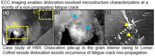
The dislocation pattern at the tip of a non-propagating fatigue crack in an Fe-25Cr-1N steel (mass%) was characterized by electron channeling contrast imaging. Planar dislocation arrays on two different slip planes were observed at the crack tip. Each planar dislocation array acts as a barrier to the motion of the other planar dislocations on different slip planes, contributing to the enhancement of the resistance to the crack propagation.
GRAPHICAL ABSTRACT
IMPACT STATEMENT
This paper employs ‘electron-channeling-contrast-imaging (ECCI) in scanning electron microscope’ technique to visualize fatigue crack tip dislocations in high nitrogen steel, and it showed highly planar dislocations interacting with pre-existing dislocations assisting non-propagating fatigue crack.
1. Introduction
The occurrence of the dislocation motion at a fatigue crack tip plays a crucial role on the crack growth. Specifically, the motion of a crack tip dislocation controls the work hardening in the vicinity of the crack tip [Citation1], formation of compressive residual stress at the crack wake [Citation2], and plastic deformation of the crack tip [Citation3]. For instance, the dislocation planarity strongly affects these factors, which can be utilized for improving the fatigue crack resistance. The dislocation planarity has been recognized to be controlled by a reduction in the stacking fault energy [Citation4,Citation5] and formation of a Cr–N atomistic interaction in austenitic steels [Citation6]. In particular, our previous study revealed that the dislocation planarity associated with the Cr–N interaction positively enhances the crack resistance [Citation7]. However, the nature of the effects of the crack tip dislocation on the crack resistance has not been clarified yet. This is due to the fact that the microstructure observation at a crack tip indeed requires crack length-specific, microstructurally local, stress-concentrated, and dislocation-resolved characterization techniques.
A strong candidate for this purpose is electron channeling contrast imaging (ECCI). ECCI enables the observation of large region [Citation8,Citation9], identical [Citation10,Citation11], and dislocation-resolved [Citation12–14] microstructures in a bulk specimen. In addition, the availability of the bulk specimen is expected to have a direct correlation with the replica method that has been used for fatigue crack growth observations. In this study, we describe the potential of ECCI for the inspection of crack tip dislocations in a high-nitrogen austenitic steel as a case study. Then, we discuss the nature of the effects of the crack tip dislocation on the fatigue crack resistance by combining the ECCI results with replica images.
2. Experimental procedure
Two steel compositions were used in this study, that is, Fe-25Cr-1N and Fe-18Cr-14Ni (mass%). The detailed chemical composition of each steel is listed in Table . Specimens of the Fe-25Cr-1N steel were prepared by solution nitriding, using Fe-25Cr mass% alloy with a single ferrite phase as base material. An ingot of the Fe-25Cr base material was produced by induction melting in vacuum, followed by homogenization at 1473 K, and hot-rolling to produce a 10-mm-thick plate. The specimens required for the fatigue and tensile tests were cut from the ingot and solution nitrided at 1473 K for 86.4 ks under a nitrogen atmosphere at 0.1 MPa, followed by water quenching to ensure that no austenite decomposition or nitride precipitation occurred upon cooling. As coarse-grained high nitrogen steels can exhibit brittle intergranular cracking, a grain refinement was carried out on the solution nitrided specimens in two stages [Citation15]. The specimens were first subjected to isothermal heat treatment at 1173 K for 0.42 ks, followed by re-austenitization at 1473 K for 0.3 ks, and subsequent water cooling. The tensile properties of the Fe-25Cr-1N steel have been reported to improve as a result of grain refinement [Citation15]. The Fe-18Cr-14Ni ingot was prepared by vacuum induction melting, forging, and groove rolling at 1273 K. The hot-rolled bar was then solution treated at 1273 K for 1 h, followed by water quenching to suppress the uncontrolled formation of second phases and segregation.
Table 1. Chemical compositions of the materials used in this study (mass%).
Rectangular dogbone-shaped tensile specimens of both steels with a 30-mm gauge length, 4-mm width, and 1-mm thickness were cut by electrical discharge machining (EDM), and tensile tests were conducted on three specimens at room temperature and at an initial strain rate of 10−3 s−1.
The fatigue test specimens, shown as an inset in Figure , were cut by EDM, and the damaged layer was subsequently removed by mechanical and electrochemical polishing. In this study, a special emphasis is placed on the resistance to the fatigue crack propagation rather than the crack initiation. Therefore, in order to observe the crack propagation behavior under threshold stress conditions, an artificial flaw was introduced at the center of the specimen, as shown in the inset in Figure . The artificial flaw was introduced using a combination of drilling and focused ion beam milling. Each fatigue test specimen was fixed on a round bar with the jig configured as reported in our previous paper [Citation16]. The fatigue tests were performed in a rotating bending fatigue test machine at room temperature, with a stress ratio of −1 and frequency of 30 Hz. The fatigue cracks were observed using an optical microscope with the aid of the replica technique.
The specimens after the fatigue test for ECCI were mechanically polished by colloidal silica long enough to remove the affected layers. ECCI was carried out in a Zeiss Smart SEM V06.00. The conditions used to observe the dislocation substructures from bulk samples are, accelerating voltage 30 kV, probe current of 10 nA, working distance of 3 mm, and a solid-state 4-quadrant BSE detector.
3. Results and discussion
The engineering stress–strain curves of the Fe-18Cr-14Ni and Fe-25Cr-1N steels are illustrated in Figure . The Fe-25Cr-1N steel showed a higher work hardening and tensile strength than the Fe-18Cr-14Ni steel. The 0.2% proof stress, tensile strength, and elongation are listed in Table . The increase in the yield strength of the Fe-25Cr-1N steel can be mainly attributed to the solid solution and the grain boundary hardening that occurs when the N is in the interstitial solid solution [Citation17,Citation18], as well as to the grain refinement of the Fe-25Cr-1N steel [Citation15]. Furthermore, a superior work hardening capability has been reported to stem from the dislocation planar glide associated with the Cr–N coupling [Citation19]. The dislocation planarity is also expected to enhance the resistance to the fatigue crack growth.
Figure 1. Engineering stress–strain curves of the Fe-18Cr-14Ni and Fe-25Cr-1N steels.
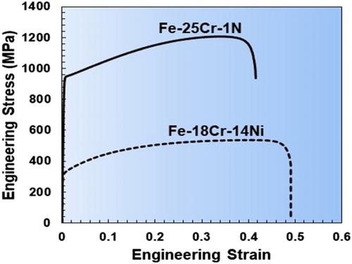
Table 2. 0.2% proof stress, tensile strength, and elongation of the Fe-25Cr-1N and Fe-18Cr-14Ni steels.
Here, we present the fatigue limits of two austenitic steels with and without nitrogen. In this study, the stress amplitude, which does not result in failure at 2 × 10⁷ cycles, is referred to as the fatigue limit. According to the rotating bending fatigue tests, the fatigue limits of the Fe-18Cr-14Ni and Fe-25Cr-1N steels were measured to be 100 and 275 MPa, respectively. Normally, the difference in fatigue limit could be explained by the tensile strength; the ratio between the fatigue limit and the tensile strength for the Fe-18Cr-14Ni and Fe-25Cr-1N steels was 0.19 and 0.23, respectively. These values indicate that the fatigue limit of the Fe-25Cr-1N steel is higher than that of the Fe-18Cr-14Ni steel. In fact, as demonstrated later, the high fatigue limit of the Fe-25Cr-1N steel originates from the occurrence of non-propagating fatigue cracks. Therefore, as similarly reported in a previous work [Citation7], the reason for the higher fatigue life associated with the crack propagation resistance is expected to arise from the enhancement of the dislocation planarity due to Cr–N solute interactions. As mentioned in the introduction, we attempted to provide microstructural image-based evidences for the contribution of the dislocation planarity to the crack resistance using ECCI coupled with the replica technique.
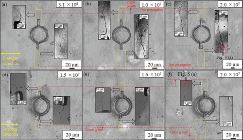
As mentioned above, the most important factor for understanding the improvement of the fatigue limit is the occurrence of non-propagating fatigue cracks (Figure ). Although the crack length in the Fe-18Cr-14Ni steel continuously increased until 2 × 10⁷ cycles, the Fe-25Cr-1N steel showed that a crack stopped to propagate after the crack initiation at the fatigue limit. Figure (a,c) demonstrate the non-propagating crack phenomenon in the Fe-25Cr-1N steel at 275 MPa. The crack propagated up to 1 × 10⁷ cycles (Figure (a,b)), after which the crack length was constant until 2 × 10⁷ cycles (Figure (b,c)). In contrast, the crack in the Fe-18Cr-14Ni steel at 100 MPa propagated on both sides of the hole with slip bands around the crack, and the crack length continuously increased, as shown in Figure (d–f). The reason for the crack length being constant in the Fe-25Cr-1N steel could be attributed to the nitrogen-enhanced dislocation planarity resulting in the dislocation pile-up at the crack tip. Therefore, the dislocation pattern at a tip of a non-propagating crack is a key for the enhancement of the fatigue limit.
Figure 2. Fatigue crack length plotted against number of cycles.
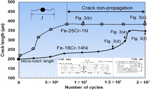
Figure 3. (a–c) Replica images of the Fe-25Cr-1N steel during the fatigue test at 275 MPa, (d–f) replica images of the Fe-18Cr-14Ni steel at 100 MPa. The red dashed lines indicate the positions of the crack tips. The insets are magnified images of the regions in correspondence of the crack tips.
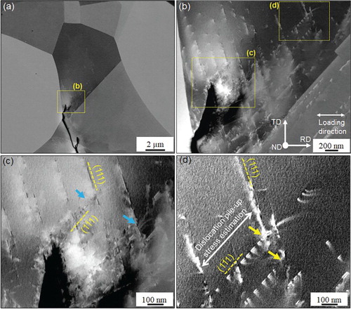
In order to examine the underlying mechanism of non-propagating fatigue cracks in the Fe-25Cr-1N steel, ECCI experiments were carried out to visualize the dislocations at the tip of the non-propagating fatigue crack. Figure shows the ECC images of the Fe-25Cr-1N steel at the crack tip corresponding to the crack tip shown in Figure (c). In the ECC images, when the surface crystallographic orientation is optimized for the Bragg’s condition, the backscattered electron intensity is minimized. Therefore, the orientation-optimized grain appears as a dark contrast, and the dislocation is imaged as a bright contrast owing to its elastic field [Citation14,Citation20]. In the set of images in Figure , the surface is inclined to show the surface orientation of the grain where the crack tip exists, reaching the Bragg’s condition. Figure (a) exhibits an overview of the ECC images showing the dislocation structure at the non-propagating fatigue crack tip. The ECCI successfully resolves the respective dislocations even near the crack tip, and clearly demonstrates highly planar dislocation arrays. It should be noted that the fatigue crack stops after passing across the grain boundary. In terms of dislocation planarity, the most important role would be played by the dislocation pile-up stress, which prevents the crack opening. In general, the evolution of the dislocation pile-up stress requires an obstacle against a leading dislocation on the planar array. A typical obstacle is the grain boundary. However, the grain boundary effect is minimized immediately after the crack passes across a grain boundary, since the distance between crack tip and grain boundary is maximized. Therefore, to evolve the dislocation pile-up stress, another microstructural obstacle is required. At the level of the microstructural obstacle, the activation of two slip systems was noted. Figure (c) shows a magnified image of a location from Figure (b). The dislocation motion is impinged at the dislocation plenary array existing on another slip plane, as indicated by the light blue arrows. In order to produce a clearer view of the interaction between the dislocations with different slip planes, images of dislocations that occur slightly far from the crack tip are shown in Figure (d). The spacing between the piling-up dislocations decreases upon reaching the intersection point of dislocations with different slip planes, which indicates that the dislocation pile-up stress acts on the piling-up dislocations because of the impingement of the planar dislocation motion. Here note that the dislocations shown in Figure (d) are extended significantly. Specifically, the dislocations along and (111) are dissociated as follows.
(1)
(2)
Figure 4. Electron channeling contrast (ECC) images of the Fe-25Cr-1N steel: (a) Dislocation structure at the crack tip corresponding to the crack tip outlined by the red dashed lines in Figure (c), (b), (c), and (d) magnified images of the regions outlined by the dashed lines in Figure (a) and (b). The blue and yellow arrows indicate the prevention of the dislocation motion at the intersections of two slip systems for each location shown in Figure (c and d). The normal and tensile direction (//RD) in the grain surrounding the crack tip are and
respectively.
The leading partials in Equations (1) and (2) react with each other:
(3)
The a/6
dislocation lying on (010) is immobile, namely, Lomer–Cottrell reaction occurs. The Lomer–Cottrell sessile dislocation prevents further motion of dislocations. In high-nitrogen austenitic steels, the formation of Lomer–Cottrell sessile dislocations has been recognized to be a major mechanism of work hardening [Citation19,Citation21]. Hence, the nitrogen in austenitic steels plays a dual role in assisting the crack closure. First, the nitrogen enhances the dislocation planarity, which induces a high pile-up stress on each crack tip dislocation. The pile-up stress can be estimated by the following equation:
(4)
where G is shear modulus, b is Burgers vector,
is Poisson’s ratio, X is the distance between dislocations, and n is the number of dislocations. Based on the dislocation spacing marked by the white arrow in Figure (d), number of dislocations are counted to be 10; therefore, the pile-up stress was estimated to be 50 MPa. The pile-up stress is significant compared with the remote stress, and it increases the shear stress required for a new dislocation emission from the crack tip. Second, an interaction between the planar dislocation arrays on the two different slip planes causes formation of Lomer–Cottrell sessile dislocations. The formation of Lomer–Cottrell sessile dislocations enables the pile-up stress evolution even when the crack tip position is far from the grain boundaries. As a result, the nitrogen enhances the resistance to the crack propagation and associated fatigue limit.
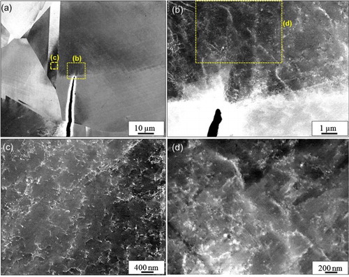
In addition, ECCI was performed to visualize the dislocations at the crack tip of the Fe-18Cr-14Ni steel. Figure shows the ECC images of the Fe-18Cr-14Ni steel at the crack tip corresponding to the crack tip shown in Figure (f). Figure (c) shows that the dislocations at the crack tip tangled each other and cellular type of dislocations was formed. In contrast, the Fe-25Cr-1N steel showed planar dislocations at the crack tip (Figure (a)), due to nitrogen-enhanced dislocation planarity. Therefore, the Fe-25Cr-1N steel showed a higher fatigue limit and non-propagating fatigue crack phenomena.
Figure 5. Electron channeling contrast (ECC) images of the Fe-18Cr-14Ni steel: (a) Dislocation structure at the crack tip corresponding to the crack tip outlined by the red dashed lines in Figure (f), (b and c) magnified images of the regions outlined by the dashed lines in Figure (a) and (b).
4. Conclusions
In this study, dislocation arrays specifically occurring at a tip of a non-propagating fatigue crack in a high-nitrogen austenitic steel could be observed by using ECCI coupled with the replica technique. The dislocations at the crack tip are highly planar, and its motion is strongly impinged by the planar dislocation arrays on another slip plane. The dislocation pile-up stress associated with the high planarity and impingement might assist the non-propagation of the fatigue crack, which is one of the crucial reasons for enhancing the fatigue limit of high nitrogen steels.
Disclosure statement
No potential conflict of interest was reported by the authors.
ORCID
Motomichi Koyama http://orcid.org/0000-0002-5006-9976
Additional information
Funding
References
- Ohr S. An electron microscope study of crack tip deformation and its impact on the dislocation theory of fracture. Mater Sci Eng. 1985;72(1):1–35.
- Cleveringa HHM, Van Der Giessen E, Needleman A. A discrete dislocation analysis of residual stresses in a composite material [Article]. Philos Mag A. 1999;79(4):893–920.
- Rice J. Mechanics of crack tip deformation and extension by fatigue. Fatigue crack propagation. Philadelphia: ASTM International; 1967.
- Kruml T, Pola J, Obrtli K, et al. Dislocation structures in the bands of localised cyclic plastic strain in austenitic 316L and austenitic-ferritic duplex stainless steels. Acta Mater. 1997;45(12):5145–5151.
- Gerold V, Karnthaler H. On the origin of planar slip in fcc alloys. Acta Metall. 1989;37(8):2177–2183.
- Oda K, Kondo N, Shibata K. X-ray absorption fine structure analysis of interstitial (C, N)-substitutional (Cr) complexes in austenitic stainless steels. ISIJ Int. 1990;30(8):625–631.
- Habib K, Koyama M, Tsuchiyama T, et al. Fatigue crack non-propagation assisted by nitrogen-enhanced dislocation planarity in austenitic stainless steels. Int J Fatigue. 2017;104:158–170.
- Ahmed J, Wilkinson A, Roberts S. Characterizing dislocation structures in bulk fatigued copper single crystals using electron channelling contrast imaging (ECCI). Philos Mag Lett. 1997;76(4):237–246.
- Koyama M, Tasan CC, Akiyama E, et al. Hydrogen-assisted decohesion and localized plasticity in dual-phase steel. Acta Mater. 2014;70:174–187.
- Ahmed J, Roberts SG, Wilkinson A. Characterizing dislocation structure evolution during cyclic deformation using electron channelling contrast imaging. Philos Mag. 2006;86(29–31):4965–4981.
- Koyama M, Springer H, Merzlikin SV, et al. Hydrogen embrittlement associated with strain localization in a precipitation-hardened Fe–Mn–Al–C light weight austenitic steel. Int J Hydrogen Energy. 2014;39(9):4634–4646.
- Ng B, Simkin B, Crimp M. Application of the electron channeling contrast imaging technique to the study of dislocations associated with cracks in bulk specimens. Ultramicroscopy. 1998;75(3):137–145.
- Gutierrez-Urrutia I, Raabe D. Dislocation density measurement by electron channeling contrast imaging in a scanning electron microscope. Scr Mater. 2012;66(6):343–346.
- Zaefferer S, Elhami N-N. Theory and application of electron channelling contrast imaging under controlled diffraction conditions. Acta Mater. 2014;75:20–50.
- Onomoto T, Terazawa Y, Tsuchiyama T, et al. Effect of grain refinement on tensile properties in Fe-25Cr-1N alloy. ISIJ Int. 2009;49(8):1246–1252.
- Habib K, Koyama M, Noguchi H. Impact of Mn–C couples on fatigue crack growth in austenitic steels: Is the attractive atomic interaction negative or positive? Int J Fatigue. 2017;99(Part 1):1–12.
- Simmons J. Overview: high-nitrogen alloying of stainless steels. Mater Sci Eng A. 1996;207(2):159–169.
- Reed RP. Nitrogen in austenitic stainless steels. JOM. 1989;41(3):16–21.
- Ojima M, Adachi Y, Tomota Y, et al. Work hardening mechanism in high nitrogen austenitic steel studied by in situ neutron diffraction and in situ electron backscattering diffraction. Mater Sci Eng A. 2009;527(1):16–24.
- Gutierrez-Urrutia I, Zaefferer S, Raabe D. Electron channeling contrast imaging of twins and dislocations in twinning-induced plasticity steels under controlled diffraction conditions in a scanning electron microscope. Scr Mater. 2009;61(7):737–740.
- Kubota S, Xia Y, Tomota Y. Work-hardening behavior and evolution of dislocation-microstructures in high-nitrogen bearing austenitic steels. ISIJ Int. 1998;38(5):474–481.