
ABSTRACT
We significantly improved the fatigue properties of an electron beam melting (EBM)-fabricated biomedical Co–Cr–Mo alloy by a simple post-production heat treatment without any deformation process. The fatigue properties were improved by transforming the as-EBM-fabricated dual-phase structure (containing both the ϵ-hcp and γ-fcc phases) into the dominant ϵ-hcp phase structure, and they were further improved significantly by reverse transforming it into the dominant grain-refined γ-fcc phase structure at certain ageing conditions. It provides an accessible avenue for improving the mechanical properties of additive-manufactured metallic components.
GRAPHICAL ABSTRACT
IMPACT STATEMENT
The fatigue properties of additive-manufactured biomedical Co–Cr–Mo alloy were significantly improved though manipulating the fatigue behaviors, which was achieved by an accessible post-production heat treatment.
1. Introduction
Biomedical Co–Cr–Mo (CCM) alloys are widely used as orthopedic implants in knee joints and artificial hip because of their high biocompatibility, good mechanical properties, and superior wear and fatigue resistance [Citation1–3]. The alloys generally contain two kinds of crystal structures: the γ-fcc phase (stable at high temperatures typically exceeding 900°C) and the ϵ-hcp phase (stable at room temperature); the relative fractions of the γ and ϵ phases as well as their grain sizes significantly affect the mechanical properties of these alloys [Citation4]. Nevertheless, their limited ductility and high hardness values hinder the fabrication of complex-shaped prostheses by casting, plastic deformation, and machining. These predicaments are expected to be overcome by the electron beam melting (EBM) fabrication process, which is an additive manufacturing technique based on incremental layer-by-layer manufacturing. The process uses metal powders or wires as feedstock, which are selectively melted by a focused electron beam and subsequently consolidated to form parts of a component [Citation5–7]. Near-net-shaped metallic components containing fewer defects and cracks can be fabricated using EBM [Citation8–10]. Because of these benefits, several researchers have focused on fabricating the components of CCM alloys by the EBM method [Citation11–14].
The orthopedic implants of CCM alloys that function as bones to replace failed hard tissues usually serve under cyclic loadings in the living body environment. The reliability of these implants after implantation is largely determined by their strength and fracture toughness. Fatigue fracture has been identified as a major problem that causes implant loosening and ultimate failure [Citation15,Citation16]. The artificial joints made of CCM alloys are increasingly used in younger and more active patients nowadays, where the service duration is much longer under more rigorous service environment. Therefore, the evaluation and improvement of mechanical properties of the alloys become more important for their confident use as long-term implants. To date, much effort has been devoted to optimizing the mechanical properties of CCM alloys by thermomechanical treatments. Nevertheless, these techniques are not suitable for EBM-fabricated components because plastic deformation cannot be imposed during near-net-shape production. Previous studies indicated that grain refinement can be achieved by two-stage heat treatment in the alloys [Citation17,Citation18]. In the present study, we attempted to improve the fatigue properties of EBM-fabricated biomedical CCM alloys by the simple and accessible post-production heat treatment.
2. Experiment
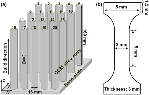
Gas-atomized powders with a nominal composition of Co–28Cr–6Mo–0.23C–0.2N (wt%) were used to build rods by Arcam A2 EBM system. The size of powders is ranging from 45 to 150 µm, and the average diameter is 64 µm. Cylindrical rods of 16 mm diameter and 160 mm length were vertically built on a stainless steel base plate with the built direction (BD) parallel to the cylindrical axis, i.e. perpendicular to the base plate as shown in (a). The fabrication process was conducted at preheating temperature (850°C), electron beam acceleration voltage (60 kV), beam current (6–15 mA), beam scanning speed (400–900 mm/s), focus offset (−70-0 µm), line offset (200–250 µm), and layer thickness (70 µm). During the hatching, the scan direction of the electron beam was controlled by using a mode that randomly selected scanning along the x-axis or y-axis on every layer. Furthermore, the power and scanning speed of the electron beam were controlled automatically by the operating program of the EBM machine [Citation13]. Dog-bone-shaped specimens were sliced from the middle part of one rod (80 mm from the base plate), keeping their longitudinal direction parallel to the BD of the rod. The specimens used for the fatigue tests had a gauge section of 5.0 mm length, 3.0 mm thickness, and 2.0 mm width ((b)).
Figure 1. Schematic drawing of (a) cylindrical rods fabricated by the EBM process and (b) dog-bone-shaped specimen for fatigue tests.
The specimens were divided into three groups: the first group without treatment; the second group aged at 750°C for 12 h, hereinafter denoted by HT specimens, where the initial phases transformed to the ϵ-hcp phase; and the third group aged at 750°C for 12 h, water quenched, and subsequently aged at 1000°C for 10 min, denoted by RT specimens, where the ϵ-hcp phases reverse transformed to the γ-fcc phase. The ageing temperatures were determined based on the TTT curves and the previous study [Citation12,Citation17]. All the HT and RT specimens were water quenched to room temperature after ageing. The specimens were ground and then mirror-finished with colloidal silica. The microstructures of the specimens were characterized by electron backscatter diffraction (EBSD) using a field-emission scanning electron microscope (FE-SEM) with an accelerating voltage of 15 kV. Fatigue tests (both stress-controlled and strain-controlled) were conducted by uniaxial fully reversed tensile and compression until fracture. The stress-controlled fatigue test was performed under a constant stress amplitude of 600 MPa for a period of 20 s, with the mean stress per cycle being zero. In the strain-controlled fatigue test, the specimens were subjected to a constant plastic strain amplitude of 1% with the strain rate of 4.0 × 10⁻³ s−1 until ultimate failure, with the mean strain per cycle being zero. Both the fractured surface and side surface were observed by FE-SEM. Cross-sectional microstructures near the side surface of the samples were observed by scanning transmission electron microscopy (STEM) using thin-foil specimens prepared by a combined SEM/focused ion beam (FIB) system.
3. Results and discussion
(a–f) illustrates the EBSD maps depicting the microstructures of the as-built ((a,b)), HT ((c,d)), and RT ((e,f)) specimens prior to fatigue tests. (g) shows the average grain size and fcc phase fraction of the specimens. The phase map in (a) demonstrates that the as-built specimen consists of a γ-fcc and ϵ-hcp dual phases, with the γ phase containing a higher fraction of low angle grain boundaries (LAGBs) than the ϵ phase. The corresponding inverse pole preferentially orientated with the or
ϵ axis parallel to the building direction, respectively. After ageing the specimen at 750°C for 12 h (HT specimen), both the γ phase fraction and LAGBs proportion decreased significantly ((c)), indicating that the initial γ phase transformed into the ϵ phase. Moreover, the ϵ phase in HT specimen exhibits an intensified texture of
ϵ ((d)) compared with the as-built specimen. When the specimen was additionally aged at 1000°C for 10 min (RT specimen), the ϵ phase almost entirely transformed into the γ phase with refined grains ((e)). In addition, a
texture as well as a newly formed
texture were observed ((f)).
Figure 2. (a–f) EBSD phase maps and inverse pole figure (IPF) maps of as-EBM built (a and b), heat-treated (c and d) and reverse-transformed (e and f) specimens of biomedical Co–Cr–Mo alloy prior to fatigue tests. (g) The corresponding average grain sizes and fcc phase fractions.
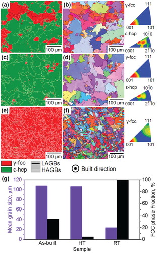
The grains of the as-built and HT specimens were relatively coarse with mean diameters of 108 and 106 µm, respectively, while the grains of the RT specimen were refined to a mean diameter of 24 µm. In contrast, the γ phase fraction reduced significantly from 34.7% (as-built) to 4.3% (HT) and then increased to 99.8% (RT). In this alloy, γ → ϵ or ϵ → γ phase transformations can be induced isothermally by ageing the specimens at stable ϵ or γ phase temperatures. The γ → ϵ transformation by ageing (750°C for 12 h in the present study) was achieved by a complex two-stage process, which proceeded concurrently with discontinuous precipitation of carbide particles [Citation19]. The nucleation of martensitic embryos shows a crystallographic orientation relationship, which can be described as {0001}hcp//{111}fcc, [Citation19,Citation20]. Therefore, a strong texture was observed in the HT sample. On the other hand, the grains of the RT specimen were significantly refined through ϵ → γ transformation by ageing at 1000°C for 10 min. This was achieved by reverse transformation from a lamellar or pearlitic-type phase to the fcc phase [Citation17,Citation18], which is analogous to the grain refinement achieved by reverse transforming a lamellar structure to austenite in carbon or high nitrogen steel [Citation21].
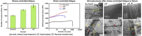
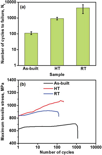
(a) shows the number of cycles to failure (Nf) in stress-controlled fatigue. The Nf value increased from 113 cycles (as-built) to 933 cycles (HT), and eventually significantly increased to 4462 cycles (RT). Both the above-mentioned ageing regime (γ → ϵ and ϵ → γ) can significantly increase the stress-controlled fatigue life. (b) shows the maximum tensile stress during the strain-controlled fatigue until failure. Both HT and RT specimens exhibit a much higher yield strength than the as-built specimen. The strengthening of the HT specimen is mainly due to the increase in its ϵ phase fraction, which enhances the strength but decreases the ductility of the alloy [Citation4,Citation22], whereas the strengthening of the RT specimen is mainly attributed to its grain refinement. In contrast with the as-built, the HT specimens exhibit strong strain hardening with an increase in cycles, whereas the as-built specimen does not show obvious hardening during the entire strain-controlled fatigue test. This is possibly because a relatively large amount of thermal residual stress was accumulated in the as-built specimen due to the rapid fusion and consolidation of powders in the EBM process, and the residual stress relaxation during fatigue (softening) traded hardening off. However, the HT and RT specimens contain much less residual stress because of stress relaxation during ageing. Therefore, the dislocation nucleation and multiplication in these specimens lead to an obvious hardening phenomenon. Moreover, the HT specimen shows the strongest hardening effect, which is probably due to the lack of slip systems in the ϵ-hcp phase.
Figure 3. (a) Number of cycles to failure of stress-controlled fatigue tests and (b) maximum tensile stress of strain-controlled fatigue tests of as-EBM built, heat treated and reverse-transformed CCM alloys.
shows the morphologies of the fractured surface ((a–c)) and side surface ((d–i)) of the specimens after stress-controlled fatigue to failure. All the as-built ((a)), HT ((b)), and RT ((c)) specimens show a dimpled fracture surface, and many particles (precipitates) were observed within the dimples. The fractured surfaces of the as-built and RT specimens are relatively ‘flat’ while that of the HT sample is relatively ‘rough’ with plenty of cleavage-like facets. This indicates that the fatigue fracture of the as-built and RT specimens is dimple-fracture, but that of the HT specimen is a hybrid of dimple-fracture and cleavage fracture. Generally, fatigue proceeds in three main stages: cracks initiated at stress concentration propagate along the load axis in Stage I, cracks grow and propagate perpendicular to the load axis in Stage II, and eventually, fracture occurs in Stage III. The large amount of precipitates within the dimples suggest that voids were generated in the precipitates, which then grew and coalesced into cracks in the CCM alloy. Micro-cracks shown in (d–i) were formed at the precipitates and propagated along the load axis, indicating that they are the cracks of Stage II.
Figure 4. SEM images showing fracture surface (a–c) and side surface (d–f) of as-EBM built (a and d), heat-treated (b and e) and reverse-transformed (c and f) samples after stress-controlled fatigue to failure; (g–i) magnified view of (d–f). The view direction is either parallel (a–c) or perpendicular (d–i) to the stress-loading axis in fatigue tests.
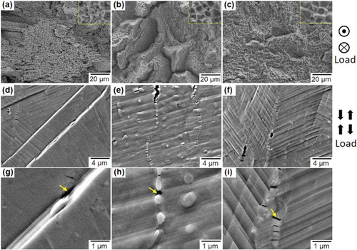
Besides the cracks, both fine and coarse slip traces (STs), i.e. extrusions and intrusions, were formed in the as-built sample as shown in (d) and its magnified view in (g). Moreover, micro-cracks can be observed within the coarse slip traces indicated by the arrowhead, which are formed as a result of stress concentration at the surface discontinuity introduced by the extrusions and intrusions. On the other hand, very fine STs as well as cracks are observed in the HT specimen, wherein the cracks propagate along the stress-loading axis, which is nearly perpendicular to the STs, as shown in (e) and the magnified (h). Due to the lack of slip systems in the ϵ-hcp phase, it is difficult to accommodate the macro plastic deformations through the cooperation of the different slip systems in the HT specimen. Therefore, stress concentration at crack tips can rarely be relaxed by cross-slips during propagation. As a result, cracks propagate through the entire grain, leading to cleavage fracture of the grains with an orientation that is hard to be plastic deformed along the stress-loading axis. In the RT specimen, cracks mainly form and propagate along the precipitates at the grain boundaries ((f) and magnified (i)). All the evidence in the present study indicates that the cracks are initiated either at precipitates or at the surface discontinuity introduced by the extrusions and intrusions.
displays the STEM images showing the microstructures of the as-built ((a,d)), HT ((b,e)), and RT ((c,f)) specimens after stress-controlled fatigue to failure. The incident beam was set parallel to {111}γ//(0001)ϵ. The black arrowheads indicate the steps on the surface while the red arrowheads indicate the dislocations in the ϵ-phase, and the yellow arrowheads indicate the ϵ-laths formed in the γ-matrix, respectively. A stepwise surface relief, a wide ϵ-band, and several narrow ϵ-laths were observed in the as-built specimen. The vertical height of the step is approximately 400 nm ((a)), and the width of the ϵ-band is approximately 100 nm ((d)). The ϵ-band, which acts as a connector between the extrusions and intrusions, was formed along {111}γ by γ → ϵ strain-induced martensite transformation (SIMT) during fatigue. It contains a much higher density of dislocations than the γ matrix, which is mainly dislocations. It can be deduced that the intrusions and extrusions on the surface were formed mainly by plastic deformation inside the ϵ martensite plates, which is in agreement with a previous finding [Citation23,Citation24]. Stress accumulates preferentially at the connectors of the extrusions and intrusions after their formation, which leads to crack initiation with an increase in fatigue cycle. This is a possible reason for the low fatigue duration of the as-built specimen. However, a single ϵ-phase without stepwise surface relief and band structure was observed in the HT specimen ((b)), wherein the ϵ-matrix contained high density of dislocations ((e)). This indicates that the fatigue proceeded mainly by plastic deformation of the ϵ-matrix in the HT specimen without SIMT.
Figure 5. STEM images showing microstructures of as-EBM built (a and d), heat-treated (b and e) and reverse-transformed (c and f) samples after stress-controlled fatigue to failure; (d–f) magnified view of (a–c). The incident beam is parallel to {111}γ//(0001)ϵ.
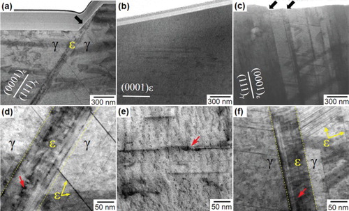
The fatigue behavior of the ϵ-phase significantly differs from that of the γ-phase mainly due to the difference in the lattice structure and stacking fault energy (SFE). Deformation twinning or γ → ϵ martensitic transformation occurs easily in the γ-fcc matrix at room temperature due to its negative SFE. In contrast, neither twinning nor martensite forms in the ϵ-hcp phase due to its high SFE value at room temperature [Citation25,Citation26]. Therefore, the HT specimen exhibits longer fatigue duration, but lack ductility as compared to the as-built specimen. In the case of the RT sample, a relatively flat stepwise surface relief resulting from a large number of extrusions and intrusions can be observed from (c). The specimen has a larger amount of ϵ-bands and ϵ-laths than the as-built specimen, which appears as dark contrasts in (c,f). A 70-nm-wide ϵ-band, besides many narrow ϵ-laths, is observed in the magnified image in (f). The ϵ-band contains a high density of dislocations, similar to the as-built specimen. Therefore, the extrusions and intrusions were also formed by plastic deformation within the ϵ martensites. The large number of ϵ martensites formed on {111}γ can collectively accommodate the plastic strain of the γ matrix, which reduces stress accumulation; thus, the fatigue properties of the RT specimen were significantly improved.
The γ → ϵ martensitic transformation is attributed to the motion of Shockley partial dislocations on the alternative {111} planes of the γ phase. A previous study [Citation23] reported that perfect dislocations of are preferentially activated in the coarse-grained γ-matrix, with fewer ϵ martensites formed after deformation. However, Shockley partial dislocations of
are preferentially activated in the fine-grained γ-phase. Therefore, larger amounts of ϵ martensites were formed in the RT specimen with fine γ grains than in the as-built specimen with coarse γ grains, which contributed to the improvement in fatigue property.
4. Conclusion
In the present study, we significantly improved the fatigue properties of an EBM-built biomedical CCM alloy by a simple post-production heat treatment. Both the duration in stress-controlled fatigue and the strength in strain-controlled fatigue were increased by transforming the initial as-EBM-built γ + ϵ dual phase to the dominant ϵ phase, and were further significantly improved by reverse transforming the ϵ phase to the γ phase with refined grains. The improvement was achieved by manipulating the fatigue deformation behaviors and refining the grain structures, which provides a novel avenue for improving the mechanical properties of additive-manufactured metallic components.
Disclosure statement
No potential conflict of interest was reported by the authors.
Additional information
Funding
References
- Rose RM. Materials for internal prostheses, yearbook of science and technology. New York (NY): McGraw-Hill Book Co.; 1974.
- Devine TM, Wulff J. Cast vs. wrought cobalt-chromium surgical implant alloys. J Biomed Mater Res. 1975;9:151–167. doi: 10.1002/jbm.820090205
- Niinomi M. Recent metallic materials for biomedical applications. Metall Mater Trans A. 2002;33:477–486. doi: 10.1007/s11661-002-0109-2
- Mani A, Salinas-Rodrigez A, Lopez HF. Deformation induced FCC to HCP transformation in a Co–27Cr–5Mo– 0.05C alloy. Mater Sci Eng A. 2011;528:3037–3043. doi: 10.1016/j.msea.2010.12.024
- Carroll BE, Palmer TA, Besse AM. Anisotropic tensile behavior of Ti–6Al–4V components fabricated with directed energy deposition additive manufacturing. Acta Mater. 2015;87:309–320. doi: 10.1016/j.actamat.2014.12.054
- Brandl E, Palm F, Michailov V, et al. Mechanical properties of additive manufactured titanium (Ti–6Al–4V) blocks deposited by a solid-state laser and wire. Mater Des. 2011;32:4665–4675. doi: 10.1016/j.matdes.2011.06.062
- Herzog D, Seyda V, Wycisk E, et al. Additive manufacturing of metals. Acta Mater. 2016;117:371–392. doi: 10.1016/j.actamat.2016.07.019
- Murr LE, Gaytan SM, Medina F, et al. Characterization of Ti–6Al–4V open cellular foams fabricated by additive manufacturing using electron beam melting. Mater Sci Eng A. 2010;527:1861–1868. doi: 10.1016/j.msea.2009.11.015
- Ramirez DA, Murr LE, Li SJ, et al. Open-cellular copper structures fabricated by additive manufacturing using electron beam melting. Mater Sci Eng A. 2011;528:5379–5386. doi: 10.1016/j.msea.2011.03.053
- Murr LE, Gaytan SM, Ceylan A, et al. Characterization of titanium aluminide alloy components fabricated by additive manufacturing using electron beam melting. Acta Mater. 2010;58:1887–1894. doi: 10.1016/j.actamat.2009.11.032
- Sun SH, Koizumi Y, Kurosu S, et al. Build direction dependence of microstructure and high-temperature tensile property of Co–Cr–Mo alloy fabricated by electron beam melting. Acta Mater. 2014;64:154–168. doi: 10.1016/j.actamat.2013.10.017
- Sun SH, Koizumi Y, Kurosu S, et al. Phase and grain size inhomogeneity and their influences on creep behavior of Co–Cr–Mo alloy additive manufactured by electron beam melting. Acta Mater. 2015;86:305–318. doi: 10.1016/j.actamat.2014.11.012
- Takashima T, Koizumi Y, Li Y, et al. Effect of building position on phase distribution in Co–Cr–Mo alloy additive manufactured by electron-beam-melting. Mater Trans. 2016;57:2041–2047. doi: 10.2320/matertrans.Y-M2016826
- Koizumi Y, Okazaki A, Chiba A, et al. Cellular lattices of biomedical Co–Cr–Mo alloy fabricated by electron beam melting with the aid of shape optimization. Addit Manuf. 2016;12:305–313. doi: 10.1016/j.addma.2016.06.001
- Niinomi N. Fatigue characteristics of metallic biomaterials. Int J Fatigue. 2007;29:992–1000. doi: 10.1016/j.ijfatigue.2006.09.021
- Teoh SH. Fatigue of biomaterials: a review. Int J Fatigue. 2000;22:825–837. doi: 10.1016/S0142-1123(00)00052-9
- Kurosu S, Matsumoto H, Chiba A. Grain refinement of biomedical Co–27Cr–5Mo–0.16N alloy by reverse transformation. Mater Lett. 2010;64:49–52. doi: 10.1016/j.matlet.2009.10.001
- Zangeneh Sh. Ketabchi M. Grain refinement by pearlitic-type constituents in Co–28Cr–5Mo–0.3C alloy. Mater Lett. 2013;94:206–209. doi: 10.1016/j.matlet.2012.11.074
- Rajan K. Phase transformations in a wrought Co–Cr–Mo-C alloy. Metall Trans A. 1982;13:1161–1166. doi: 10.1007/BF02645497
- Nishiyama Z. Martensitic transformations. London: Academic Press; 1978. p. 467.
- Nakada N, Hirokawa N, Tsuchiyama T, et al. Grain refinement of nickel-free high nitrogen austenitic stainless steel by reversion of eutectoid structure. Scripta Mater. 2007;57:153–156. doi: 10.1016/j.scriptamat.2007.03.022
- Saldivar Garcia ADJ, Mani Medrano A, Salinas Rodriguez A. Formation of HCP martensite during the isothermal aging of an FCC Co–27Cr–5Mo–0.05C orthopedic implant alloy. Metall Mater Trans A. 1999;30:1177– 1184. doi: 10.1007/s11661-999-0267-6
- Mitsunobu T, Koizumi Y, Lee BS, et al. Role of strain-induced martensitic transformation on extrusion and intrusion formation during fatigue deformation of biomedical Co–Cr–Mo-N alloys. Acta Mater. 2014;81:377–385. doi: 10.1016/j.actamat.2014.08.039
- Mitsunobu T, Koizumi Y, Lee BS, et al. Asymmetric slip trace formation in tension/compression cyclic deformation of biomedical Co–Cr–Mo–N alloy with negative stacking fault energy. Scripta Mater. 2014;74:52–55. doi: 10.1016/j.scriptamat.2013.10.015
- Matsumoto H, Kurosu S, Lee BS, et al. Deformation mode in biomedical Co–27% Cr–5% Mo alloy consisting of a single hexagonal close-packed structure. Scripta Mater. 2010;63:1092–1095. doi: 10.1016/j.scriptamat.2010.08.006
- Matsumoto H, Koizumi Y, Ohashi T, et al. Microscopic mechanism of plastic deformation in a polycrystalline Co–Cr–Mo alloy with a single hcp phase. Acta Mater. 2014;64:1–11. doi: 10.1016/j.actamat.2013.11.005