
ABSTRACT
An FeCoCrNi high-entropy alloy (HEA) was deformed at ambient temperature and cryogenic temperatures down to 4.2 K. Phase transformation from a face-centered cubic (FCC) structure to a hexagonal close-packed (HCP) structure occurred during cryogenic deformation. Lowering the temperature promotes the transformation. Atomic-scale structural characterisation suggested that the formation of the HCP structure was achieved via the glide of Shockley partial dislocations on every other plane. Due to the kinetic limitation, the occurrence of this transformation was limited even though theoretical investigations predicted lower free energy of the HCP phase than that of the FCC phase in the HEA.
GRAPHICAL ABSTRACT
IMPACT STATEMENT
Atomic-scale FCC–to–HCP transformation was revealed in an FeCoCrNi high-entropy alloy during cryogenic-temperature deformation. The transformation was restricted due to the kinetic limitation.
1. Introduction
High-entropy alloys (HEAs), referred to entropy-stabilized solid solution alloys with multi-principal elements having approximately equiatomic concentrations, have triggered substantial research interest in the last decade [Citation1–4]. Due to the tremendous compositional variability of HEAs, their configuration entropy can be sophisticatedly engineered to stabilise a single solid solution state [Citation1–4]. Therefore, HEAs usually exhibit a single-phase structure with high symmetry including face-centered cubic (FCC) [Citation5–7], body-centered cubic (BCC) [Citation8–10] and hexagonal close-packed (HCP) structures [Citation11–13]. The heavy lattice distortion and the sluggish diffusion induced by mixing multiple elements enable HEAs to possess exceptionally high structural stability and excellent mechanical properties [Citation1–4]. For example, the FeCoCrNiMn HEA maintains its single FCC structure over a large temperature range from cryogenic temperatures up to the melting temperature without phase transformation [Citation5]. In addition, exceptional combination of mechanical properties under various temperatures was achieved in this alloy, including outstanding cryogenic fracture toughness due to the occurrence of deformation nanotwinning [Citation5,Citation6,Citation14,Citation15].
It was generally proposed that maximised configurational entropy could be the main reason for the single-phase stability of HEAs [Citation1–4]. However, this type of entropy is only one of the factors contributing to the Gibbs free energy that plays the crucial role in the phase formation and phase stability. By recourse to a finite-temperature ab initio method, the significance of the formation enthalpy and other entropy contributers in the formation of these single-phase solid solutions has been essentially identified [Citation16]. Therefore, the originally strict HEA rule regarding single-phase stability can be thermodynamically relaxed. This increasingly catalyzes the novel HEA design strategy to introduce twinning-induced plasticity (TWIP) [Citation17] and transformation-induced plasticity (TRIP) effects [Citation18–20] into HEAs through the optimisation of their stacking fault energy (SFE) via tuning their chemical compositions and concentrations. For example, a Fe40Mn40Co10Cr10 HEA was developed that expands the nanotwinning deformation behaviour from cryogenic temperatures to ambient temperature [Citation17], while Fe50Mn30Co10Cr10 with a dual-phase (FCC and HCP) structure demonstrates TRIP-assisted excellent strength–ductility combination [Citation18].
Apart from the compositional complexity of HEAs, their high structural stability was apparently challenged when various extreme processing and deformation conditions were imposed. The decomposition of FeCoCrNiMn HEA occurred after long-term annealing at intermediate temperatures [Citation21,Citation22]. The polymorphic transition from FCC to HCP in this HEA was detected during compression at high pressure but the atomic mechanism of the transformation remains unknown [Citation23,Citation24]. In addition, finite temperature ab initio simulations proposed that the HCP structure in FeCoCrNiMn HEA may have the lowest free energy at room temperature, compared with its FCC and BCC counterparts [Citation16]. The ab initio calculations also predicted the occurrence of the HCP phase at cryogenic conditions by estimating the temperature dependent SFE of this HEA [Citation25]. However, the predicted HCP phase in HEAs is still seldom observed at ambient pressure and cryogenic temperatures. In this letter, we report cryogenic-deformation-induced phase transformation from FCC to HCP in an FeCoCrNi HEA and reveal the atomic-scale mechanism of the transformation. This polymorphic phase transformation is significant scientifically, for the comprehensive understanding of the deformation behaviour and phase stability of HEAs, and technologically, for guiding the design of HEAs with advanced mechanical properties [Citation26].
2. Experimental details
The equiatomic FeCoCrNi alloy was produced by vacuum induction levitation melting of the constituent elements with at least 99.9 wt% purity in high-purity argon atmosphere. The ingot was melted at least three times to improve the chemical homogeneity and then annealed at 1373 K for 20 h, followed by hot-forged at 1473 K for six times [Citation27]. The as prepared FeCoCrNi HEA is a single-phase FCC solid solution with an average grain size of ∼13 µm and compositional homogeneity [Citation27]. Tensile tests were carried out using specimens with gauge dimensions of 15 mm × 3 mm × 1.7 mm at a strain rate of 10−3 s−1 and 293 K (the ambient temperature), 77 K (the liquid nitrogen temperature) and 4.2 K (the liquid helium temperature) in a MTS-SANS CMT5000 universal testing machine. All the samples were deformed to fracture. Uniform tensile strain of ∼0.63, ∼0.78 and ∼0.62 at the three temperatures, respectively, was achieved immediately before necking and fracture [Citation27]. Plan-view specimens for transmission electron microscopy (TEM) characterisation were taken from the uniformly deformed regions (i.e. away from the necking areas). The TEM specimens were mechanically ground to a thickness of ∼100 µm, and then thinned by a twin-jet method using a Struers TenuPol-5 jet electropolishing unit and a solution of 6 vol. % perchloric acid in methanol under an operating voltage of 20 V at −30°C. TEM, high resolution TEM (HRTEM) and high-angle annular dark-field (HAADF) scanning TEM (STEM) observations were conducted to characterise post-deformation microstructures using a JEOL 3000F TEM operating at 300 kV and a JEOL ARM200F aberration-corrected TEM operating at 200 kV.
3. Results and discussion
Typical microstructures of the HEA after tensile deformation at 293 K, 77 K and 4.2 K, were exhibited in Figure (a–c), respectively, while the corresponding selected area electron diffraction (SAED) patterns were shown in Figure (d–e). It is clear that the plastic deformation at ambient temperature was dominated by dislocation activities, as shown in the TEM image of Figure (a) and the SAED pattern of Figure (d), although a small amount of deformation twins also formed [Citation28]. Similar to that in an FeCoCrNiMn HEA [Citation5,Citation28], the dislocation structure, which was planar at low strains, has reorganised into loose dislocation cells at large strains, as marked by arrows in Figure (a). When the HEA was deformed at 77 K and 4.2 K, the prominent microstructure morphologies were mainly sculptured by extensive deformation twinning activities, as illustrated in Figure (b,c) respectively. The correpsonding SAED patterns of Figure (e,f) reveal two sets of diffraction spots belonging to deformation twins and the matrix. Comparision of Figure (b,c) indicates that twin thickness decreases with lowering the deformation temperature. However, the total amount of deformation twins increases with lowering temperature, as evidenced by the increased intensity of the twin diffraction spots in Figure (f). Also, multiple intersecting twins were observed more frequently in the sample deformed at 4.2 K than in the sample deformed at 77 K. Therefore, in parallel with previous studies [Citation5,Citation28], lowering the deformation temperature essentially promotes deformation twinning in HEAs.
Figure 1. (a–c) Bright-field TEM images and (d–f) corresponding electron diffraction patterns along the [110] zone axis of the FeCoCrNi HEA after tensile deformation at 293 K, 77 K and 4.2 K, respectively.
![Figure 1. (a–c) Bright-field TEM images and (d–f) corresponding electron diffraction patterns along the [110] zone axis of the FeCoCrNi HEA after tensile deformation at 293 K, 77 K and 4.2 K, respectively.](/cms/asset/20e61992-2dae-4736-b188-8d283d474104/tmrl_a_1434250_f0001_b.gif)
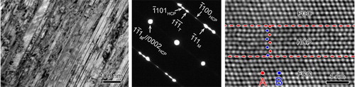
Apart from the formation of profuse nanotwins and stacking faults as shown in Figure (a), an HCP structure in the form of thin layers also formed as evidenced by weak diffraction streaks pointed by two arrows in the inset SEAD pattern, implying FCC–to–HCP phase transformation in the FeCoCrNi HEA when deformed at 77 K. The HRTEM image in Figure (b) clearly indicated the formation of an HCP phase with the ABAB stacking sequence. Based on the SAED pattern, the orientation relationship between the two phases is and
, which is the same as that observed in a medium-entropy CoCrNi alloy [Citation29] and an FeCoCrNiMn HEA [Citation23,Citation24]. However, unlike the HCP structure formed within the nanotwin leading to nanotwin–HCP lamellar composite structure in CoCrNi [Citation29], the formation of HCP stacking in the current alloy seems not to be necessarily along any twin boundary.
Figure 2. (a) A bright-field TEM image and a corresponding [110] electron diffraction pattern in the sample deformed at 77 K; (b) an HRTEM image including the ABAB HCP stacking sequence.
![Figure 2. (a) A bright-field TEM image and a corresponding [110] electron diffraction pattern in the sample deformed at 77 K; (b) an HRTEM image including the ABAB HCP stacking sequence.](/cms/asset/d5ebae38-45e3-4f64-9627-92990390021a/tmrl_a_1434250_f0002_c.jpg)
As mentioned above, when the alloys was deformed at extremely low temperature of 4.2 K, a higher density of nanotwins and stacking faults was detected, as exhibited in Figure (a). Additionally, the amount of the HCP phase also increased although the tensile strain of the sample deformed at 4.2 K was slightly lower than that at 77 K, which is demonstrated by the stronger and separated diffraction spots in Figure (b). According to the SAED pattern containing the FCC and HCP phases, their lattice parameters were approximately calculated as follows. The longitudinal planar boundary between the two phases is the
, i.e. a close packed plane in the FCC lattice and the basal plane of the HCP structure, and then the atomic planar spacing of the
is identical to that of
, which is averaged to be 0.202 nm from measuring in more than ten SAED patterns such as that in Figure (b). Thus,
and
were calculated to be 0.350 nm and 0.404 nm, respectively. Based on
and the measured
,
is determined to be 0.247 nm. Therefore, the experimental lattice constants of FCC and HCP FeCoCrNi agree very well with those obtained via ab initio simulations (
= 0.349 nm,
= 0.249 nm,
= 0.398 nm) [Citation30]. In some local regions, a large amount of HCP stacking with the two-layer period was observed, as marked by ellipses in Figure (c). The high resolution HAADF STEM image in Figure (d) was obtained in another area to reveal the atomic structure of HCP, indicating 8 atomic layers of HCP lamellae bounded by the FCC structure. Although lowering deformation temperature promotes the FCC–to–HCP transformation, the total amount of HCP phase in the whole sample is still not significant, which makes it extremely challenging to quantifiy the volume fraction of the HCP phase.
Figure 3. (a) A bright-field TEM image in the specimen deformed at 4.2 K; (b) corresponding electron diffraction pattern along the [110] zone axis; (c) a bright-field TEM image in a local region showing a large amount of the HCP phase as indicated with red ovals; (d) a HAADF STEM image including 8 layers HCP stacking.
![Figure 3. (a) A bright-field TEM image in the specimen deformed at 4.2 K; (b) corresponding electron diffraction pattern along the [110] zone axis; (c) a bright-field TEM image in a local region showing a large amount of the HCP phase as indicated with red ovals; (d) a HAADF STEM image including 8 layers HCP stacking.](/cms/asset/12de5559-2fa8-4a59-a0e2-d16e48dff414/tmrl_a_1434250_f0003_c.jpg)
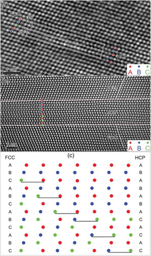
Figure (a) shows a typical high-resolution HAADF STEM image of an FCC/HCP interfacial region viewed along the direction, which was taken from the same sample of Figure . Clearly, HCP laths formed via the glide of Shockley partial dislocations with Burgers vectors of
on every other
planes. It should be mentioned that the Burgers vectors of those Shockley partials may not be the same. In the transitional zone, two adjacent Burgers circuits were drawn and the nature of the partials was identified to be a 30° Shockley partial and a 90° Shockley partial. In fact, there are three types of Shockley partials on each
plane. Although it is not possible to differentiate stacking faults caused by the motion of all the three types of Shockley partials [Citation31], the components of the Burgers vectors of these partials along
direction are different. In addition to a single type of HCP stacking in Figures (d) and (a), two kinds of stacking sequences can coexist. Figure (b) presents an example, in which a 12-layer HCP lamella comprises a 6-layer ABAB stacking and a 6-layer ACAC stacking. It is well known that an FCC structure with the ABC stacking sequence can be transformed into an HCP structure with the AB stacking sequence via the correlating glide of Shockley partials shearing the FCC matrix on every other {111} plane. However, when the gliding of one Shockley partial occurred on an adjacent {111} plane, the stacking sequence of subsequent HCP lattice changes, leading to the coexistence of two kinds of HCP stacking sequences. As schematically illustrated in Figure (c), every horizontal line represents the gliding of one Shockey partial and the gliding of the illustrated 6 partials would transform 12 layers of FCC into 6-layer ABAB stacking and 6-layer ACAC stacking, just as detected in Figure (b).
Figure 4. (a) A high-resolution HAADF STEM image exhibiting FCC transforming to HCP; (b) a high-resolution HAADF STEM image illustrating 12 layers of HCP stacking including ABAB and ACAC sequences; (c) Schematic illustration of the phase transformation mechanism from 12-layer ABC stacking to 6-layer ABAB and 6-layer ACAC stacking.
Based on the nature of FCC and HCP lattices, the HCP structure can be readily transformed locally from the FCC structure by introducing stacking faults [Citation23,Citation31]. Therefore, the SFE of materials, which represents the energy associated with interrupting the normal stacking sequence of a crystal plane [Citation32], plays a significant role in the FCC–to–HCP transformation. Very small or negative SFE has been regarded as the crucial indicator of TRIP phenomena, while a low SFE (∼20–25 mJ m−2) of FeCoCrNi HEA has been confirmed experimentally [Citation33] and theoretically [Citation30,Citation34]. Recently ab initio calculations predicted a large positive temperature dependence of the SFE of HEAs and proposed that the SFE of the current alloy is negative at 0 K [Citation25,Citation30]. Therefore, lowering the deformation temperature significantly promotes the occurrence of this polymorphic phase transformation, especially when the temperature is down to 4.2 K. In addition, theoretical investigations have revealed that the HCP structure is more stable than the FCC structure due to the low free energy [Citation16,Citation30,Citation32]. All these results manifest that the formation of the HCP structure in the FCC structure is energetically favourable and it should occur extensively at low temperatures although external thermal or mechanical stimulation is needed to overcome the transformation barrier. However, in experiments at ambient pressure, the HCP structure has not been observed so far in the FeCoCrNiMn HEA, whose SFE is even slightly lower than that of FeCoCrNi HEA [Citation33,Citation34], either at room temperature or at cryogenic temperatures down to 77 K. The volume fraction of the HCP phase in a medium-entropy CoCrNi alloy, whose SFE was also determined to be negative at 0 K [Citation30], was estimated to be around only ∼ 3% in samples deformed to 53% true tensile strain at 77 K [Citation29]. In the current study, the quantity of the HCP phase is still not significant in the whole sample even at the extremely low temperature of 4.2 K, although a high density of HCP thin layers can be detected in some local areas, which may due to the high stress/strain localisation and need further investigations.
The difference about the FCC–to–HCP transformation in HEAs between experimental and theoretical investigations suggests the kinetic limitation of phase transformation under experimental conditions. In fact, the free energies of different crystal structures determined using ab initio calculations are related to thermodynamic ground state only [Citation16]. However, the deformation behaviour of materials including dislocation gliding, deformation twinning and phase transformation is predominantly governed by the entire generalised stacking fault energy (GSFE) curve (γ-surface) [Citation35,Citation36]. It was suggested that the γ-surface of HEAs might be sophisticated due to the compositional complexity, which hinders kinetically the phase transformation [Citation16,Citation34]. Moreover, the formation of short-range order in the massive solid solutions, reflected by the large friction stress, also affects the phase transformation since additional energy is required for the movement of Shockley partials to break the ordered region [Citation5]. Details of the mechanism behind the difficulty of the displacive FCC–HCP phase transformation in HEAs even at cryogenic temperatures need to be further investigated. Nevertheless, the formation of the HCP phase should be beneficial for the improvement of strength and work hardening behaviour by restricting dislocation slip and accommodating plastic strains [Citation18,Citation29]. Although applying high-pressure seems to be more powerful to promote the transformation than lowering the temperature [Citation23,Citation24], pressure and temperature are essential parameters that can induce the polymorphic transformation by altering the atomic and/or electronic structures. Therefore, the combination of high pressure and low temperature can be employed to manipulate the microstructures and phases of HEAs to precisely control their mechaincal properties and then broaden their potential applications.
4. Conclusions
The cryogenic-deformation-induced phase transformation from the FCC structure to the HCP structure in an FeCoCrNi HEA was observed. Atomic-scale investigation revealed that the HCP phase formed via the glide of Shockley partial dislocations on every other plane. Lowering the deformation temperature promotes the phase transformation. The complex γ-surface and the formation of short-range order, both of which originate from the compositional complexity of HEAs, can kinetically hinder the transformation. These discoveries enliven and enrich our understanding of the deformation behaviour and phase stability of HEAs at cryogenic temperatures.
Acknowledgements
The authors acknowledge the scientific and technical input and support from the Australian Microscopy & Microanalysis Research Facility node at the University of Sydney and the assistance of Dr. David Mitchell of the Electron Microscopy Centre of the University of Wollongong.
Disclosure statement
No potential conflict of interest was reported by the authors.
Additional information
Funding
References
- Yeh JW, Chen SK, Lin SJ, et al. Nanostructured high-entropy alloys with multiple principal elements: novel alloy design concepts and outcomes. Adv Eng Mater. 2004;6:299–303. doi: 10.1002/adem.200300567
- Zhang Y, Zuo TT, Tang Z, et al. Microstructures and properties of high-entropy alloys. Prog Mater Sci. 2014;61:1–93. doi: 10.1016/j.pmatsci.2013.10.001
- Tsai M-H, Yeh J-W. High-entropy alloys: A critical review. Mater Res Lett. 2014;2:107–123. doi: 10.1080/21663831.2014.912690
- Miracle DB, Senkov ON. A critical review of high entropy alloys and related concepts. Acta Mater. 2017;122:448–511. doi: 10.1016/j.actamat.2016.08.081
- Otto F, Dlouhý A, Somsen C, et al. The influences of temperature and microstructure on the tensile properties of a CoCrFeMnNi high-entropy alloy. Acta Mater. 2013;61:5743–5755. doi: 10.1016/j.actamat.2013.06.018
- Gludovatz B, Hohenwarter A, Catoor D, et al. A fracture-resistant high-entropy alloy for cryogenic applications. Science. 2014;345:1153–1158. doi: 10.1126/science.1254581
- Wu Z, Gao YF, Bei H. Single crystal plastic behavior of a single-phase, face-center-cubic-structured, equiatomic FeNiCrCo alloy. Scripta Mater. 2015;109:108–112. doi: 10.1016/j.scriptamat.2015.07.031
- Senkov ON, Scott JM, Senkova SV, et al. Microstructure and room temperature properties of a high-entropy TaNbHfZrTi alloy. J Alloy Compd. 2011;509:6043–6048. doi: 10.1016/j.jallcom.2011.02.171
- Zou Y, Maiti S, Steurer W, et al. Size-dependent plasticity in an Nb25Mo25Ta25W25 refractory high-entropy alloy. Acta Mater. 2014;65:85–97. doi: 10.1016/j.actamat.2013.11.049
- Zou Y, Ma H, Spolenak R. Ultrastrong ductile and stable high-entropy alloys at small scales. Nat Commun. 2015;6:7748. doi: 10.1038/ncomms8748
- Yusenko KV, Riva S, Carvalho PA, et al. First hexagonal close packed high-entropy alloy with outstanding stability under extreme conditions and electrocatalytic activity for methanol oxidation. Scripta Mater. 2017;138:22–27. doi: 10.1016/j.scriptamat.2017.05.022
- Feuerbacher M, Heidelmann M, Thomas C. Hexagonal high-entropy alloys. Mater Res Lett. 2015;3(1):1–6. doi: 10.1080/21663831.2014.951493
- Youssef KM, Zaddach AJ, Niu C, et al. A novel Low-density, high-hardness, high-entropy alloy with close-packed single-phase nanocrystalline structures. Mater Res Lett. 2015;3:95–99. doi: 10.1080/21663831.2014.985855
- Zhang Z, Mao MM, Wang J, et al. Nanoscale origins of the damage tolerance of the high-entropy alloy CrMnFeCoNi. Nature Comm. 2015;6:10143. doi: 10.1038/ncomms10143
- Lin Q, An X, Liu H, et al. In-situ high-resolution transmission electron microscopy investigation of grain boundary dislocation activities in a nanocrystalline CrMnFeCoNi high-entropy alloy. J Alloy Compd. 2017;709:802–807. doi: 10.1016/j.jallcom.2017.03.194
- Ma D, Grabowski B, Körmann F, et al. Ab initio thermodynamics of the CoCrFeMnNi high entropy alloy: importance of entropy contributions beyond the configurational one. Acta Mater. 2015;100:90–97. doi: 10.1016/j.actamat.2015.08.050
- Deng Y, Tasan CC, Pradeep KG, et al. Design of a twinning-induced plasticity high entropy alloy. Acta Mater. 2015;94:124–133. doi: 10.1016/j.actamat.2015.04.014
- Li Z, Pradeep KG, Deng Y, et al. Metastable high-entropy dual-phase alloys overcome the strength–ductility trade-off. Nature. 2016;534:227–230. doi: 10.1038/nature17981
- Li Z, Tasan CC, Pradeep KG, et al. A TRIP-assisted dual-phase high-entropy alloy: grain size and phase fraction effects on deformation behavior. Acta Mater. 2017;131:323–335. doi: 10.1016/j.actamat.2017.03.069
- Lilensten L, Couzinié J-P, Bourgon J, et al. Design and tensile properties of a BCC Ti-rich high-entropy alloy with transformation-induced plasticity. Mater Res Lett. 2017;5:110–116. doi: 10.1080/21663831.2016.1221861
- Laurent-Brocq M, Akhatova A, Perrière L, et al. Insights into the phase diagram of the CrMnFeCoNi high entropy alloy. Acta Mater. 2015;88:355–365. doi: 10.1016/j.actamat.2015.01.068
- Otto F, Dlouhý A, Pradeep KG, et al. Decomposition of the single-phase high-entropy alloy CrMnFeCoNi after prolonged anneals at intermediate temperatures. Acta Mater. 2016;112:40–52. doi: 10.1016/j.actamat.2016.04.005
- Zhang F, Wu Y, Lou H, et al. Polymorphism in a high-entropy alloy. Nat Commun. 2017;8:15687. doi: 10.1038/ncomms15687
- Tracy CL, Park S, Rittman DR, et al. High pressure synthesis of a hexagonal close-packed phase of the high-entropy alloy CrMnFeCoNi. Nat Commun. 2017;8:15634. doi: 10.1038/ncomms15634
- Huang S, Li W, Lu S, et al. Temperature dependent stacking fault energy of FeCrCoNiMn high entropy alloy. Scripta Mater. 2015;108:44–47. doi: 10.1016/j.scriptamat.2015.05.041
- An XH, Lin QY, Sha G, et al. Microstructural evolution and phase transformation in twinning-induced plasticity steel induced by high-pressure torsion. Acta Mater. 2016;109:300–313. doi: 10.1016/j.actamat.2016.02.045
- Liu JP, He ZB, Lin QY, et al. Outstanding tensile ductility of high entropy CrFeCoNi alloy at extremely low temperatures. Unpublised result.
- Laplanche G, Kostka A, Horst OM, et al. Microstructure evolution and critical stress for twinning in the CrMnFeCoNi high-entropy alloy. Acta Mater. 2016;118:152–163. doi: 10.1016/j.actamat.2016.07.038
- Miao J, Slone CE, Smith TM, et al. The evolution of the deformation substructure in a Ni-Co-Cr equiatomic solid solution alloy. Acta Mater. 2017;132:35–48. doi: 10.1016/j.actamat.2017.04.033
- Zhang YH, Zhuang Y, Hu A, et al. The origin of negative stacking fault energies and nano-twin formation in face-centered cubic high entropy alloys. Scripta Mater. 2017;130:96–99. doi: 10.1016/j.scriptamat.2016.11.014
- Yang X-S, Sun S, Ruan H-H, et al. Shear and shuffling accomplishing polymorphic fcc γ → hcp ε → bct α martensitic phase transformation. Acta Mater. 2017;136:347–354. doi: 10.1016/j.actamat.2017.07.016
- Zhao S, Stocks GM, Zhang Y. Stacking fault energies of face-centered cubic concentrated solid solution alloys. Acta Mater. 2017;134:334–345. doi: 10.1016/j.actamat.2017.05.001
- Zaddach AJ, Niu C, Koch CC, et al. Mechanical properties and stacking fault energies of NiFeCrCoMn high-entropy alloy. JOM. 2013;65:1780–1789. doi: 10.1007/s11837-013-0771-4
- Beyramali Kivy M, Asle Zaeem M. Generalized stacking fault energies, ductilities, and twinnabilities of CoCrFeNi-based face-centered cubic high entropy alloys. Scripta Mater. 2017;139:83–86. doi: 10.1016/j.scriptamat.2017.06.014
- Kibey S, Liu JB, Curtis MJ, et al. Effect of nitrogen on generalized stacking fault energy and stacking fault widths in high nitrogen steels. Acta Mater. 2006;54:2991–3001. doi: 10.1016/j.actamat.2006.02.048
- Zhu YT, Liao XZ, Wu XL. Deformation twinning in nanocrystalline materials. Prog Mater Sci. 2012;57:1–62. doi: 10.1016/j.pmatsci.2011.05.001