
ABSTRACT
Deformation behavior of a harmonic structured material (HSM), core–shell 304L stainless steel, is investigated using micro-digital image correlation (micro-DIC). High strain-partitioning between core and shell is observed. Because the grain boundaries with a grain-size gradient in HSM induce high deformation-incompatibility, strain peaks are detected near core–shell boundaries and in grain boundaries of cores. This incompatibility is compensated by geometrically necessary dislocations, generating back stress. The back stress is measured using tensile unloading-reloading testing. This investigation demonstrates higher back stress and strain hardening rate in HSMs than homogeneous materials, resulting in enhanced ductility.
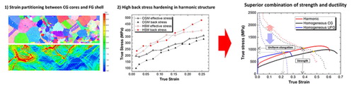
GRAPHICAL ABSTRACT
IMPACT STATEMENT
Core–shell structure with grain size gradient leads to strain partitioning and high back stress hardening in HSMs. micro-DIC was utilized to observe the local strain distribution.
Grain refinement is a common method used to strengthen metallic materials. Among the many techniques utilized to refine grains, severe plastic deformation (SPD) is well-known for its ability to generate very small grains, by imposing large strains [Citation1–3]. However, the resulting materials with ultrafine-grained (UFG) structures exhibit significantly lower ductility compared to coarse-grained (CG) counterparts, at the expense of higher strength. As a result, homogeneous UFG materials lack the superior combination of strength and ductility, i.e. high toughness, which is critical to the performance of structural materials.
To solve this ductility problem, many researchers have recently tried to create heterogeneous microstructures, which exhibit not only high strength but also reasonable ductility [Citation4–7]. The strength and ductility of the heterogeneous structured materials are usually in between those of the CG and UFG materials, simply by the rule-of-mixtures (ROM). However, sometimes they exhibit a higher combination of strength and ductility than can be expected by ROM, due to their ‘heterogeneity’. Recently, this synergetic effect has been widely reported for heterogeneous structures [Citation8–11].
As a way of manufacturing bulk materials with heterogeneous structures, Ameyama et al. proposed a new microstructure, called a ‘harmonic structure’ (HS) [Citation12–14]. This way of manufacturing has the advantage of being able to control the fraction and even spatial distribution of the CG and UFG areas. The HS manufacturing process integrates the SPD and powder metallurgy (PM) approaches: HS is manufactured by the hot consolidation of bimodal powders created by controlled surface plastic deformation, such as ball milling or jet milling. The coarse grains on the inside of the milled powders remain as CG areas (cores) after consolidation, while the fine grains on the surface of the milled powders form a matrix of a three-dimensionally continuously connected network (shell). As a result, HS has a unique three-dimensional heterogeneous structure, where CG cores are homogeneously distributed in UFG shells in all directions.
Recently, harmonic structured materials (HSMs) were investigated in metals and alloys such as pure titanium, SUS304L, and Co-Cr-Mo, and showed superior mechanical properties to their homogeneous counterparts [Citation12–14]. The recent research [Citation14] suggests a possible deformation mechanism to explain the exclusive deformation behavior of the HSM. According to the explanation, to accommodate the overall shape change in the specimens, the plastic deformation also brings about shape change to the CG core regions together with the UFG shell network. At this moment, the relatively hard UFG shell structure becomes the high stress area, which takes charge of high strength. The soft CG core regions carry higher strains, retaining high ductility. However, this explanation isn’t far from the general deformation mechanism of the composite with soft/hard phases, e.g. dual phase (DP) steel. To understand the unique deformation behavior of HSM, the analysis based on the quantitative experimental results should be performed.
The present paper is focused on explaining how HSM preserves ductility but has higher strength than the homogeneous CG material (CGM), by observing its unusual deformation behavior. HS and homogeneous CG specimens of SUS304L steel were employed for the experiment. Micro-digital image correlation (micro-DIC) using a silver nanoscale pattern was utilized to observe the strain distribution in the HSM during deformation, and back stress was measured by unloading-reloading tests. From the experiment results, a mechanism to account for the high ductility induced by strain partitioning and back stress hardening in HSM is suggested.
SUS304L steel powders were produced using a plasma rotating electrode process and their chemical composition is shown in Table . The average particle size of the initial powders was 120 μm, measured using SALD-2300, the Shimadzu’s laser diffraction particle size analyzer. To manufacture the bimodal grain sized powders for HSMs, mechanical milling was performed using a Fritch P-5 planetary ball mill, with SUS304L balls (5 mm diameter) and pot (500 ml). The mechanical milling was performed in Ar atmosphere, while the ball-to-powder weight ratio was kept as 2:1. The powders were milled for 180 ks, with a rotation speed of 200 rpm.
Table 1. Chemical composition of manufactured SUS304L powders (mass %).
After the mechanical milling, spark plasma sintering (SPS) in a 1223 K vacuum state with 50 MPa pressure, followed by furnace cooling, was performed to make the bulk. A bulk material with a homogeneous CG structure was manufactured under the same SPS condition, except a higher temperature (1373 K). The lower sintering temperature for the HSM is due to the low superplasticity-temperature in UFG materials, which helps sintering in SPS.
To evaluate the mechanical properties of the manufactured specimens, tensile tests were performed for both the HSM and homogeneous CGM specimens. The tensile test specimens had a gauge length of 1.5 mm and a cross-section area of 1 × 1 mm2, and the strain rate was 1.0 × 10⁻³ s−1.
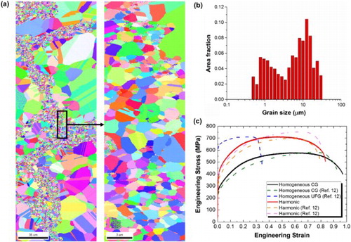
Figure shows general information about the HSM manufactured in the conditions above. Electron backs-cattering diffraction (EBSD) images demonstrate the microstructure of the HSM. The inverse pole figure (IPF) EBSD map of the HSM, Figure (a), shows a clear CG core-UFG shell structure. The grain size distribution, Figure (b), confirms the bimodality. Figure (c) shows the engineering stress–strain curves of the bulk SUS304L with various microstructures, demonstrating the HSM has a superior combination of strength and ductility compared to the homogeneous counterparts.
Figure 1. (a) IPF EBSD map of SUS304L HSM, and a magnified map of the shell region. (b) The bimodal grain size distribution of HSM. (c) Engineering stress-strain curves of bulk SUS304L with various microstructures.
To observe the strain distribution in the HSM after elongation, tensile tests were performed with micro-DIC, a precise method to measure the strain gained by deformation. For accurate strain calculation in micro-DIC, clear nanoscale patterns need to first be created on the specimen surface. In this experiment, silver nanodot patterning was performed on the tensile specimens. 15 nm of silver layer was deposited on the specimen using the SNTECK sputtering system, then rapid thermal annealing was conducted for 5 min at 300°C, to induce the agglomeration of silver as a speckle pattern.
After the patterning, EBSD images of the tensile specimens were taken to find the proper spots for the DIC SEM images, and to compare the microstructures and the DIC results. The SEM images were taken at a magnification enough to recognize the pattern, for the initial state of DIC calculation. Then, the tensile tests were performed to 10% elongation under the same conditions as above. After the elongation, SEM images were taken again at the same spots to compare with the initial pattern. Lastly, the strain distribution in the HSM after the elongation was calculated using the commercial DIC software, GOM Correlate.
Figure shows the von Mises equivalent plastic strain distribution in HSM after 10% elongation, calculated by DIC. The red boxes in Figure (a) refer to the DIC calculated spots, and Figure (b) shows the DIC results for each spot after 10% elongation. In comparison to the microstructures in the IPF map, the DIC results show clear strain partitioning along the core–shell boundary. More strain is concentrated on the CG area than the UFG area, which carries a much lower strain than the average. This deformation behavior is also observed in other materials with bimodal grain-size distributions [Citation15,Citation16]. In bimodal structure, the extensive plastic deformation in the CG area not only contributes to the global ductility, but also releases stress concentrations and avoids the early fracture of the sample. According to the previous research [Citation16], the UFG matrix in Al-Mg bimodal structure exhibits clear dislocation activities, while the monolithic UFG alloy exhibits very little plastic strain without extensive dislocation activities during plastic deformation. In the same manner, strain partitioning between CG cores and UFG shell makes an advantage on the ductility.
Figure 2. (a) EBSD IPF map of SUS304L HSM at the initial state. The red boxes refer to the regions where DIC analysis was conducted after 10% elongation. (b) Equivalent plastic strain distribution of HSM after 10% elongation, calculated by the DIC analysis. (c) The schematic diagram of HSM microstructure and dislocation generations. (d) Strain profile along the path, which exhibits strain peaks near core-shell boundaries.
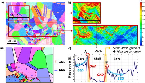
In the plastic strain profiles along the paths at Figure (d), strain peaks are observed near the boundaries between the cores and the shell (points A and B). The origin of these strain peaks near the boundaries are geometrically necessary dislocations (GNDs). Ashby [Citation17] proposed the existence of GNDs, which accommodate the deformation gradients to keep compatibility among neighboring grains or phases. GNDs are distinguished from the statistically stored dislocations (SSDs) which accumulate in single crystals during straining. Except the single-phase single crystals, almost all metals are plastically non-homogeneous, so have some extent of GNDs.
The effect of GNDs is extended in heterogeneous structures or multi-phase alloys such as DP steel because the deformation is heterogeneous not only on local but also on global scale [Citation18,Citation19], Generally, GNDs are generated near grain boundaries to maintain the physical continuity between neighboring grains of different orientations because the directions of their slip systems are different. In DP steel, the deformation gradient is very high along the ferrite-martensite interfaces due to the difference in mechanical properties. In the case of HSM, the deformation gradient on global scale appears along the core–shell boundary, since there are differences in mechanical properties caused by different grain sizes between the cores and the shell. This leads especially to high plastic incompatibility along core–shell boundaries, so the strain peaks are observed.
Figure (c) exhibits the schematic diagram of dislocation generations in HSM. In light of the plastic strain distribution in Figure (b), most of dislocations should be generated in the CG core regions rather than UFG shell. This result is coherent with previous studies [Citation18,Citation19] that the plasticity begins near the soft phase, where the dislocations are easily generated. The dislocations generated on the cores by simple work hardening are SSDs. There are clear gaps in strain values between neighboring cores and shell, so the GNDs are created by the need to maintain contact between the two regions during plastic deformation. Therefore, the steep strain gradients are created near core–shell boundaries as shown in Figure (d), and create high stress regions [Citation20].
GNDs contribute to hardening not only by acting as individual obstacles to slip like SSDs, but also by creating a long-range back stress [Citation17]. Several studies [Citation10,Citation21] reported the back stress hardening in heterogeneous structures, such as heterogeneous lamella structure. According to the research, the heterogeneous microstructure creates larger amount of GNDs due to the higher plastic incompatibility at the same deformation level. From the steep strain partitioning observed by micro-DIC, it can be assumed that the back stress hardening would be high in HSM.
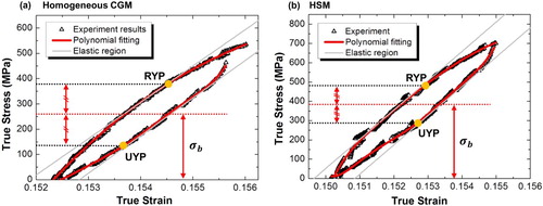
To measure the back stress values generated during deformation, unloading-reloading tests were performed on both the HSM and homogeneous CGM counterpart. Each specimen was repeatedly loaded and unloaded while the strain was steadily increased in small increments. Figure exhibits a single unloading-reloading loop for a particular strain with the homogeneous CGM and HSM. The method to calculate back stress () using an unloading-reloading loop is referred to Yang et al. [Citation21], as follows:
where
is the unloading yield stress and
is the reloading yield stress. Each yield point is defined as the point which has a 10% reduction in slope from the effective elastic modulus. In order to clearly define the yield point, every loop is fitted as a polynomial function. Note that the back stress is much stronger in the HSM than in the homogeneous CGM in a similar strain region in Figure .
Figure 3. The unloading-reloading loops for (a) homogeneous CGM and (b) HSM. Each loop is fitted as a polynomial function, and the yield point is defined as the point which has a 10% reduction in slope from the effective elastic modulus.
Figures (a) and 4(b) represent the back stress measured using the unloading-reloading loops in the true strain range of 0 to 25%, for the homogeneous CGM and the HSM, respectively. The back stress increases as strain increases in both cases, indicating that the GNDs steadily pile up during the deformation. The HSM exhibits higher back stress than the homogeneous CGM over this whole strain range, which suggests that more GNDs are concentrated at the grain boundaries in the HSM. However, it should be noted that HSM inherently has a higher yield strength than the homogeneous CGM, which means a comparison of the absolute values of back stress is less meaningful. To consider this inherent difference, the comparison between the back stress and the effective stress is shown in Figure (c). Note that the effective stress is commonly defined as the value obtained by subtracting the back stress from the flow stress. It clearly shows that the contribution of back stress during deformation is still higher in the HSM than in the homogeneous CGM, even considering the difference in yield stress.
Figure 4. The back stress measured using the unloading-reloading test for (a) homogeneous CGM and (b) HSM. The HSM exhibits a higher back stress than the homogeneous CGM over the whole strain range. (c) Comparison between back stress and effective stress for HSM and CGM. (d) The strain hardening rates for harmonic and homogeneous structures. The higher strain hardening rate due to back stress hardening in the HSM expands the uniform elongation.
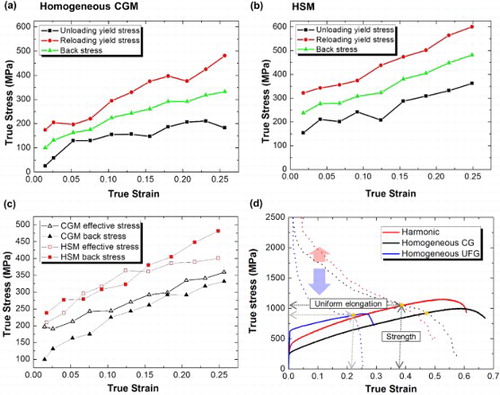
Generally, when a material is strengthened by grain refinement, the higher grain boundary fraction serves as an additional obstacle to dislocation movement. The grain boundary causes not only high strength but also a lower accumulation of dislocation capacity, resulting in a drastically reduced strain hardening rate. For this reason, the strain hardening rate curve of homogeneous UFG materials intersects the stress–strain curve very quickly, as shown in Figure (d).
On the other hand, the strain hardening rate of the HSM is higher than that of the homogeneous CGM in the early stage, even though the HSM also exhibits a higher yield strength. It delays the intersection of the strain hardening rate curve and stress–strain curve, resulting in a long uniform elongation. As the result, HSM exhibits not only the higher uniform elongation but also higher ultimate tensile strength than UFG materials. The high strain hardening rate of the HSM can be explained by (i) strain partitioning and (ii) back stress hardening.
The DIC result in Figure (b) reveals that the coarse grains in the cores carry high strain, instead of the fine grains in the shell. This indicates that the strain hardening in the whole structure is dominated by the coarse grains in the early stage of deformation. Therefore, the strain hardening rate curve of the HSM has a similar aspect as that of the homogeneous CGM; see Figure (d). Note that the amount of strain hardening in the coarse grains of the HSM is higher than that in the homogeneous CGM for the same global strain, because they actually carry a higher strain than the global strain.
Another reason for the high strain hardening rate in HSM is back stress hardening, because the HSM exhibits higher back stress than homogeneous materials over the wide strain range. This is related, not to the overall strain partitioning between the cores and shell, but to the strain peaks observed near the grain boundaries. The core–shell boundaries among grains with very different sizes lead to high plastic incompatibility during deformation, and finally lead to the dense GNDs near boundaries, and high back stress.
In summary, the unique deformation behavior of SUS304L HSM was investigated using micro-DIC and unloading-reloading tests. Clear strain partitioning bet-ween the coarse grains in the cores and the fine grains in the shell was observed during deformation, and strain peaks were found near the core–shell boundaries. These strain peaks resulted from the GNDs piled up near the grain boundaries, which leads to a high back stress hardening. Compared to the homogeneous CGM counterpart, the HSM exhibited higher back stress over the whole strain range.
Due to the effect of strain partitioning and back stress hardening, the HSM attains an even higher strain hardening rate than the homogeneous CGM, unlike the general tendency for grain refinement. It should be noted that the strain localized area in a heterogeneous structure generally plays an important role in back stress hardening, but can be a critical point of failure at the same time. To optimize the mechanical properties of various heterogeneous materials, a quantitative study to determine whether this strain localized area has a net positive effect or the opposite should be pursued as further work.
Disclosure statement
No potential conflict of interest was reported by the authors.
ORCID
Hyoung Seop Kim http://orcid.org/0000-0002-3155-583X
Additional information
Funding
Related Research Data
References
- Estrin Y, Vinogradov A. Extreme grain refinement by severe plastic deformation: a wealth of challenging science. Acta Mater. 2013;61:782–817. doi: 10.1016/j.actamat.2012.10.038
- Sabirov I, Murashkin MY, Valiev RZ. Nanostructured aluminium alloys produced by severe plastic deformation: new horizons in development. Mater Sci Eng A. 2013;560:1–24. doi: 10.1016/j.msea.2012.09.020
- Kim HS, Seo MH, Hong SI. Plastic deformation analysis of metals during equal channel angular pressing. J Mater Process Technol. 2001;113:622–626. doi: 10.1016/S0924-0136(01)00710-5
- Ma E, Zhu T. Towards strength–ductility synergy through the design of heterogeneous nanostructures in metals. Mater Today (Kidlington). 2017;20:323–331. doi: 10.1016/j.mattod.2017.02.003
- Kang JY, Kim JG, Kim SK, et al. Outstanding mechanical properties of high-pressure torsion processed multiscale TWIP-cored three layer steel sheet. Scripta Mater. 2016;123:122–125. doi: 10.1016/j.scriptamat.2016.06.009
- Lu K. Making strong nanomaterials ductile with gradients. Science. 2014;345:1455–1456. doi: 10.1126/science.1255940
- Fang TH, Li WL, Tao NR, et al. Revealing extraordinary intrinsic tensile plasticity in gradient nano-grained copper. Science. 2011;331:1587–1590. doi: 10.1126/science.1200177
- Bouaziz O, Bréchet Y, Embury JD. Heterogeneous and architectured materials: a possible strategy for design of structural materials. Adv Eng Mater. 2008;10:24–36. doi: 10.1002/adem.200700289
- Ashby M. Designing architectured materials. Scripta Mater. 2013;68:4–7. doi: 10.1016/j.scriptamat.2012.04.033
- Wu X, Yang M, Yuan F, et al. Heterogeneous lamella structure unites ultrafine-grain strength with coarse-grain ductility. Proc Natl Acad Sci USA. 2015;112:14501–14505. doi: 10.1073/pnas.1517193112
- Wang Y, Chen M, Zhou F, et al. High tensile ductility in a nanostructured metal. Nature. 2002;419:912–915. doi: 10.1038/nature01133
- Zhang Z, Vajpai SK, Orlov D, et al. Improvement of mechanical properties in SUS304L steel through the control of bimodal microstructure characteristics. Mater Sci Eng A. 2014;598:106–113. doi: 10.1016/j.msea.2014.01.023
- Vajpai SK, Sawangrat C, Yamaguchi O, et al. Effect of bimodal harmonic structure design on the deformation behaviour and mechanical properties of Co-Cr-Mo alloy. Mater Sci Eng C. 2016;58:1008–1015. doi: 10.1016/j.msec.2015.09.055
- Vajpai SK, Ota M, Zhang Z, et al. Three-dimensionally gradient harmonic structure design: an integrated approach for high performance structural materials. Mater Res Lett. 2016;4:191–197. doi: 10.1080/21663831.2016.1218965
- Witkin D, Lee Z, Rodriguez R, et al. Al–Mg alloy engineered with bimodal grain size for high strength and increased ductility. Scripta Mater. 2003;49:297–302. doi: 10.1016/S1359-6462(03)00283-5
- Fan GJ, Choo H, Liaw PK, et al. Plastic deformation and fracture of ultrafine-grained Al–Mg alloys with a bimodal grain size distribution. Acta Mater. 2006;54:1759–1766. doi: 10.1016/j.actamat.2005.11.044
- Ashby MF. The deformation of plastically non-homogeneous materials. Philos Mag. 1970;21:399–424. doi: 10.1080/14786437008238426
- Yan D, Tasan CC, Raabe D. High resolution in situ mapping of microstrain and microstructure evolution reveals damage resistance criteria in dual phase steels. Acta Mater. 2015;96:399–409. doi: 10.1016/j.actamat.2015.05.038
- Kundu A, Field DP. Influence of plastic deformation heterogeneity on development of geometrically necessary dislocation density in dual phase steel. Mater Sci Eng A. 2016;667:435–443. doi: 10.1016/j.msea.2016.05.022
- Wu X, Zhu Y. Heterogeneous materials: a new class of materials with unprecedented mechanical properties. Mater Res Lett. 2017;5:527–532. doi: 10.1080/21663831.2017.1343208
- Yang M, Pan Y, Yuan F, et al. Back stress strengthening and strain hardening in gradient structure. Mater Res Lett. 2016;4:145–151. doi: 10.1080/21663831.2016.1153004