
ABSTRACT
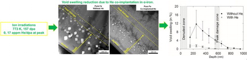
Effect of helium on void swelling was studied in high-purity α-iron, irradiated using energetic self-ions to 157 displacements per atom (dpa) at 773 K, with and without helium co-implantation up to 17 atomic parts-per-million (appm) He/dpa. Helium is known to enhance cavity formation in metals in irradiation environments, leading to early void swelling onset. In this study, microstructure characterization by transmission electron microscopy revealed compelling evidence of dramatic swelling reduction by helium co-implantation, achieved primarily by cavity size reduction. A comprehensive understanding of helium induced cavity microstructure development is discussed using sink strength ratios of dislocations and cavities.
IMPACT STATEMENT
Reduction of void swelling by helium co-implantation is reported, highlighting that it’s not always true that swelling will be higher in metals when helium is present along with irradiation damage.
GRAPHICAL ABSTRACT
In future fusion reactors, structural steels will be exposed to high neutron damage, with dose up to 150–200 displacements per atom (dpa) at elevated temperatures up to 973 K [Citation1]. Additionally, helium generation rate by (n, α) transmutation reaction with 14 MeV neutrons is expected to be ∼10–12 atomic parts-per-million (appm) He/dpa [Citation1,Citation2]. Interaction of such large levels of helium with irradiation-induced defects will largely complicate the radiation damage scenario. It is, hence, of paramount importance that helium induced microstructure modifications, its interaction with irradiation-induced defects and its consequences on material properties be evaluated with rigour. Study of irradiation damage on simple body centred cubic (bcc) iron (α-Fe) is of special interest because it is the base element for structural steels used in the nuclear reactors. Moreover, in such model materials, the fundamentals of damage behaviour are relatively simpler to understand owing to the absence of alloying elements and impurities, known to interact strongly with radiation-induced defects [Citation3,Citation4].
Studies have shown that helium drastically degrades mechanical properties of metals and ceramics, predominantly by preferential nucleation of helium stabilized cavities on the grain boundaries at elevated temperatures [Citation5,Citation6]. This behaviour induces grain boundary weakening, developing a tendency for inter-granular cracking [Citation6]. However, the most well-known, but relatively less understood influence of helium is on the nucleation/growth of cavities which causes void swelling [Citation6,Citation7]. It is largely accepted that helium causes void swelling by facilitating cavity formation. Based on ab-initio calculations in α-Fe, which show a strong binding energy of vacancies to helium atoms and to helium-vacancy (He-V) clusters, it is concluded that the primary role of helium is to stabilize vacancy clusters [Citation8]. This theoretical result is experimentally validated. For example, positron lifetime measurements in Fe have shown that helium favours cavity formation as compared to hydrogen [Citation9]. Transmission electron microscopy (TEM) study of Brimbal et al.[Citation10] showed an order of magnitude increase in cavity number density in high purity α-Fe, irradiated to ∼45 dpa (Kinchin-Pease method) by 2 MeV self-ions and co-implanted with 250 and 2500 appm helium at 773 K, as compared to when no helium was implanted. However, contrary to popular belief, the average cavity size and void swelling were seen to slightly decrease upon helium addition, which were noted to be 24 nm, 0.40 ± 0.1% when no helium was present, and reduced to 10 nm, 0.31 ± 0.09% and 7.2 nm, 0.2 ± 0.06% with 250 and 2500 appm helium, respectively. Similar results were noted by Kuramoto et al. [Citation11] in Fe at 723 and 773 K after single and dual beam irradiations to 50 dpa, ∼10 appm He/dpa, using 4 MeV Ni ions and a continuous energy varying helium ion beam. But swelling suppressive effect of helium in both these studies remained small, which we believe is due to low initial swelling levels, and hence necessitates in-depth study after much higher doses. Apart from these studies, to the best of our knowledge, a detailed analysis of void swelling behaviour induced by helium during ion irradiations on high purity α-Fe is not available in the literature. However, a large void swelling data set after ion and neutron irradiations is present for steels and other metallic materials where in majority of the cases enhanced void swelling occurred due to helium [Citation12–18] and in some other cases reduced swelling was observed [Citation10,Citation11,Citation19–21]. This symbolizes that helium may both increase or decrease swelling. Nevertheless, swelling increase due to helium can be well explained because helium would nucleate cavities, but not the contrary.
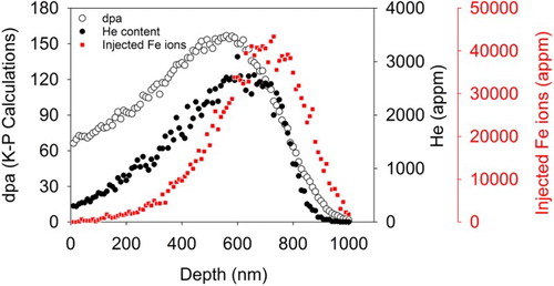
To well-understand the role of helium on void swelling, we have performed dedicated ion irradiation experiments on a very-high purity α-Fe to high dose (>100 dpa) at 773 K with and without simultaneous helium implantation. The material was produced at Ecole des Mines de Saint Etienne in France and received in recrystallized state after 70% cold reduction, followed by 1 hour-973 K annealing under argon flow and air cooling to room temperature. The resulting mean grain size was 183 μm and dislocation density was of the order of 1012 m−2. Ion irradiations were performed on 100 μm thick electropolished dimpled discs, at JANNuS multi-beam irradiation facility in France, using a rastered 2 MeV Fe2+ beam to reach 1.38 × 10²¹ ions.m−2. For the dual beam case, rastered and energy degraded 2 MeV He+ ions were co-implanted to reach 8.4 × 10²⁰ ions.m−2. Figure shows the damage depth profile, helium and injected self-ion profile obtained by SRIM, using a displacement threshold of 40 eV and Kinchin–Pease method26. At the damage peak (∼550–600 nm), dose, dose rate and He/dpa level were 157 dpa, ∼3.3 × 10⁻³ dpa/s and 17 appm He/dpa respectively.
Figure 1. SRIM calculations of displacement damage, helium concentration and injected self-ion concentration depth profile for Fe matrix.
After irradiations, cross-sectional focused ion beam (FIB) specimens were prepared using a FEI Helios650 Dual Beam™ FIB machine. Initial lift-out was done using 30 keV gallium ions, followed by progressive energy decrease to 2 keV for thinning. More details about impurity concentration of sample, irradiation and sample preparation is given in the supplementary material. Microstructure was characterized utilizing a LaB6 based 200 keV JEOL 2100 TEM, equipped with a Gatan Orius high resolution CCD camera and Gatan GIF Quantum spectrometer for EELS (electron energy-loss spectroscopy). Through-focal series technique [Citation22] was used to image the cavities. For the sake of simplicity, only under-focused images are presented in this article. Depth variation of void swelling was estimated by calculating the cavity volume fraction from the TEM micrographs. The error bars on cavity number density was estimated from error in sample thickness determination and statistical error in the number of cavities in analysed zone, while an additional error in cavity size determination was included for void swelling results. Specimen thickness was determined by measuring the plasmon peak intensity in EELS and utilizing the log-ratio model [Citation23]. Details about error estimation can be found in supplementary material. For faceted cavities, the diagonal was considered as size, while for spherical cavities, the size is represented by their diameter.
Figure shows bright field TEM images of cavities formed after high dose irradiations, with and without helium co-implantation. Images in Figure (a, b) taken on (001) zone axis show that most of the cavities were faceted. Figure (c, d) show the entire depth distribution of cavities in the samples, imaged away from diffraction conditions. For a better understanding, quantitative values of the depth variation of cavity size, number density and void swelling extracted from the TEM images are shown in Figure .
Figure 2. BF TEM images of cavities in α-Fe when (a) helium was co-implanted to 17 appm He/dpa at damage peak and (b) without helium co-implantation. Imaging was performed exactly on (001) zone axis, as evidenced by the diffraction patterns shown as insets. (c), (d). TEM images of depth distribution of cavities with and without helium co-implantation respectively, imaged far away from diffraction conditions. (under-focus = −1136 nm).
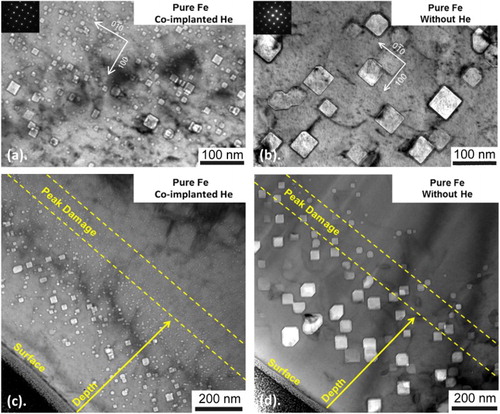
Figure 3. Depth distribution of (a) void swelling (b) average cavity size and (c) number density in α-Fe irradiated at 773 K, without and with co-implantation of helium.
Maximum difference of swelling in the two cases was noted in the region between 200–300 nm. The trend of higher average cavity size when no helium was co-implanted was true for the entire damage depth, while the sample with helium always had higher cavity number density. Since void swelling was always higher for the sample with no helium, it is evident that swelling was dominated by the cavity size and not by the number density.
From these results, it is conclusive that void swelling will not be always higher when helium is injected simultaneously. The results agree with the works of Brimbal et al. [Citation10] and Kuramoto et al. [Citation11] mentioned previously who also reported swelling reduction upon helium injection in α-Fe, but at much smaller levels. Thus, caution must be addressed when interpreting or analysing the existing literature and future experimental results on swelling behaviour of steels in terms of helium. In the present study, smaller sized cavities (2–4 nm in size) were present all along the target depth for the sample with helium co-implantation, suggesting that cavity nucleation was still on-going. In contrast, no such small cavities were detected without helium, indicating the end of cavity nucleation phase and microstructure control by cavity growth. This agrees with the stabilization of vacancy clusters by helium as proposed by Fu et al. [Citation8], which would induce higher cavity number density in experimental situations such as ours. Other relevant works available in the literature are not on pure α-Fe, but usually on face-centred cubic austenitic steels. For example, in a study by Packan and Farrell [Citation19] on the influence of the method of gas implantation on void swelling of 316 stainless steel, similar results were observed when helium was co-implanted. At 900 K up to 70 dpa, swelling reached 18% when no helium was present, and reduced to 11% when helium was simultaneously injected to 20 appm He/dpa. It was once again seen that helium reduced cavity sizes (90 nm without helium and 49 nm with helium) and increased number density (4.2 × 10²⁰ and 1.3 × 10²¹ m−3 without and with helium respectively)29. Thus, the decrease in net swelling was due to the reduction of cavity sizes. In a related study, the authors observed this swelling reduction over a wide temperature range (840–1100 K)[Citation24].
Within the framework of dislocation bias model [Citation25], it is known that swelling is induced by the effect of bias, which means preferential migration of interstitials towards dislocations leaving a vacancy super-saturation in the matrix. A cavity begins to grow more rapidly in response to an excess flux of vacancies over interstitials. However, this excess flux of vacancies, and hence cavity growth, is strongly dependent on the relative point-defect (PD) sink strengths of microstructural features, including the cavities themselves. But cavities are unbiased or neutral sinks because they do not have any associated strain fields, implying no preferential absorption for any kind of defect. If the cavity number density increases sufficiently in an irradiated material due to helium, it is possible that they can become the dominant sinks for the mobile PDs or their clusters instead of the dislocation lines or the dislocation loops. In that case, the relative interstitial flux towards the dislocations would be reduced, reducing the vacancy flux towards the cavities due to enhanced recombination. Cavities would then be unable to grow, thereby, restricting swelling. The quantitative term to explain this behaviour is the ratio of sink strengths of the dislocations and cavities given by [Citation25]. In this equation,
and
are the bias factors of the dislocations and cavities (for interstitials and vacancies) respectively, L is total dislocation length,
is the product of average cavity size and number density. For unbiased neutral sinks like cavities,
is taken as unity. Based on this Q-value, an experimental data set on steady state swelling of austenitic and ferritic-martensitic steels is collected by Mansur and Lee [Citation25], which shows that swelling rate peaks when Q = 1, i.e. when the dislocation and cavity bias are equal. If Q > 1, the dislocation density is high enough to significantly reduce the vacancy super-saturation needed to cause swelling. This leads to swelling decrease. When Q < 1, the bias is controlled by the cavities which are in high number density. In that case, swelling drops again because cavity growth is hindered. In our case, helium is not expected to drastically affect the dislocation loop microstructure. It is because the damage due to helium is negligible compared to high dose imparted by the self-ions. Moreover, binding between helium and self-interstitial atoms in Fe is very weak [Citation26]. Thus, samples with and without helium co-implantation will have similar loop microstructures, as seen in two-beam bright field TEM images supplied in the supplementary material. Very few loops were observed and microstructure mostly consisted of dislocation lines for both irradiation conditions, mainly because of very low loop densities expected in Fe [Citation10]. Due to this, the dislocation bias
for both these irradiation conditions will be similar. Then, Q and hence swelling would be inversely proportional to the cavity sink strength, shown as
. Taking
equal to unity, the calculated depth variation of cavity sink strength for both irradiation conditions is shown in Figure . In the entire damage depth, the sink strength of the cavities was higher due to higher cavity number density when helium was co-implanted, implying that the bias was dominated by cavities. This, hence, explains why void swelling was less when helium was co-implanted. In austenitic stainless steels, dual-beam ion irradiations at 873 K by Katoh et al. [Citation27] and neutron irradiations at 773–793 K by Stoller [Citation28] also show that swelling peaks at intermediate He/dpa ratios. Void swelling was seen to increase for He/dpa levels between 0 to ∼15. For higher He/dpa levels, void swelling decreased. This behaviour was explained using similar arguments of sink strength ratio variation. Initial increase in swelling was due to the early onset of cavity nucleation induced by helium, which continued to increase until the dislocation and cavity bias are equal. Beyond that, excessive nucleation made cavities the dominant sinks, due to which swelling decreased. In our case, He/dpa varied from ∼5 in near surface areas to 17 at the damage peak. But all along the depth, swelling was less when helium was present, without any peak at a given He/dpa. This is attributed to the irradiation conditions in terms of dpa, dpa rate and primary knock-on spectrum which also vary along the damage depth. It’s worth noting that effect of helium on swelling may also evolve with dose, especially for a swelling resistant alloy, as seen in self-ion irradiations of HT-9 ferritic-martensitic steel where pre-implanted helium was found to promote void swelling at low doses by shortening the nucleation regime and to retard cavity growth at doses in the transient regime by enhanced nucleation of small cavities [Citation12].
Figure 4. Depth variation of cavity sink strength in the irradiated α-Fe.
Figures and also revealed strong void swelling reduction along the damage depth, near the damage peak. This is a well-known effect due to the injected ions which recombine with the vacancy clusters thereby artificially reducing swelling [Citation29,Citation30]. In our study, the impact of injected interstitials was visible from the mid-range region (∼250 nm) up to the damage peak, which is qualitatively consistent with theoretical predictions of artefact-free regions after ion irradiations [Citation29].
In summary, self-ion irradiations with and without helium co-implantation on high purity α-Fe at 773 K revealed a strong void swelling reduction due to helium co-implantation. TEM analysis on FIB foils revealed that swelling reduction was primarily due to reduction in cavity sizes, accompanied with an order of magnitude higher cavity number density. The results, explained using the sink strength ratios of cavities and dislocations, highlight that void swelling will not be always higher when helium is co-implanted. Helium addition will enhance cavity nucleation. However, if the cavity number density becomes high enough, they can become the dominant PD sinks. In such scenarios, since cavities are neutral sinks, their growth is limited, thereby restricting void swelling. The analysis of the depth distribution of cavities also revealed swelling suppression due to the well-known injected interstitial effect. Thus, to obtain reliable experimental results after ion irradiations, it is imperative to avoid the damage peak.
Supplementary_Data.docx
Download MS Word (693 KB)Acknowledgements
The authors are thankful to Dr. Thomas Jourdan for fruitful discussions. The authors thank Sylvie Poissonnet from CEA-Saclay for FIB lamella preparation and Equipex Genesis for access to FIB. The authors thank JANNuS CEA-Saclay team for ion irradiations.
Disclosure statement
No potential conflict of interest was reported by the authors.
Additional information
Funding
Related Research Data
References
- Boutard J-L, Alamo A, Lindau R, et al. Fissile core and Tritium-Breeding Blanket: structural materials and their requirements. C R Phys. 2008;9(3–4):287–302. doi: 10.1016/j.crhy.2007.11.004
- Gilbert MR, Dudarev SL, Zheng S, et al. An integrated model for materials in a fusion power plant: transmutation, gas production, and helium embrittlement under neutron irradiation. Nucl Fusion. 2012;52(8):083019. doi: 10.1088/0029-5515/52/8/083019
- Schuler T, Barouh C, Nastar M, et al. Equilibrium vacancy concentration driven by undetectable impurities. Phys Rev Lett. 2015;115:015501. doi: 10.1103/PhysRevLett.115.015501
- Barouh C, Schuler T, Fu C-C, et al. Predicting vacancy-mediated diffusion of interstitial solutes in α-Fe. Phys Rev B. 2015;92:104102. doi: 10.1103/PhysRevB.92.104102
- Schäublin R, Henry J, Dai Y. Helium and point defect accumulation:(i) microstructure and mechanical behaviour. CR Phys. 2008;9(3–4):389–400. doi: 10.1016/j.crhy.2008.01.003
- Trinkaus H, Singh BN. Helium accumulation in metals during irradiation–where do we stand? J Nucl Mater. 2003;323(2–3):229–242. doi: 10.1016/j.jnucmat.2003.09.001
- Dai Y, Odette GR, Yamamoto T. The effects of helium in irradiated structural alloys. In: Konings RJM, Allen TR, Stoller RE, Yamanaka S, editors. Comprehensive nuclear materials. Oxford: Elsevier; 2012. p. 141–193.
- Fu C-C, Willaime F. Ab initio study of helium in α−Fe: dissolution, migration, and clustering with vacancies. Phys Rev B. 2005;72:064117. doi: 10.1103/PhysRevB.72.064117
- Ishizaki T, Xu Q, Yoshiie T, et al. The effect of hydrogen and helium on microvoid formation in iron and nickel. J Nucl Mater. 2002;307–311:961–965. doi: 10.1016/S0022-3115(02)01279-5
- Brimbal D, Meslin E, Henry J, et al. He and Cr effects on radiation damage formation in ion-irradiated pure iron and Fe–5.40 wt.% Cr: A transmission electron microscopy study. Acta Mater. 2014;61(13):4757–4764. doi: 10.1016/j.actamat.2013.04.070
- Kuramoto E, Yoshida N, Tsukuda N, et al. Simulation irradiation studies on iron. J Nucl Mater. 1981;104:1091–1095. doi: 10.1016/0022-3115(82)90746-2
- Getto E, Jiao Z, Monterrosa AM, et al. Effect of pre-implanted helium on void swelling evolution in self-ion irradiated HT9. J Nucl, Mater. 2015;462:458–469. doi: 10.1016/j.jnucmat.2015.01.045
- Xu Q, Yoshiie T, Sato K. Effects of hydrogen and helium produced by transmutation reactions on void formation in copper isotopic alloys irradiated with neutrons. J Nucl. Mater. 2009;386–388:363–366. doi: 10.1016/j.jnucmat.2008.12.127
- Tanaka T, Oka K, Ohnuki S, et al. Synergistic effect of helium and hydrogen for defect evolution under multi-ion irradiation of Fe-Cr ferritic alloys. J Nucl. Mater. 2004;329–333:294–298. doi: 10.1016/j.jnucmat.2004.04.051
- Kenik EA. The influence of helium on microstructural evolution of stainless steel. J Nucl Mater. 1979;85–86:659–663. doi: 10.1016/0022-3115(79)90335-0
- Kupriiyanova YE, Bryk VV, Borodin OV, et al. Use of double and triple-ion irradiation to study the influence of high levels of helium and hydrogen on void swelling of 8-12% Cr ferritic-martensitic steels. J Nucl Mater. 2016;468:264–273. doi: 10.1016/j.jnucmat.2015.07.012
- McLaurin SK, Kulcinski GL, Dodd RA. Effects of temperature and helium on void formation in self-ion irradiated aluminum. J Nucl Mater. 1983;117:208–212. doi: 10.1016/0022-3115(83)90025-9
- Yutani K, Kishimoto H, Kasada R, et al. Evaluation of helium effects on swelling behavior of oxide dispersion strengthened ferritic steels under ion irradiation. J Nucl Mater. 2007;367–370:423–427. doi: 10.1016/j.jnucmat.2007.03.016
- Packan NH, Farrell K. Simulation of first wall damage: effects of the method of gas implantation. J Nucl Mater. 1979;85–86 Part 2:677–681. doi: 10.1016/0022-3115(79)90338-6
- Delaplace J, Azam N, LeNaour L. Gonflement du nickel irradie par des ions Ni+ de moyenne energie [Swelling of nickel irradiated by medium energy Ni+ ions]. J. Nucl, Mater. 1973;47:278–294. French. doi: 10.1016/0022-3115(73)90084-6
- Kimoto T, Lee EH, Mansur LK. Effects of helium injection mode on void formation in Fe-Ni-Cr alloys. J Nucl Mater. 1988;158:166–178. doi: 10.1016/0022-3115(88)90166-3
- Jenkins ML, Kirk MA. Characterization of radiation damage by transmission electron microscopy. Bristol: IOP Publishing Ltd; 2001.
- Egerton R. Electron energy-loss spectroscopy in the electron microscope. 3rd ed. New York (NY): Springer; 2011.
- Farrell K, Packan NH. A helium-induced shift in the temperature dependence of swelling. J Nucl Mater. 1979;85–86 Part 2:683–687. doi: 10.1016/0022-3115(79)90339-8
- Mansur LK, Lee EH. Theoretical basis for unified analysis of experimental data and design of swelling-resistant alloys. J Nucl Mater. 1991;179–181 Part 1:105–110. doi: 10.1016/0022-3115(91)90023-Z
- Ventelon L, Wirth BD, Domain C. Helium–self-interstitial atom interaction in α-iron. J Nucl Mater. 2006;351(1–3):119–132. doi: 10.1016/j.jnucmat.2006.02.029
- Katoh Y, Kohno Y, Kohyama A. Dual-ion irradiation effects on microstructure of austenitic alloys. J Nucl Mater. 1993;205:354–360. doi: 10.1016/0022-3115(93)90100-D
- Stoller RE. The influence of helium on microstructural evolution: implications for DT fusion reactors. J Nucl Mater. 1990;174(2–3):289–310. doi: 10.1016/0022-3115(90)90242-F
- Zinkle SJ, Snead LL. Opportunities and limitations for ion beams in radiation effects studies: bridging critical gaps between charged particle and neutron irradiations. Scripta Mater. 2018;143:154–160. doi: 10.1016/j.scriptamat.2017.06.041
- Garner FA. Impact of the injected interstitial on the correlation of charged particle and neutron-induced radiation damage. J Nucl Mater. 1983;117:177–197. doi: 10.1016/0022-3115(83)90023-5