
ABSTRACT
Aluminum (Al) alloys have been widely used in the transportation industry. However, most high-strength Al alloys to date have limited mechanical strength, on the order of a few hundred MPa, which is much lower than the flow stress of high-strength steels. In this study, we show the fabrication of nanocrystalline Al alloys with high-density growth twins enabled by a few atomic percent of Co solute. In situ uniaxial compression tests show that the flow stress of Al–Co solid solution alloys exceeds 1.5 GPa, while good work hardening capability is maintained. This study provides a new perspective on the design of high-strength Al alloys for various applications.
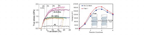
GRAPHICAL ABSTRACT
IMPACT STATEMENT
The flow stress of Al–Co alloys with high-density growth twins exceeds 1.5 GPa, while maintaining good work hardening capability. The twins are stabilized by Co impurities based on DFT calculations.
1. Introduction
High-strength, lightweight Aluminum (Al) alloys have raised significant attention due to their potential to improve fuel efficiency in the transportation industry. For instance, the high-strength 7XXX Al alloys are widely used in aircraft and automobile industry [Citation1]. However, the tensile strength of the best commercial Al alloys is ∼700 MPa [Citation2], which is less than that of the high-strength steels, 1–1.5 GPa [Citation3]. Conventionally, several major approaches, such as precipitation, work hardening, and solid solution hardening have been employed to strengthen Al alloys [Citation4]. Furthermore, grain refinement has been widely applied to strengthen Al alloys. For example, by using the cryomilling technique, the flow stress of nanocrystalline Al–Mg alloys with an average grain size of 26 nm reaches 750 MPa [Citation5]. Other severe plastic deformation techniques, such as equal channel angular pressing and high pressure torsion methods, have also been used to obtain high-strength, ultra-fine-grained Al alloys [Citation6]. While grain refinement is an effective approach to achieving high-strength in metallic materials, it often degrades the ductility due to the diminished work hardening ability [Citation7]. In comparison to high-energy grain boundaries (GBs), twin boundaries (TBs) can increase the flow stress, while maintaining ductility of metallic materials [Citation8]. In addition, nanotwinned metals have shown good thermal stability and electrical conductivity [Citation9].
Since the twin formability is closely related to the stacking fault energy (SFE) of a material, TBs are more stable in metals with low SFEs [Citation10]. Thus, most previous studies on nanotwinned metals focused on metallic materials with low-to-intermediate SFE. There are much fewer studies on the mechanical properties of twinned Al or Al alloys due to the high SFEs [Citation11]. Deformation twins have been spotted sporadically under high-strain-rate deformation [Citation12, Citation13] or in nanocrystals [Citation14, Citation15]. It is still a challenge to fabricate high-density twins in high SFE metals. A recent discovery on the twin formation ability of Al shows that specific texture can promote the formation of growth twins [Citation16]. Another approach to introduce twins in Al is to tune energy landscape by altering the alloy chemistry [Citation17]. The addition of Fe to Al matrix can promote the formation of twins, stacking faults and nanograins and thus significantly enhance the mechanical strength of Al alloys [Citation18]. However, it is unclear if the formation of high-density growth twins can also be accomplished in other Al alloys.
In this study, high-strength supersaturated Al–Co alloys were synthesized by using magnetron sputtering. The as-deposited films have nanograins containing abundant 9R phase. In situ uniaxial compression tests inside a scanning electron microscope show that certain Al–Co alloys have flow stresses of ∼1.5 GPa with considerable work hardening ability. Density function theory (DFT) calculations show that Co significantly improves the twin stability in Al. This study enriches our capability to accomplish the design of high-strength Al alloys by tailoring twin density and grain sizes.
2. Experimental details
Al and Al–Co alloy films were deposited by the magnetron sputtering technique on HF etched Si (111) substrates. Cross-section transmission electron microscopy (TEM) specimens and pillars were prepared by focus ion beam (FIB) instrument equipped in an FEI Quanta 3D FEG scanning electron microscope [Citation18, Citation19, Citation20]. The diameter and height of pillars are ∼500 and 1000 nm, respectively, and the taper angle is less than 2°. The microstructure of Al–Co specimens was examined using an FEI Talos 200X transmission electron microscope operated at 200 kV. In situ micropillar compression tests were conducted by using a Hysitron PI 88×R PicoIndenter with an average drift rate of 0.2 nm/s installed inside the FEI Quanta 3D FEG SEM microscope [Citation21, Citation22]. The force noise during the compression tests is below 5 µN and the displacement noise is less than 1 nm.
3. Results
A bright-field TEM image in Figure (a) shows fine columnar grains in the Al98.2-Co1.8 at.% (referred to as Al-1.8Co hereafter) film. The inserted selected area diffraction (SAD) pattern shows the (111) textured film with twin relation. A dark-field TEM image taken from the g vector shows curved columnar boundaries with
out-of-plane crystal orientation in Figure (b). A high-resolution TEM (HRTEM) micrograph shows several columnar nanograins containing 9R phase, which is a stacking fault ribbon consisting of 9 (111) planes as a repeating unit (Figure (c)). The arrows in Figure (c) indicate the locations of the broad 9R phase in columns 2 and 3, which are separated by low-angle GBs marked by dashed yellow lines. The Fast Fourier Transform (FFT) of area d in Figure (c) confirms the formation of the 9R phase. The magnified image of area d (Figure (d)) shows the discontinuity of the broad 9R phase decorated with the high-density defects.
Figure 1. The microstructure of as-deposited Al-1.8Co and Al-5.8Co films. (a, b, e, f) Bright-field and dark-field TEM micrographs showing the formation of columnar grains. The inserted selected area diffraction (SAD) pattern shows (111) texture with twins. (c) High-resolution TEM micrograph shows the formation of 9R phase in Al-1.8Co, and the inserted FFT shows the twinned structures at location d. The FFT of box A1 shows a single crystal diffraction pattern. (d) The magnified HRTEM micrograph showing the 9R phase in box d. (g) An HRTEM micrograph shows representative nanocolumns with high-density 9R phase in Al-1.8Co. (h) The magnified HRTEM micrograph and inserted FFT showing the 9R phase.
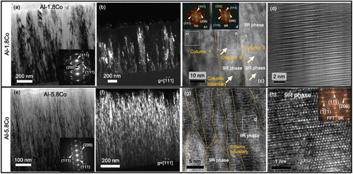
The as-deposited Al94.2-Co5.8 at.% (referred to as Al-5.8Co hereafter) film also has columnar nanograins as shown in cross-section TEM image in Figure (e). The XRD pole figures of Al-5.8Co film also show high-density twin structure in Fig. S2. A dark-field TEM image of the Al-5.8Co thin film (with g vector) in Figure (f) shows bright contrast of fine grains throughout the entire film. An HRTEM micrograph in Figure (g) displays fine columns with a high-density 9R phase. Regions with the 9R phase are shown in a magnified HRTEM micrograph in Figure (h) (as confirmed by the inserted FFT). The average grain size of Al-1.8 Co and Al-5.8Co is ∼23 and 5 nm, respectively (Fig. S3).
In situ uniaxial microcompression experiments have been performed on Al, Al-1.8Co, and Al-5.8Co pillars to compare their mechanical behaviors. Figure (a–c) compare the morphology of the pillars deformed to different strain levels. A ‘ductile' deformation of monolithic Al is observed in Figure (a1–a5), as evidenced by barreling of the pillar. Instead of barreling, the SEM micrographs of the deformed Al-1.8Co pillar show a conical shape geometry after the compression test. No catastrophic failure or cracks were observed up to a true strain of 50% (not shown here). Similar deformation geometry was observed in the Al-5.8Co pillars. The true stress–strain curve for the monolithic Al exhibits a low flow stress, ∼220 MPa (Figure (d)). In comparison, the flow stress reaches 950 MPa for Al-1.8 Co. The Al-5.8Co film has prominent strain hardening and a flow stress of 1600 MPa. The strain hardening rate of Al–Co alloys increases rapidly with the addition of Co solute as shown in Figure (e), and the strain hardening exponent of Al–Co alloys increases from ∼0.4 to ∼0.7, comparing to ∼0.2–0.3 for monolithic Al (Fig. S4).
Figure 2. In situ micropillar compression tests for single crystal Al and Al–Co films. (a–c) The SEM snap shots of Al (111) single crystal and Al-1.8Co and Al-5.8Co pillars captured during pillar compression tests. There is no detectable shear band or crack generation during deformation. (d) True stress–strain curves show that Al-1.8Co and Al-5.8 Co have a respective flow stress of ∼0.9 and 1.6 GPa, compared with pure Al, 0.23 GPa. (e) Comparisons of strain hardening effect among Al, Al-1.8Co, and Al-5.8Co samples.
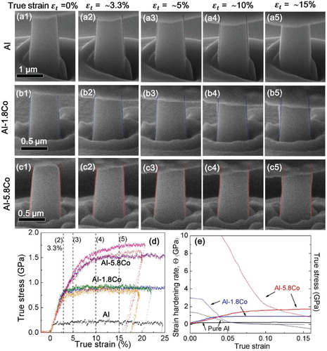
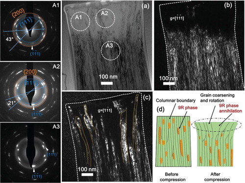
Figure shows the post-mortem TEM analyses of the Al-5.8Co pillar deformed to 15% true strain. Prominent dilation was observed in the top portion of the pillar as shown in the bright-field TEM image in Figure (a). The dark-field TEM image in Figure (b) collected using the g vector shows dark contrast for a significant portion of the deformed pillar top, indicating crystal reorientation during deformation. The diffraction patterns of several locations of the deformed pillar are shown in Figure (A1, A2, and A3). Different from a sharp diffraction spot, an arc shape spot indicates grain rotations during the pillar compression test. Comparisons of the diffraction patterns captured from location A1, A2, and A3 show that the top zone has severe crystal reorientations. More evidence of grain rotations is shown in Figs S5 and S6. Furthermore, the curved columnar grains and grain coarsening are evident as shown in Figure (c). A schematic in Figure (d) illustrates the deformation induced grain coarsening and rotation in the top portion of the deformed pillar.
Figure 3. Microstructure of Al-5.8Co pillar compresssed to 15% true strain. (a) The post-mortem BF TEM image showing the panoramic view of the deformed pillar. A1–A3 show the diffraction patterns taken from several locations in (a). (b, c) The post-mortem DF TEM images from and
diffraction spots. (d) The schematics showing the pillar morphology evolution after the compression test.
4. Discussions
In general, the formation of growth twins in Al is energetically unfavorable because of its high SFE. From a crystallography point of view, when Al grows epitaxially on Si (111) substrate, the two different nucleus variants have twinned orientation relation. Thus, instead of forming conventional high-energy GBs, ITB boundaries form when the nuclei impinge to minimize the interface energy. This growth-twin formation mechanism also applies to co-sputtered Al alloys grown epitaxially on Si (111) substrate. For instance, Zhang et al. [Citation23] observed high-density ITBs in sputtered Al–Ti thin films. Adding Co solute may drastically increase the energy barrier for the diffusion of Al atoms, resulting in fine columnar grains. Epitaxial growth along the <111> direction can promote the formation of growth twins. In addition to ITBs, the abundant 9R phase was also observed in Al–Co alloys. The formation of the 9R phase is not energetically favorable for Al, and even if the 9R phase can be formed, it is often not stable [Citation24]. Under projectile impact induced high-strain-rate deformation, the 9R phase has been observed in pure Al film during post-mortem TEM analysis [Citation12]. The formation of the 9R phase in Al–Co alloy warrants further discussions.
Even though the ITB and the 9R phase may form during deposition, the high SFE may trigger the instantaneous correction (detwinning) of faulted structures to minimize system energy [Citation25, Citation26]. To understand the formation of stable ITBs and the 9R phase in Al–Co alloy, DFT studies were carried out to calculate the energy profile, the generalized stacking fault energies, related to the detwinning and recovery of a faulted disk.
DFT calculations show that the formation energy of an individual substitutional Co atom is −0.847 eV, in comparison to 1.952 and 0.171 eV for the tetrahedral and octahedral interstitial site, respectively. Hence Co solute atoms prefer to occupy a substitutional lattice site. In order to understand the tendency of Co segregation, the formation energies of Co substitutional pairs are computed. For pairs of substitutional atoms that are located at the first, second, third, and fourth nearest positions, the respective formation energies per atom are −0.881, −0.838, −0.810, and −0.791 eV, suggesting that the closer the Co atoms, the lower their formation energy. But the formation energy of 4 nearest solute atoms (a cluster) is −0.628 eV per atom. This relatively high value means the segregation of Co solute atoms to form clusters is not thermodynamically preferred. However, we anticipate that Co impurity atoms may prefer to segregate to ITBs due to the lower defect formation energy. Recently, DFT calculations of defect formation energy for nanotwinned Ag–Fe solid solution alloy show that the Fe solute formation energy is lower along ITBs than in crystal lattices [Citation27]. In Al–Co thin films, there is no detectable Co segregation before and after micropillar compression tests (Fig. S7). Further studies are underway to calculate Co defect formation energy along ITBs and CTBs.
To understand the stability of SFs and tendency for detwinning during the film growth process, excess surface energies are calculated for surface trimers and heptamers, as shown in Figure (a) (details of calculations are provided in supplementary materials). The calculated excess energy per surface atom is plotted in Figure (b). The energy barrier for SF recovery by using a heptamer increases from 0.064 eV for pure Al to 0.101 eV with the addition of Co. Therefore, nanotwins and SFs formed during vapor deposition are preserved in as-deposited Al–Co films.
Figure 4. (a) Plan-view of (111) plane demonstrating the paths between stacking fault site and FCC site for heptamer and trimer cluster on the Al surface. (b) The excess energy per surface atom showing the energy barrier for the surface cluster (with and without solute atom) to move from FCC to stacking fault position. (c) Schematics of the solute atoms configurations on fault planes and the paths to annihilate the stacking faults. (d) Annihilation of an intrinsic stacking fault in Al with and without Co substitutional atom. The insertion is the atomistic configurations to calculate the generalized stacking fault energies of Aluminum with Co solute.
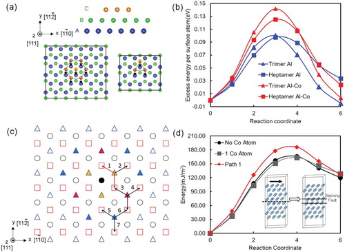
We also analyzed the influence of Co solute on the SFE of Al alloy by calculating the generalized SFE of Al and Al–Co. The calculated SFE of pure Al is 119.9 mJ/m2, which agrees with experimental measurements of SFEs, 120–144 mJ/m2 [Citation28]. Two solute atoms are placed on the two neighboring fault planes. We systematically analyzed the possibility of relative positions of two solutes before and after shearing the upper four layers to annihilate a SF. Among seven feasible paths (shown in Figure (c)) for the SF annihilation in Al-6 at.% Co, path 1 has the lowest formation energy, −0.552 eV/atom. Details of calculations are provided in supplementary materials. Hence we calculated the energy barrier of path 1. As shown in Figure (d), the red curve indicates that the energy barrier of annihilating a SF in Al–Co is ∼59 mJ/m2, which is greater than the energy barrier for removal of SF in pure Al, ∼46 mJ/m2. Thus, twins or SFs are stabilized once formed in sputtered Al–Co films.
The best high-strength commercial Al alloys have a flow stress of ∼700 MPa [Citation2]. In certain cases, Al-based metallic glasses containing transition metals and rare earth elements, or high percentage intermetallic particles, can obtain a high strength of ∼1 GPa [Citation29]. However, the poor ductility hinders the application of the Al-based metallic glasses. In comparison, the sputtered Al-5.8Co alloys exhibit high flow stress, >1.5 GPa, and substantial strain hardening ability during compression tests. Such high strength is comparable to the advanced high-strength steels. In what follows, the strengthening mechanisms of Al–Co alloys will be discussed.
The grain boundary strengthening induced by dislocation pile-ups can be described by the Hall–Petch relation as [Citation30, Citation31, Citation32], where
is the yield stress,
is the friction stress,
is the average domain size, and
is the Hall–Petch slope, which indicates the barrier strength of GBs for the transmission of dislocations [Citation33]. A broad range of
value for Al has been reported due to different microstructure or GB misorientation distributions [Citation34, Citation35]. The Hall–Petch plots of nanostructured Al and Al alloys with high-angle grain boundaries (HAGBs) and Σ3 (112) incoherent twin boundaries (ITBs) are shown in Fig. S9. The indistinguishable Hall–Petch slopes between HAGB and ITB indicate that, similar to HAGBs, the ITB is also a strong barrier for the transmission of dislocations. Furthermore, the flow stress of Al-1.8Co (d = 23 nm) deviates from the linear Hall–Petch relation. Softening was not observed even when d = 5 nm for nanotwinned Al-5.8Co films. Such an observation indicates that ITBs in nanotwinned Al alloys prevent softening. The rotation of grains in the top portion of the deformed pillars suggests that ITBs (columnar grain boundaries) migrated during deformation. ITB migration has been observed via in situ nanoindentation of nanotwinned Al [Citation36]. Furthermore, the migration of ITBs through mobile Shockley partials can also lead to grain coarsening. The capability of ITBs to migrate ensures that the high-strength nanotwinned Al alloys can deform under large shear stresses. ITBs in Al are less mobile comparing to conventional HAGBs as the SFE of Al is high, and DFT calculations in this study show that the addition of Co stabilizes ITBs and stacking faults.
In this study, high-density ITBs in the Al–Co alloys act as a strong barrier for dislocation transmission under uniaxial compression tests. The abundant 9R phase, a type of SF, may also contribute significantly to the high strength of the Al–Co alloys. Moreover, the work hardening exponent of Al-5.8Co is ∼0.7, which is much greater than that of conventional Al and Al alloys, ∼0.2–0.4 [Citation37]. MD simulations on Cu show that the migration of the 9R phase boundary contributes to the significant work hardening [Citation38]. The high flow stress was also observed recently in Al–Fe solid solution alloys with high-density TBs and the 9R phase. When adding ∼6 at.% Fe solute atoms into Al matrix, the flow stress of Al-Fe micropillars exceeds 1.5 GPa, and the hardness of the films reaches 5.6 GPa. MD simulations for Al-Fe alloys containing the 9R phase show that the 9R phase is a strong barrier to the transmission of dislocations, and facilitate the deformation at high stress via migration of partial dislocations, thus enabling outstanding deformability [Citation18].
5. Conclusions
Al–Co alloys with nanotwins and the 9R phase have been synthesized. In situ compression tests show that Al-5.8Co solid solution alloy has high flow stresses reaching 1.6 GPa with substantial strain hardening ability. Post-mortem microstructure analyses show the severe distortion at the pillar top in the form of grain coarsening, detwinning and rotation of columnar grains. DFT calculations show that the energy barrier for detwinning has been increased with the addition of Co. This study may shed light on the design of ultra-strong Al alloys with strength comparable to high-strength steels.
Supplemental_material_MRL.docx
Download MS Word (2.6 MB)Disclosure statement
No potential conflict of interest was reported by the authors.
ORCID
S. Xue http://orcid.org/0000-0002-8445-8718
Haiyan Wang http://orcid.org/0000-0002-7397-1209
J. Wang http://orcid.org/0000-0001-5130-300X
X. Zhang http://orcid.org/0000-0002-8380-8667
Additional information
Funding
Related Research Data
References
- Hirsch J. Recent development in aluminium for automotive applications. Trans Nonferr Met Soc China. 2014;24(7):1995–2002. doi: 10.1016/S1003-6326(14)63305-7
- Ma K, Wen H, Hu T, et al. Mechanical behavior and strengthening mechanisms in ultrafine grain precipitation-strengthened aluminum alloy. Acta Mater. 2014;62:141–155. doi: 10.1016/j.actamat.2013.09.042
- Kuziak R, Kawalla R, Waengler S. Advanced high strength steels for automotive industry. Arch Civil Mech Eng. 2008;8(2):103–117. doi: 10.1016/S1644-9665(12)60197-6
- Fine ME. Precipitation hardening of aluminum alloys. Metall Mater Trans A. 1975;6(4):625–630. doi: 10.1007/BF02672283
- Youssef K, Scattergood R, Murty K, et al. Nanocrystalline Al–Mg alloy with ultrahigh strength and good ductility. Scr Mater. 2006;54(2):251–256. doi: 10.1016/j.scriptamat.2005.09.028
- Liddicoat PV, Liao X-Z, Zhao Y, et al. Nanostructural hierarchy increases the strength of aluminium alloys. Nat Commun. 2010;1:1. doi: 10.1038/ncomms1062
- Hahn EN, Meyers MA. Grain-size dependent mechanical behavior of nanocrystalline metals. Mater Sci Eng A. 2015;646:101–134. doi: 10.1016/j.msea.2015.07.075
- Lu L, Chen X, Huang X, et al. Revealing the maximum strength in nanotwinned copper. Science. 2009;323(5914):607–610. doi: 10.1126/science.1167641
- Anderoglu O, Misra A, Wang H, et al. Thermal stability of sputtered Cu films with nanoscale growth twins. J Appl Phys. 2008;103(9):094322. doi: 10.1063/1.2913322
- Wang YM, Sansoz F, LaGrange T, et al. Defective twin boundaries in nanotwinned metals. Nat Mater. 2013;12(8):697–702. doi: 10.1038/nmat3646
- Velasco L, Hodge AM. Growth twins in high stacking fault energy metals: microstructure, texture and twinning. Mater Sci Eng A. 2017;687:93–98. doi: 10.1016/j.msea.2017.01.065
- Xue S, Fan Z, Lawal OB, et al. High-velocity projectile impact induced 9R phase in ultrafine-grained aluminium. Nat Commun. 2017;8(1):1653. doi: 10.1038/s41467-017-01729-4
- Zhao F, Wang L, Fan D, et al. Macrodeformation twins in single-crystal Aluminum. Phys. Rev. Lett.. 2016;116(7):075501. doi: 10.1103/PhysRevLett.116.075501
- Chen M, Ma E, Hemker KJ, et al. Deformation twinning in nanocrystalline aluminum. Science. 2003;300(5623):1275–1277. doi: 10.1126/science.1083727
- Liao X, Zhou F, Lavernia E, et al. Deformation twins in nanocrystalline Al. Appl Phys Lett. 2003;83(24):5062–5064. doi: 10.1063/1.1633975
- Xue S, Kuo W, Li Q, et al. Texture-directed twin formation propensity in Al with high stacking fault energy. Acta Mater. 2018;144:226–234. doi: 10.1016/j.actamat.2017.10.053
- Leyson GPM, Curtin WA, Hector Jr LG, et al. Quantitative prediction of solute strengthening in aluminium alloys. Nat Mater. 2010;9(9):750. doi: 10.1038/nmat2813
- Li Q, Xue S, Wang J, et al. High-strength nanotwinned Al Alloys with 9R phase. Adv Mater. 2018;30:1704629. doi: 10.1002/adma.201704629
- Ding J, Li Q, Li J, et al. Mechanical behavior of structurally gradient nickel alloy. Acta Mater. 2018;149:57–67. doi: 10.1016/j.actamat.2018.02.021
- Ng K, Ngan A. Stochastic nature of plasticity of aluminum micro-pillars. Acta Mater. 2008;56(8):1712–1720. doi: 10.1016/j.actamat.2007.12.016
- Frick C, Clark B, Orso S, et al. Size effect on strength and strain hardening of small-scale [111] nickel compression pillars. Mater Sci Eng A. 2008;489(1–2):319–329. doi: 10.1016/j.msea.2007.12.038
- Kunz A, Pathak S, Greer JR. Size effects in Al nanopillars: single crystalline vs. bicrystalline. Acta Mater. 2011;59(11):4416–4424. doi: 10.1016/j.actamat.2011.03.065
- Zhang YF, Xue S, Li Q, et al. Microstructure and mechanical behavior of nanotwinned AlTi alloys with 9R phase. Scr Mater. 2018;148:5–9. doi: 10.1016/j.scriptamat.2018.01.010
- Wang J, Misra A, Hirth J. Shear response of Σ 3 {112} twin boundaries in face-centered-cubic metals. Phys Rev B. 2011;83(6):064106. doi: 10.1103/PhysRevB.83.064106
- Li B, Sui M, Li B, et al. Reversible twinning in pure aluminum. Phys. Rev. Lett.. 2009;102(20):205504. doi: 10.1103/PhysRevLett.102.205504
- Yamakov V, Wolf D, Salazar M, et al. Length-scale effects in the nucleation of extended dislocations in nanocrystalline Al by molecular-dynamics simulation. Acta Mater. 2001;49(14):2713–2722. doi: 10.1016/S1359-6454(01)00167-7
- Li J, Xie D, Xue S, et al. Superior twin stability and radiation resistance of nanotwinned Ag solid solution alloy. Acta Mater. 2018;151:395–405. doi: 10.1016/j.actamat.2018.03.052
- Rautioaho R. An interatomic pair potential for aluminium calculation of stacking fault energy. Phys Status Solidi B. 1982;112(1):83–89. doi: 10.1002/pssb.2221120108
- Wang Z, Qu RT, Scudino S, et al. Hybrid nanostructured aluminum alloy with super-high strength. NPG Asia Mater. 2015;7(12):e229. doi: 10.1038/am.2015.129
- Hall E. The deformation and ageing of mild steel: III discussion of results. Proc Phys Soc Sect B. 1951;64(9):747–753. doi: 10.1088/0370-1301/64/9/303
- Petch N. The cleavage strength of polycrystals. J Iron Steel Inst. 1953;174:25–28.
- Cordero Z, Knight B, Schuh C. Six decades of the Hall–Petch effect – a survey of grain-size strengthening studies on pure metals. Int Mater Rev. 2016;61(8):495–512. doi: 10.1080/09506608.2016.1191808
- Misra A, Hirth J, Hoagland R. Length-scale-dependent deformation mechanisms in incoherent metallic multilayered composites. Acta Mater. 2005;53(18):4817–4824. doi: 10.1016/j.actamat.2005.06.025
- Hansen N. Hall–Petch relation and boundary strengthening. Scripta Mater. 2004;51(8):801–806. doi: 10.1016/j.scriptamat.2004.06.002
- Wyrzykowski J, Grabski M. The Hall–Petch relation in aluminium and its dependence on the grain boundary structure. Philos Mag A. 1986;53(4):505–520. doi: 10.1080/01418618608242849
- Bufford D, Liu Y, Wang J, et al. In situ nanoindentation study on plasticity and work hardening in aluminium with incoherent twin boundaries [Article]. Nat Commun. 2014;5. doi:10.1038/ncomms5864.
- Callister WD. Materials science and engineering: An introduction. Chichester: Wiley; 1985; 602 pp.
- Yu W, Shen S, Liu Y, et al. Nonhysteretic superelasticity and strain hardening in a copper bicrystal with a∑ 3 {112} twin boundary. Acta Mater. 2017;124:30–36. doi: 10.1016/j.actamat.2016.10.062