
ABSTRACT
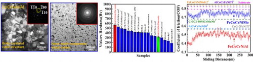
The high-entropy alloy coatings reinforced with nano oxides were synthesized by the atmospheric plasma spraying (APS). The crystal structure, microstructure, surface morphology, hardness and wear resistance properties of the CoCrFeNiAl and CoCrFeNiMo high-entropy alloy coatings are investigated. For CoCrFeNiAl high entropy coating (HEC) not only has high hardness (573 ± 19 Hv0.1) but also has good wear resistance [The coefficients of friction (COF) is 0.49 ± 0.04]. The transition of the wear mechanism obviously appears between the two HECs. The influences of the structure, composition and hardness on the tribological behavior of high-entropy alloy coatings were discussed in details.
GRAPHICAL ABSTRACT
IMPACT STATEMENT
Nano oxides enhanced high-entropy coatings (HECs) are successfully fabricated by atmospheric plasma spraying, which exhibit the highest hardness and the best wear resistance in HECs and high-entropy alloys.
High-entropy alloys (HEAs), containing five or more multiple principal metallic elements with an equal or near-equal atomic percentage, are intensively studied in the past ten years [Citation1–5]. High configurational entropy, sluggish diffusion, the cocktail effect and lattice distortions constitute the four main features of HEAs [Citation1,Citation2]. Due to these features, HEAs usually possess outstanding performances, such as the high hardness and strength, good corrosion resistance, high fatigue resistance, excellent wear resistance and thermal stability [Citation6–11]. As such, HEAs are good materials for coatings, based on which high-entropy coatings (HECs) are developed recently. Previous studies have found that HECs possess the excellent performances that are even higher than those of HEAs [Citation12,Citation13], indicating that HECs have a wide range of potential applications [Citation12–16].
HECs can be fabricated by various techniques [Citation13], including magnetron sputtering [Citation17,Citation18], laser cladding [Citation14,Citation19], spraying [Citation15,Citation20], electrodeposition [Citation21,Citation22], etc. However, little attention has been paid to the preparation of HECs by thermal spraying. As one of the most widely-used thermal-spraying technique, atmospheric-plasma spraying (APS) is a potential processing route for fabricating HECs due to its simple manufacturing process, wide range of powder selection, and high production efficiency. Therefore, in the present work, two different single-phase solid-solution HEA coatings, i.e. CoCrFeNiAl and CoCrFeNiMo HEAs, doped with nano-multi-component metal oxides were synthesized by the atmospheric plasma spraying (APS). The high hardness and excellent wear resistance performance of the HECs are achieved. The detailed information about the experimental procedure and results are provided in the Supplementary materials.
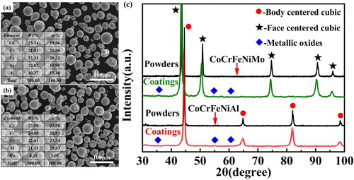
Figure (a and b) show the profiles of CoCrFeNiAl and CoCrFeNiMo feedstock powders, respectively. The powders have spherical or near-spherical shapes, and the sizes of powders range from 30 to 50 µm. The size distributions of two feedstock powders are presented in Figure S1, which show near-Gaussian distributions. The XRD spectrum for feedstock powders and coatings are displayed in Figure (c). The CoCrFeNiAl HEA powder exhibits a body-centered-cubic (BCC) single-phase structure. The CoCrFeNiMo HEA powder has a face-centered-cubic (FCC) single-phase structure. After spraying, the XRD patterns indicate that the main phase structures do not significantly change, i.e. the BCC structure still occupies the CoCrFeNiAl HEC, and the FCC structure occupies the CoCrFeNiMo HEC. Besides the main phase, a small quantity of unindexed phases is found. The unindexed phases are possibly the complex metallic oxide that are formed during the APS process.
Figure 1. SEM morphologies and EDS results of (a) CoCrFeNiAl powders, (b) CoCrFeNiMo powders; (c) XRD spectrums for CoCrFeNiAl and CoCrFeNiMo powders and coatings.
The morphologies and the elemental distributions of the CoCrFeNiAl and CoCrFeNiMo HECs are shown in Figure . The surfaces of coatings are rough, which are the inherent characteristics of coatings by APS [Citation23]. Generally, during the APS process, the heat input of the plasma jet on the flying-powder particles is not homogeneous. When the feedstock powders with a wide particle-size range are injected into the plasma jet, different kinetics and thermal energies are obtained by the particles, which can cause the particles to be in various states, including fully-molten, semi-molten, and unmelted particles [Citation24]. The fully-molten particles with an enough velocity can form the well-flattened splats when they strike the substrate, which have been marked in Figure (a and g). For the semi-molten particles, they are rebounded on the coatings, which exhibit some rough bulges, as marked in Figure (a and g). However, the surface of the CoCrFeNiMo HEC exhibits that some unmelted particles are bonded on the surface of the coating [Figure (g)], which cannot be observed in the CoCrFeNiAl HEC [Figure (a)]. Figure (b and h) provide the three-dimensional (3D) surface morphologies of the CoCrFeNiAl and CoCrFeNiMo HECs, which present many bulges appearing on the surface of the CoCrFeNiMo HEC. The surface of the CoCrFeNiAl HEC is flatter than that of the CoCrFeNiMo HEC. Based on Figure (b) and (h), the surface-roughness values, Ra, of the HECs are measured to be 11.9 ± 0.5 µm for the CoCrFeNiAl HEC, and 14.6 ± 0.7 µm for the CoCrFeNiMo HEC, respectively, which further confirms that the CoCrFeNiAl HEC is smoother than that of the CoCrFeNiMo HEC quantitatively. The thicknesses of the HECs are approximately 310 ± 35 µm for the CoCrFeNiAl HEC and 255 ± 25 µm for the CoCrFeNiMo HEC, respectively [Figure (c and i)]. The difference in the thicknesses of two HECs indicates that the deposition efficiency of the CoCrFeNiAl HEC is significantly higher than that of the CoCrFeNiMo HEC fabricated with the same APS parameters. The aluminum element of the CoCrFeNiAl HEA is replaced by molybdenum, which significantly improves the melting point of the CoCrFeNiMo HEA powders. In this case, some of the CoCrFeNiMo HEA powders are not fully melted, which leads to the low deposition efficiency. After polishing the cross sections of HECs, the SEM images show some dark and bright regions [Figure (d and j)]. Further energy-dispersive spectrometry (EDS) analyzing the elemental distributions in the dark and bright regions indicates that the dark regions are the oxide banded structure because the oxygen content in the dark region approaches about 50 at. %, and the oxide banded structure is mainly composed of a variety of complex metal oxides (Table ). The elemental distribution in the bright region matches well with the HEA solid solution (5 ∼ 35 at. %) (Table ). Figure (e and k) exhibit the polished surfaces of the CoCrFeNiAl and CoCrFeNiMo HECs, which are composed of a great number of metal oxides and HEA matrix with some cavities embedded into the surface of coatings. The cavity formation is due to the loose adhesion between the spraying layers, and gas escaping from coatings [Citation23,Citation24]. It is obvious that a large number of layered wrapping structures exist on the polished surface of the two coatings. The layered wrapping structure consists of dark banded region of multi-component metal oxides and bright region of HEA matrix. The local regions covered by blue rectangles in Figure (e and k) are enlarged, as shown in Figure (f and l) that are further characterized by the electron probe micro analysis (EPMA). It is obvious that the compositions in the HEA solid solutions are homogeneously distributed, and an enrichment of metal oxides is in the oxide of layered wrapping structure. The EPMA result of the area in Figure (f) and Table indicate that the aluminum element is mainly enriched in the dark region, and the average content is 37.7 at. % in the CoCrFeNiAl HEC (Table ). The EPMA result of the area in Figure (l) and Table indicate that the chromium element is mainly enriched in the dark region, and its atomic percent is 34.4% in the CoCrFeNiMo HEC (Table ). Therefore, the dark region in the CoCrFeNiAl HEC is mostly the alumina oxide, and that in the CoCrFeNiMo HEC is generally the chromium oxide. The XPS analysis indicates that the CoCrFeNiAl HEC mainly contains Co3O4, Cr2O3, Fe2O3, Fe3O4, NiO, and Al2O3, and the CoCrFeNiMo HEC generally contains Co3O4, Cr2O3, Fe2O3, Fe3O4, NiO and a small amount of MoOx (Please see the Supplementary Materials, Figure S2). Accordingly, both HECs are composed of the HEA matrix and multi-component metal oxides.
Figure 2. The original surface, three-dimensional surface, vertical sectional, cross-sectional morphologies, and the elemental-distribution maps by EPMA for CoCrFeNiAl (a - f) and CoCrFeNiMo (g - l) HECs.
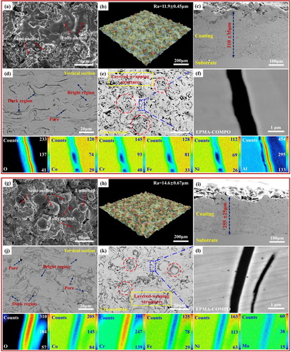
Table 1. Theoretical and actual powder compositions and average compositions (at. %) in dark and bright regions of the CoCrFeNiAl and CoCrFeNiMo HECs.
The TEM analysis can further characterize the microstructures of the HEA matrix and multi-component metal oxides in the HECs. Figure (a and d) present the bright-field images of the HEA matrix and nano-multi-component metal oxides for the CoCrFeNiAl and CoCrFeNiMo HECs, respectively. Figure (b and e) show the morphologies of the HEA matrix for the CoCrFeNiAl and CoCrFeNiMo HECs, respectively. It can be clearly seen that the phase of the matrix for the CoCrFeNiAl HEC is determined to be a solid-solution with a BCC structure, and the grain size is about 200 ∼ 500 nm [Figure (b)]. For the CoCrFeNiMo HEC, the phase structure of the matrix is FCC solid-solution, and the gain size is almost the same as the value in the CoCrFeNiAl HEC. The bright-field image and the selected-area electron diffraction CoCrFeNiAl HEC) and 49 ± 12 nm (for the CoCrFeNiMo HEC) are clearly observed in Figure (c and f). The polycrystalline diffraction rings are observed in the (SAED) patterns of multi-component metal oxides for the CoCrFeNiAl and CoCrFeNiMo HECs are shown in Figure (c and f), respectively. From this, numerous nano-grains with the average grain diameter of 38 ± 8 nm (for the CoCrFeNiAl and CoCrFeNiMo HECs, which point to the phases of nano-multi-component metal oxides, as exhibited in Figure (c and f), respectively.
Figure 3. TEM micrographs of the microstructure of the HECs: (a) BF image; (b) BF image and SAED patterns of the HEA matrix; (c) BF image and SAED ring pattern of nano-multi-component metal oxides for the CoCrFeNiAl HECs; (d) BF image, (e) BF image and SAED patterns of the HEA matrix; (f) BF image and SAED ring pattern of nano-multi-component metal oxides for the CoCrFeNiMo HECs.
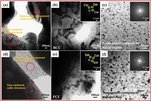
Figure (a and b) present the indentations of the Vickers hardness for the CoCrFeNiAl and CoCrFeNiMo HEC, respectively. To exclude the experimental error, the hardness tests were repeated ten times for each HEC. The average Vickers hardness (an HV diamond Indenter with a rectangular pyramid) values of two HECs are shown in Figure (c), which are 573 ± 19 and 319 ± 10 Hv0.1 for the CoCrFeNiAl and CoCrFeNiMo HEC, respectively. For a comparison, the hardness values of other HEAs, HECs, steels and titanium alloy with different compositions are also listed in Figure (c), in which the hardness of the CoCrFeNiAl HEC is significantly higher than those of other coatings and alloys, even higher than the value of the CoCrFeNiMo HEC.
Figure 4. The indentation of the Vickers hardness of (a) CoCrFeNiAl HEC; (b) CoCrFeNiMo HEC; (c) The Vickers hardness for CoCrFeNiAl and CoCrFeNiMo HECs by APS and other coatings by thermal spraying or alloys by casting (Hastelly C-Ni2.15Cr2.5Co13.5Mo4W5.5Fe1Mn; Stellite 6-Co29Cr4.5W1.2C wt.%) [Citation25–29].
![Figure 4. The indentation of the Vickers hardness of (a) CoCrFeNiAl HEC; (b) CoCrFeNiMo HEC; (c) The Vickers hardness for CoCrFeNiAl and CoCrFeNiMo HECs by APS and other coatings by thermal spraying or alloys by casting (Hastelly C-Ni2.15Cr2.5Co13.5Mo4W5.5Fe1Mn; Stellite 6-Co29Cr4.5W1.2C wt.%) [Citation25–29].](/cms/asset/c109f109-9c77-44b0-a56f-d23d9a84a2bb/tmrl_a_1604443_f0004_oc.jpg)
Figure (a) shows the coefficients of friction (COF) for the CoCrFeNiAl and CoCrFeNiMo HECs as the functions of the sliding distance. A small COF means a high wear resistance because it requires more energy to remove the same volume of the material [Citation30]. The COFs of the CoCrFeNiAl and CoCrFeNiMo HECs are 0.49 ± 0.04 and 0.75 ± 0.02, respectively [Figure (a)]. For a comparison, the COF of the FeCoCrNiMo0.2, AlCoCrFeNiTi, AlCoCrFeNiSi, CoCr2FeNiTi HECs, and Cr3C2-50NiCrMoNb coating are also marked by dash lines in Figure (a). It can be clearly seen that the CoCrFeNiAl HEC exhibits the best wear resistance. Figure (b–g) show the SEM images of the wear traces of the CoCrFeNiAl and CoCrFeNiMo HECs. From Figure (b and e), the wear trace widths of the CoCrFeNiAl and CoCrFeNiMo HECs are measured to be 1.36 ± 0.04 and 2.08 ± 0.07 mm, respectively. For the CoCrFeNiAl HEC, three characteristic areas, i.e. the groove, debris, and delamination are observed in the wear trace [Figure (c and d)]. However, for the CoCrFeNiMo HEC, the groove, debris, and flaky debris are observed [Figure (f and g)]. The chemical compositions of the wear traces for both coatings of different regions are listed in Table . In the CoCrFeNiAl HEC, the average composition distribution in the grooves is almost same as that of the CoCrFeNiAl HEA matrix with no oxygen. The other two areas show obviously oxidation, in which the atomic ratios of metallic elements are still near equal (Table ). The oxygen contents in the three regions for the CoCrFeNiMo HEC are all very high (13.12 ∼ 20.27 at. %). Some oxides, such as iron oxides, appear in the three regions, which indicates that the oxidative wear is one of its wear mechanisms in the CoCrFeNiMo HEC. Accordingly, the wear mechanisms must include the mild oxidative wear. At the end of friction, abrasive grooves were clearly observed in the wear trace of the CoCrFeNiMo HEC. For the CoCrFeNiAl HEC, a smooth wear trace with a few of shallowly-abrasive grooves is observed [Figure (b)]. The wear debris in the CoCrFeNiAl HEC is a particle-like shape and finer (around 5 ∼ 20 µm) than that of the CoCrFeNiMo HEC [Figure (c and f)]. For the CoCrFeNiMo HEC, the flakes are a platelet-like shape. The large debris accumulates on the worn surface with the increasing of the COF. These results illustrate that more adhesive and abrasive wear features took place in the CoCrFeNiMo HEC, as compared with that in the CoCrFeNiAl HEC. According to the theory of the adhesive wear, the adhesive material can slide between the surfaces of the friction pairs during the subsequent sliding process. Thus, if the friction continues, the partially-transferred materials will fall off the surface due to work hardening, oxidation, or other reasons, resulting in the loss material from the surface [Citation31]. The wear rate of the CoCrFeNiAl HEC was less than those of the CoCrFeNiMo HEC and the substrate [Figure S3]. The CoCrFeNiMo HEC suffered the severe adhesive wear, which is evidenced by the intensively-plastic flow and plowing grooves with a high stress [Figure (f and g)] [Citation30,Citation32–36]. The materials loss in the CoCrFeNiMo HEC seems to occur primarily by ploughing with the wedge formation due to the intensively-plastic deformation induced by the hard rubbing-pair, in particular by the oxide particles generated during the wear process itself [Citation37].
Figure 5. (a) The COFs for CoCrFeNiAl and CoCrFeNiMo HECs by APS and other coatings by thermal spraying [Citation38–41]; The SEM micrographs of the wear traces of (b)-CoCrFeNiAl; (c, d)-higher magnification for CoCrFeNiAl HECs; (e)-CoCrFeNiMo; (f, g)-higher magnification for CoCrFeNiMo HECs.
![Figure 5. (a) The COFs for CoCrFeNiAl and CoCrFeNiMo HECs by APS and other coatings by thermal spraying [Citation38–41]; The SEM micrographs of the wear traces of (b)-CoCrFeNiAl; (c, d)-higher magnification for CoCrFeNiAl HECs; (e)-CoCrFeNiMo; (f, g)-higher magnification for CoCrFeNiMo HECs.](/cms/asset/def60d86-dc42-4540-887f-759b8ef52bfa/tmrl_a_1604443_f0005_oc.jpg)
Table 2. Average compositions (at. %) distributions of CoCrFeNiAl and CoCrFeNiMo HECs after the friction and wear tests.
The results of the present study demonstrate that both HECs are composed of the single-phase solid-solution HEA matrix and nano-multi-component metal oxides. Usually, the hardness of the BCC HEA is obviously higher than that of the FCC HEA [Citation30]. High hardness is one of the prerequisites for the HEA with excellent wear resistance. Besides the properties of the HEA matrix, the layered wrapping structure in the coating is of importance for its wear performance [Citation42]. On the wear trace of the CoCrFeNiAl HEC, the atomic ratios of the metallic elements in the wear debris are still near equal. During the wear process, the nano-multi-component metal oxides flake off, and freely distribute on the surface of the coating, which thus effectively stop the occurrence of the severe adhesion wear. The friction-reducing effect due to a denudation of nano-multi-component metal oxides, and the formation of the micron-size particle-like debris on the surface of the coatings can effectively lubricate the friction process between the CoCrFeNiAl HEC surface and the rubbing-pair (Si3N4) [Citation16,Citation42–44]. Therefore, the CoCrFeNiAl HEC containing nano-multi-component metal oxides exhibits high hardness and good wear resistance.
Disclosure statement
No potential conflict of interest was reported by the authors.
Additional information
Funding
References
- Tsai MH, Yeh JW. High-entropy alloys: A critical review. Mater Res Lett. 2014;2:107–123. doi: 10.1080/21663831.2014.912690
- Zhang Y, Zuo TT, Tang Z, et al. Microstructures and properties of high-entropy alloys. Prog Mater Sci. 2014;61:1–93. doi: 10.1016/j.pmatsci.2013.10.001
- Miracle DB, Senkov ON. A critical review of high entropy alloys and related concepts. Acta Mater. 2017;122:448–511. doi: 10.1016/j.actamat.2016.08.081
- Yang T, Zhao YL, Tong Y, et al. Multicomponent intermetallic nanoparticles and superb mechanical behaviors of complex alloys. Science. 2018;362:933–937. doi: 10.1126/science.aas8815
- Lei ZF, Liu XJ, Wu Y, et al. Enhanced strength and ductility in a high-entropy alloy via ordered oxygen complexes. Nature. 2018;563:546–550. doi: 10.1038/s41586-018-0685-y
- Yang T, Zhao YL, Liu WH, et al. Ductilizing brittle high-entropy alloys via tailoring valence electron concentrations of precipitates by controlled elemental partitioning. Mater Res Lett. 2018;6:600–606. doi: 10.1080/21663831.2018.1518276
- Wu SW, Wang G, Wang Q, et al. Enhancement of strength-ductility trade-off in a high-entropy alloy through a heterogeneous structure. Acta Mater. 2019;165:444–458. doi: 10.1016/j.actamat.2018.12.012
- Shi YZ, Collins L, Feng R, et al. Homogenization of AlxCoCrFeNi high-entropy alloys with improved corrosion resistance. Corros Sci. 2018;133:120–131. doi: 10.1016/j.corsci.2018.01.030
- Joseph J, Haghdadi N, Shamlaye K, et al. The sliding wear behaviour of CoCrFeMnNi and AlxCoCrFeNi high entropy alloys at elevated temperatures. Wear. 2019;428-429:32–44. doi: 10.1016/j.wear.2019.03.002
- Tang Z, Yuan T, Tsai CW, et al. Fatigue behavior of a wrought Al0.5CoCrCuFeNi two-phase high-entropy alloy. Acta Mater. 2015;99:247–258. doi: 10.1016/j.actamat.2015.07.004
- Zou Y, Ma H, Spolenak R. Ultrastrong ductile and stable high-entropy alloys at small scales. Nat Commun. 2015;6:7748. doi: 10.1038/ncomms8748
- Yan XH, Li JS, Zhang WR, et al. A brief review of high-entropy films. Mater Chem Phys. 2018;210:12–19. doi: 10.1016/j.matchemphys.2017.07.078
- Li W, Liu P, Liaw PK. Microstructures and properties of high-entropy alloy films and coatings: a review. Mater Res Lett. 2018;6:199–229. doi: 10.1080/21663831.2018.1434248
- Qiu XW. Microstructure, hardness and corrosion resistance of Al2CoCrCuFeNiTix high-entropy alloy coatings prepared by rapid solidification. J Alloys Compd. 2018;735:359–364. doi: 10.1016/j.jallcom.2017.11.158
- Chen LJ, Bobzin K, Zhou Z, et al. Wear behavior of HVOF-sprayed Al0.6TiCrFeCoNi high entropy alloy coatings at different temperatures. Surf Coat Tech. 2019;358:215–222. doi: 10.1016/j.surfcoat.2018.11.052
- Jin G, Cai ZB, Guan YJ, et al. High temperature wear performance of laser-cladded FeNiCoAlCu high-entropy alloy coating. Appl Surf Sci. 2018;445:113–122. doi: 10.1016/j.apsusc.2018.03.135
- Braeckman BR, Boydens F, Hidalgo H, et al. High entropy alloy thin films deposited by magnetron sputtering of powder targets. Thin Solid Films. 2015;580:71–76. doi: 10.1016/j.tsf.2015.02.070
- Liao WB, Zhang H, Liu ZY, et al. High strength and deformation mechanisms of Al0.3CoCrFeNi high-entropy alloy Thin Films fabricated by magnetron sputtering. Entropy. 2019;21:146. doi: 10.3390/e21020146
- Jiang H, Han K, Li D, et al. Synthesis and Characterization of AlCoCrFeNiNbx high-entropy alloy coatings by laser cladding. Crystals (Basel). 2019;9:56. doi: 10.3390/cryst9010056
- Hsu WL, Yang YC, Chen CY, et al. Thermal sprayed high-entropy NiCo0.6Fe0.2Cr1.5SiAlTi0.2 coating with improved mechanical properties and oxidation resistance. Intermetallics. 2017;89:105–110. doi: 10.1016/j.intermet.2017.05.015
- Wang B, Huang J, Fan JH, et al. Preparation of FeCoNiCrMn high entropy alloy by electrochemical reduction of solid oxides in molten salt and its corrosion behavior in aqueous solution. J Electrochem Soc. 2017;164:E575–E579. doi: 10.1149/2.1521714jes
- Yao CZ, Zhang P, Liu M, et al. Electrochemical preparation and magnetic study of BiFeCoNiMn high entropy alloy. Electrochim Acta. 2008;53:8359–8365. doi: 10.1016/j.electacta.2008.06.036
- Fauchais PL, Heberlein JVR, Boulos ML. Thermal spray fundamentals. New York: Springer Science + Business Media; 2014.
- Juraj R, Anton P. Plasma and thermal spraying. This springer imprint is published by Springer Nature, the registered company address is: Gewerbestrasse 11, 6330 Cham, Switzerland;2017.
- Hari PS, Cijo M, Jacob K, et al. Comparative study of high entropy alloys AlCoCrFeNi, AlCoFeNi and CoCrFeNi with 304SS. Int J Eng Inno Tech. 2016;6:29–33.
- Chen QS, Dong Y, Zhang JJ, et al. Microstructure and properties of AlCoCrFeNiBx (x = 0, 0.1, 0.25, 0.5, 0.75, 1.0) high entropy alloys. Rare Metal Mater Eng. 2017;46:651–656. doi: 10.1016/S1875-5372(17)30112-1
- Senkov ON, Senkova SV, Woodward C, et al. Low-density, refractory multi-principal element alloys of the Cr-Nb-Ti-V-Zr system: microstructure and phase analysis. Acta Mater. 2013;61:1545–1557. doi: 10.1016/j.actamat.2012.11.032
- Wang WR, Wang WL, Yeh JW. Phases, microstructure and mechanical properties of AlxCoCrFeNi high-entropy alloys at elevated temperatures. J Alloys Compd. 2014;589:143–152. doi: 10.1016/j.jallcom.2013.11.084
- Ang ASM, Berndt CC, Sesso ML, et al. Plasma-Sprayed high entropy alloys: microstructure and properties of AlCoCrFeNi and MnCoCrFeNi. Metallurgical and Materials Transactions A. 2014;46:791–800. doi: 10.1007/s11661-014-2644-z
- Wu JM, Lin SJ, Yeh JW, et al. Adhesive wear behavior of AlxCoCrCuFeNi high-entropy alloys as a function of aluminum content. Wear. 2006;261:513–519. doi: 10.1016/j.wear.2005.12.008
- Hutchings I, Shipway P. Tribology. Oxford: Published by Elsevier Ltd; 2017.
- Tian LH, Feng ZK, Xiong W. Microstructure, Microhardness, and wear resistance of AlCoCrFeNiTi/Ni60 coating by plasma spraying. Coatings. 2018;8:112. doi: 10.3390/coatings8030112
- Tian LH, Xiong W, Liu C, et al. Microstructure and wear behavior of atmospheric plasma-Sprayed AlCoCrFeNiTi high-entropy alloy coating. J Mater Eng Perform. 2016;25:5513–5521. doi: 10.1007/s11665-016-2396-6
- Wang YX, Yang YJ, Yang HJ, et al. Microstructure and wear properties of nitrided AlCoCrFeNi high-entropy alloy. Mater Chem Phys. 2018;210:233–239. doi: 10.1016/j.matchemphys.2017.05.029
- Zhou R, Chen G, Liu B, et al. Microstructures and wear behaviour of (FeCoCrNi)1–x(WC)x high entropy alloy composites. Int J Refract Met H. 2018;75:56–62. doi: 10.1016/j.ijrmhm.2018.03.019
- Koga GY, Wolf W, Schulz R, et al. Corrosion and wear properties of FeCrMnCoSi HVOF coatings. Surf Coat Tech. 2019;357:993–1003. doi: 10.1016/j.surfcoat.2018.10.101
- Huang C, Zhang YZ, Vilar R, et al. Dry sliding wear behavior of laser clad TiVCrAlSi high entropy alloy coatings on Ti-6Al-4 V substrate. Mater Design. 2012;41:338–343. doi: 10.1016/j.matdes.2012.04.049
- Li T, Liu Y, Liu B, et al. Microstructure and wear behavior of FeCoCrNiMo0.2 high entropy coatings prepared by air plasma spray and the high velocity oxy-fuel spray processes. Coatings. 2017;7:151–164. doi: 10.3390/coatings7090151
- Matikainen V, Bolelli G, Koivuluoto H, et al. Sliding wear behaviour of HVOF and HVAF sprayed Cr3C2-based coatings. Wear. 2017;388-389:57–71. doi: 10.1016/j.wear.2017.04.001
- Tian LH, Fu M, Xiong W. Microstructural evolution of AlCoCrFeNiSi high-entropy alloy powder during mechanical alloying and its coating performance. Materials (Basel). 2018;11:1–18.
- Guo Y, Shang X, Liu Q. Microstructure and properties of in-situ TiN reinforced laser cladding CoCr2FeNiTix high-entropy alloy composite coatings. Surf Coat Tech. 2018;344:353–358. doi: 10.1016/j.surfcoat.2018.03.035
- Huang CJ, Yan XC, Li WY, et al. Post-spray modification of cold-sprayed Ni-Ti coatings by high-temperature vacuum annealing and friction stir processing. Appl Surf Sci. 2018;451:56–66. doi: 10.1016/j.apsusc.2018.04.257
- Xiang ZF, Liu XB, Ren J, et al. Investigation of laser cladding high temperature anti-wear composite coatings on Ti6Al4 V alloy with the addition of self-lubricant CaF2. Appl Surf Sci. 2014;313:243–250. doi: 10.1016/j.apsusc.2014.05.196
- Zhang C, Liu L, Chan KC, et al. Wear behavior of HVOF-sprayed Fe-based amorphous coatings. Intermetallics. 2012;29:80–85. doi: 10.1016/j.intermet.2012.05.004