
 ?Mathematical formulae have been encoded as MathML and are displayed in this HTML version using MathJax in order to improve their display. Uncheck the box to turn MathJax off. This feature requires Javascript. Click on a formula to zoom.
ABSTRACT
There has been a long-standing controversy on how dislocations interact with interfaces. Here we report in-situ observations that in a Cu–brass heterostructured TEM film Frank–Read sources are the primary dislocation sources. They were dynamically formed and deactivated throughout the deformation in grain interior, which has never been reported before. This observation indicates that strain gradient near interfaces cannot be quantitatively related to the density gradient of geometrically necessary dislocations, and it was primarily produced by Frank–Read source gradient instead of dislocation pile-ups. These findings provide new insights on how to design heterostructured interfaces to enhance mechanical properties.
GRAPHICAL ABSTRACT
It has been a perpetual challenge to produce strong and tough materials for engineering applications. Many approaches have been reported to produce strong materials, but these often come at the sacrifice of ductility [Citation1–3]. Good ductility is required for a strong material to be simultaneously tough. Interface engineering such as introducing twins [Citation4,Citation5], second-phases [Citation6,Citation7], and grain refinement [Citation1] have been extensively reported for improving the strength and/or ductility of metals. Their general principle is to utilize dislocation–interface interactions to modify mechanical behavior.
Recently, heterostructured (HS) materials were found to be able to avoid the trade-off between strength and ductility [Citation3,Citation8]. This makes it essential to understand how dislocations interact with HS interfaces so as to pave the scientific foundation for this new type of materials. The superior mechanical properties were attributed to back-stress-induced synergistic strengthening and work hardening, which are produced by the piling-up of geometrically necessary dislocations (GNDs) at HS domain interfaces [Citation8]. Electron backscatter diffraction (EBSD) indeed revealed GND gradient near interfaces in a Cu–brass heterostructure after tensile testing, which seems to agree with the popular dislocation pile-up theory [Citation9–12]. However, a negative strain gradient was recently found near the Cu–brass interface, i.e. the higher plastic strain the nearer the interface [Citation13]. This is contrary to the strain gradient produced by GND pileup from Frank–Read sources. Therefore, it was concluded that the strain gradient was produced by dislocation emissions from the interface [Citation13], which is consistent with a minority view that the Frank–Read sources rarely exist in grain interior and interfaces such as grain boundaries are the primary dislocation sources [Citation14–16]. This minority view has been controversial for over half a century [Citation17]. These controversies cannot be solved by post-mortem transmission electron microscopy (TEM) observations, which cannot differentiate dislocation sources or the dynamic process of dislocation processes.
Here we report in-situ TEM observations of dislocation dynamics in a soft Cu grain near an interface with brass (Cu–10 wt.% Zn), which were produced by accumulative rolling bonding. The TEM extensor is made of two thermally actuated bimetallic strips developed in Beijing University of Technology [Citation18–21] (For more information, see Supplemental Materials). It is surprisingly found that the strain gradient near the interface was primarily caused by the dynamic formation and deactivation of Frank–Read sources near the interface.
Figure shows an example of dislocation emission into a Cu grain interior from the Cu/brass interface observed under in-situ TEM (Supplementary Movie 1). The Cu grain is about 2 μm long and 0.8 μm wide. In Figure (a) the four purple dots delineate the interface while the blue arrow marks a high-stress location on the interface, as indicated by the dark strain contrast. Figure (b,c) are higher magnification of the same location upon further in-situ straining. As shown in Figure (b), a perfect dislocation is emitted at the stress concentration spot on the interface (blue arrow). This dislocation semi-loop is gliding and growing on a slip plane inclined to the sample surface. When a segment of dislocation reaches and glides out of the surface, the dislocation semi-loop is broken into two segments, as indicated by the two blue arrows in Figure (c). A total of two perfect dislocation emissions from the interface were observed in this experiment.
Figure 1. Perfect dislocation emissions from a Cu/brass interface. (a) A Cu grain–brass interface delineated by four purple dots. The blue arrow indicates a stress concentration spot. (b) A perfect dislocation (marked by the blue arrow) emitted from the interface at the stress concentration spot. (c) The dislocation reached the sample surface and broke to two segments as indicated by two blue arrows.
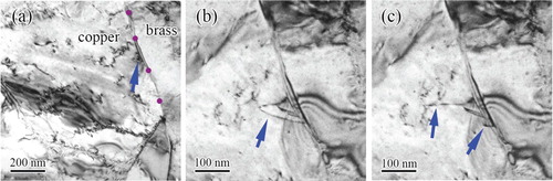
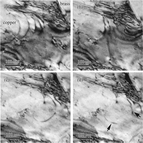
Figure shows the nucleation of twins through partial dislocation emissions from the interface and dislocation interactions with the twins (Supplementary Movie 2). Figure (a) shows a staking fault growing from the interface by a slipping partial. The stacking fault is on an inclined {111} slip plane, which produced parallel Moiré fringes. It intersects both the top and bottom surfaces, making it look like a ribbon. It appeared narrow because it has a large inclination angle to the surface. Upon further straining, two more partials are emitted in adjacent planes, but at varying distances from the interface (Figure (b)), which formed a twin with a two-layer segment as marked by the blue arrow and a three-layer segment as indicated by the green arrow. Further straining moved the three partials close to the twinning front (Figure (c)), while a dislocation is interacting with the twin (see the orange arrow). The dislocation caused local detwinning (Figure (d), blue arrow). The detwinning mechanism by a perfect dislocation can be found in our earlier work [Citation22].
Figure 2. Twin nucleation and growth from the domain interface and twin-dislocation interactions. (a) A stacking fault nucleated from the interface. (b) A three-layer deformation twin (green arrow) changes to two layers near the growth end (blue arrow). (c) A perfect dislocation interacting with the twin (orange arrow). (d) Detwinning caused by a dislocation (blue arrow). (e) Second twin from the interface and dislocations emitted from a Fran-Read source between the two twins. (f) Strain field near the interface.
Further straining leads to the nucleation and growth of another twin, which is shorter and parallel to the first twin (Figure (e)). The second twin has three layers spaced at a distance from each other, suggesting that they repel each other. In other words, they may have the same Burgers vector. Therefore, this twin is likely formed by the monotonic emission of partials from the interface, and will produce a twinning strain [Citation23]. Interestingly, there is a Frank–Read source between the two twins, which emitted perfect dislocations toward the interface. We propose a possible mechanism for the Frank–Read source to operate between the two twins (Supplemental Figure S6). Figure (f) indicates extensive interactions between dislocations and twins near the interface, which produced a high intensity and complex strain field.
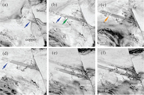
Frank–Read dislocation sources were found dynamically formed, and deactivated after emitting some dislocations (Supplementary Movie 3). A total of ten Frank–Read sources were observed at a different stage of straining (Supplemental Figures S7–S14). These dislocations typically glide toward and piled up against the interface. When a Frank–Read source was deactivated, the dislocation pileup associated with it often disappears. Figure (a) shows five dislocations that were emitted from a Frank–Read source and piled up against the interface. Upon further straining, the Frank–Read source was deactivated with only two remnant dislocations left (Figure (b)). Note that these dislocations slipped for a relatively long distance without encountering the sample surface, indicating that they are on a {111} slip plane that is almost parallel to the sample surface. Figure (c) shows another Frank–Read source that was formed after the one in Figure (a) was deactivated. As shown, a half dislocation loop was formed. However, with further straining the dislocation loop reached the surface, and was broken into two segments as indicated by two black arrows. This indicates that the slip plane of this Frank–Read source is different from those discussed earlier.
Figure 3. Dynamic nucleation and deactivation of Frank–Read sources. (a) A Frank–Read source produced five dislocations piling-up against the interface, (b) The deactivation of the dislocation source; (c) Another Frank–Read source was activated and emitted a dislocation loop. (d) The dislocation loop was broken at the sample surface.
The in-situ TEM observation here solved three critical issues in dislocation-interface interactions. The first is the mechanism for the formation of the negative strain gradient near the interface. GNDs are responsible for producing the back-stress observed in heterostructured materials [Citation8,Citation24,Citation25]. It is generally believed that in coarse-grained metals Frank–Read sources in grain interior are main dislocation sources [Citation26–28]. If the dislocations emitted from a Frank–Read source piles up against an interface, they become the type of GNDs that produce long-range back stress [Citation25]. The other type of GNDs is those that form low-angle grain boundaries, which do not produce back-stress. For dislocation pile-up, the plastic strain increases from the interface to the Frank–Read source, which hereafter we refer to as the positive strain gradient. The plastic strain at the interface is zero if no dislocation is pushed into the interface. It was recently observed that a negative strain gradient exists near the Cu–brass interface [Citation13], which is opposite to the above Frank–Read source scenario. Therefore, it was concluded that interfaces were the dislocation sources [Citation13], which is consistent with the decades-old minority view that dislocation ledges at grain boundaries are the primary dislocation sources [Citation14,Citation17].
In the current in-situ TEM observation, only two perfect dislocations and two thin twins were observed emitted from the interface, as compared to about ten Frank–Read sources that were dynamically generated, each emitting a number of dislocations toward the interface before being eventually deactivated. The dislocation pileups mostly disappeared after the deactivation of the dislocation sources. These observations indicate that the Frank–Read sources are primarily responsible for the observed negative strain gradient. Logically, since most Frank–Read sources did not produce GND pile-up, only the density gradient of the Frank–Read sources can produce the observed negative strain gradient since the dislocation pileup will produce a positive strain gradient. Since both dislocation density and stresses are higher as it gets closer to the interface, it is logically reasonable to hypothesize that the closer to the interface, the higher probability to generate Frank–Read sources. This will produce the observed density gradient of the Frank–Read sources to yield a negative strain gradient. This hypothesis is verified by analyzing the distances of Frank–Read sources from the interface (Supplemental Figure S15).
The second long-standing issue possibly solved here is whether Frank–Read source plays a primary role in the plastic deformation of coarse-grained metals. The majority view in textbooks is that Frank–Read sources are primarily responsible in coarse-grained metals [Citation26,Citation28,Citation29], while grain boundaries may become the dominant dislocation source in nanocrystalline metals [Citation4, Citation30–35]. However, Murr [Citation14] argued that Frank–Read sources rarely exist in the grain interior and grain boundary ledges are the primary dislocation sources, as proposed by Li in 1961 [Citation17]. Murr used postmortem TEM observations [Citation36] to support his hypothesis. The in-situ TEM observations here clearly indicate that dynamic Frank–Read sources are the primary dislocation sources in coarse-grained Cu, and postmortem TEM observations are not reliable since the Frank–Read sources are dynamically generated and deactivated during the deformation process, which leaves behind little evidence for postmortem TEM observation.
The third issue solved here is the relationship between the strain gradient and GND density gradient. It is believed that the strain gradient has to be accommodated by GNDs [Citation37], which hints at a quantitative relationship between the magnitude of strain gradient and GND density gradient. The dynamic nature of Frank–Read sources and the disappearance of dislocation pileups make it necessary to revise the current strain plasticity theory [Citation37] as well as our understanding of the relationship between the strain gradient and back-stress evolution [Citation25]. Specifically, the strain gradient near the interface is related to the density gradient of Frank–Read sources, not directly to the GND density gradient, although a GND density gradient was indeed developed [Citation9]. Since most GNDs are destroyed instead of being accumulated, with increasing applied strain it can be logically expected that the increase in GND pileups will slow down and eventually reach a dynamic saturation, which will lead to a corresponding slowing down and saturation of back stress. This was exactly what has been observed in heterostructured materials [Citation8,Citation9].
The dynamic nature of the Frank–Read sources is surprising but can be understood with the concept of dislocation intersections [Citation26,Citation29]. When two dislocations gliding on different slip planes intersect each other, they will produce jogs in the other dislocation line. The magnitude and orientation of the jog in one dislocation line equal those of the Burgers vector of the other dislocation (see Figure (a)). Since the jog is not on the original slip plane of the dislocation, it acts to pin the dislocation line, a scenario that has been observed in the current in-situ TEM experiment (Supplemental Figure S4). If two jogs are formed along with a gliding dislocation and their spatial distance are large enough for the dislocation segment between them to bow out to emit dislocations under the local stress, a Frank–Read source will be generated (Figure (b,c)). Considering the large number of slip systems on the four {111} planes in fcc Cu, the probability of forming such Frank–Read sources should be very high, which is why so many Frank–Read sources were observed during the in-situ TEM experiments.
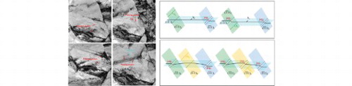
Figure 4. Schematic diagram of dynamic nature of the Frank–Read source. (a) Intersection of two dislocations gliding on different slip planes, (b) Two pinning jogs formed along a gliding dislocation, (c) A Frank–Read source is generated to emit dislocations under the local stress, and (d) The Frank–Read source is deactivated by a new jog formed between the two pinning jogs.
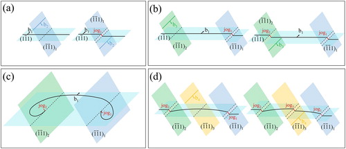
The Frank–Read source could be deactivated if a new jog forms on the dislocation segment between the two pinning jogs, in which the local stress may no longer be able to bow out the shorter remaining free dislocation segments. The critical shear stress needed to activate a Frank–Read source is [Citation26].
(1)
(1) where G is the shear modulus, b is the Burgers vector magnitude and d is the distance between two pinning points. When a new pinning point is formed on the dislocation line between the two original pinning points, d will decrease and the critical stress needed to bow out the shorter dislocation segment will increase, leading to the deactivation of the Frank–Read source (Figure (d)). We have indeed observed many dislocation segments that cannot emit dislocations because they are too short.
It should be noted that TEM observations can only be performed on thin films [Citation38]. This casts some uncertainty on our in-situ TEM results since the thin film may be under different stress state from the bulk, and the free surfaces may affect dislocation slip. We note that the current observations can be logically explained using current textbook knowledge without invoking thin film, and believe that the results at least qualitatively reflect the physics of dislocation interaction with domain interfaces. Nevertheless, more study is needed, possibly by computer modeling.
The probability of observing dislocation pile-ups is affected by the tendency for planar slip, which is in turn affected by stacking fault energy (SFE), and lattice friction caused by solute atoms [Citation39]. Pure Cu is a wavy slip material [Citation39], meaning easy dislocation cross-slip, which is largely responsible for the observed disappearance of dislocation pile-ups.
Low SFE makes it difficult for a perfect dislocation to cross-slip, meaning stable dislocation pile-ups. Indeed, we have observed extensive dislocation pile-ups in 304L stainless steel (Supplemental Figure S5), which has lower SFE (18 mJ/m2) [Citation40] than Cu (54.6 mJ/m2) [Citation4]. Since GND piling-up can effectively produce back stress [Citation25], it can be logically deduced that low SFE should promote back-stress hardening to produce superior mechanical properties. Lastly, back-stress hardening has been recently renamed hetero-deformation induced (HDI) hardening for more precise description of physics [Citation41].
Supplemental Material
Download QuickTime Video (13 MB)Supplemental Material
Download QuickTime Video (21.3 MB)Supplemental Material
Download QuickTime Video (1.9 MB)Supplemental Material
Download MS Word (6.1 MB)Disclosure statement
No potential conflict of interest was reported by the authors.
Additional information
Funding
References
- Ovid′ko IA, Valiev RZ, Zhu YT. Review on superior strength and enhanced ductility of metallic nanomaterials. Prog Mater Sci. 2018;94:462–540.
- Wang YM, Chen MW, Zhou FH, et al. High tensile ductility in a nanostructured metal. Nature. 2002;419:912–915.
- Wei YJ, Li YQ, Zhu L, et al. Evading the strength-ductility trade-off dilemma in steel through gradient hierarchical nanotwins. Nat Commun. 2014;5:3580.
- Zhu YT, Liao XZ, Wu XL. Deformation twinning in nanocrystalline materials. Prog Mater Sci. 2012;57:1–62.
- Lu K, Lu L, Suresh S. Strengthening materials by engineering coherent internal boundaries at the nanoscale. Science. 2009;324(5925):349–352.
- Araki K, Takada Y, Nakaoka K. Work-hardening of continuously annealed dual phase steels. Trans Iron Steel Inst Jpn. 1977;17:710–717.
- Kundu A, Field DP. Influence of plastic deformation heterogeneity on development of geometrically necessary dislocation density in dual phase steel. Mater Sci Eng A. 2016;667:435–443.
- Wu XL, Yang MX, Yuan FP, et al. Heterogeneous lamella structure unites ultrafine-grain strength with coarse-grain ductility. Proc Natl Acad Sci USA. 2015;112:14501–14505.
- Ma XL, Huang CX, Moering J, et al. Mechanical properties in copper/bronze laminates: role of interfaces. Acta Mater. 2016;116:43–52.
- Chassagne M, Legros M, Rodney D. Atomic-scale simulation of screw dislocation/coherent twin boundary interaction in Al, Au, Cu and Ni. Acta Mater. 2011;59:1456–1463.
- Kondo S, Mitsuma T, Shibata N, et al. Direct observation of individual dislocation interaction processes with grain boundaries. Science Adv. 2016;2(11):1501926.
- Kacher J, Eftink BP, Cui B, et al. Dislocation interactions with grain boundaries. Curr Opin Solid State Mater Sci. 2014;18:227–243.
- Huang CX, Wang YF, Ma XL, et al. Interface affected zone for optimal strength and ductility in heterogeneous laminate. Mater Today. 2018;21(7):713–719.
- Murr LE. Dislocation ledge sources: dispelling the myth of Frank-Read source importance. Metall Mater Trans A. 2016;47(12):5811–5826.
- Mompiou F, Legros M, Boé A, et al. Inter- and intragranular plasticity mechanisms in ultrafine-grained Al thin films: an in situ TEM study. Acta Mater. 2013;61:205–216.
- Wang LW, Han XD, Liu P, et al. In situ observation of dislocation behavior in nanometer grains. Phys Rev Lett. 2010;105:135501.
- Li JCM. High-angle tilt boundary – a dislocation core model. J Appl Phys. 1961;32(3):525–530.
- Wang LH, Teng J, Sha XC, et al. Plastic deformation through dislocation saturation in ultrasmall Pt Nanocrystals and its in situ atomicstic mechanisms. Nano Lett. 2017;17(8):4733–4739.
- Wang LH, Zhang Z, Ma E, et al. Transimission electron microscopy observations of dislocation annihilation and storage in nanograins. Appl Phys Lett. 2011;98(5):051905.
- Liu P, Mao SC, Wang LH, et al. Direct dynamic atomic mechanisms of strain-induced grain rotation in nanocrystalline, textured, columnar-structured thin gold films. Scr Mater. 2011;64(4):343–346.
- Han XD, Wang LH, Yue YH, et al. In situ atomic scale mechanical microscopy discovering the atomistic mechnisms of plasiticty in nano-single crystals and grain rotation in polycrystalline metal. Ultramicroscopy. 2015;151:94–100.
- Zhu YT, Wu XL, Liao XZ, et al. Dislocation-twin interactions in nanocrystalline fcc metals. Acta Mater. 2011;59:812–821.
- Wu XL, Liao XZ, Srinivasan SG, et al. New deformation twinning mechanism generates zero macroscopic strain in nanocrystalline metals. Phys Rev Lett. 2008;100:095701.
- Ma E, Zhu T. Towards strength-ductility synergy through the design of heterogeneous nanostructures in metals. Mater Today. 2017;20(6):323–331.
- Wu XL, Zhu YT. Heterogeneous materials: a new class of materials with unprecedented mechanical properties. Mater Res Lett. 2017;5(8):527–532.
- Hirth JP, Lothe J. Theory of dislocations. Malabar (FL): Krieger Publishing Company; 1992.
- Hertzberg RW. Deformation and fracture mechanics of engineering materials. New York: Wiley; 1989.
- Frank FC, Read WT. Multiplication processes for slow moving dislocations. Phys Rev. 1950;79:722–723.
- Hull D, Bacon DJ. Introduction to dislocations. Oxford: Pergamon Press; 1984.
- Yamakov V, Wolf D, Phillpot SR, et al. Deformation mechanism crossover and mechanical behaviour in nanocrystalline materials. Philos Mag Lett. 2003;83:385–393.
- Yamakov V, Wolf D, Phillpot SR, et al. Deformation-mechanism map for nanocrystalline metals by molecular-dynamics simulation. Nature Mater. 2004;3:43–47.
- Swygenhoven HV, Weertman JR. Deformation in nanocrystalline metals. Mater Today. 2006;9(5):24–31.
- Swygenhoven HV, Derlet PM, Froseth AG. Stacking fault energies and slip in nanocrystalline metals. Nature Mater. 2004;3:399–403.
- Wang LH, Teng J, Liu P, et al. Grain rotation mediated by grain boundary dislocations in nanocrystalline platinum. Nat Commun. 2014;5:4402.
- Wang LH, Xin TJ, Kong DL, et al. In situ observation of stress induced grain boundary migration in nanocrystalline gold. Scr Mater. 2017;134:95–99.
- Murr LE, Wang SH. Comparison of microstructural evolution associated with the stress-strain diagrams for nickel and 304 stainless steel: an electron microscope study of micro-yielding and plastic-flow. Res Mech. 1982;4:237–274.
- Gao H, Huang Y, Nix WD, et al. Mechanism-based strain gradient plasticity-I. Theory. J Mech Phys Solids. 1999;47(6):1239–1263.
- Mompiou F, Caillard D, Lergos M, et al. In situ TEM observations of reverse dislocation motion upon unloading in tensile-deformed UFG aluminum. Acta Mater. 2016;60:3402–3414.
- Hong SI, Laird C. Mechanisms of slip mode modification in F. C.C. solid-solutions. Acta Metall Mater. 1990;38(8):1581–1594.
- Lee TH, Shin E, Oh CS, et al. Correlation between stacking fault energy and deformation microstructure in high-interstitial-alloyed austenitic steels. Acta Mater. 2010;58:3173–3186.
- Zhu YT, Wu XL. Perspective on hetero-deformation induced (HDI) hardening and back stress. Mater Res Lett. In press.