
 ?Mathematical formulae have been encoded as MathML and are displayed in this HTML version using MathJax in order to improve their display. Uncheck the box to turn MathJax off. This feature requires Javascript. Click on a formula to zoom.
ABSTRACT
Patterns on sand generated by blowing winds are one of the most commonly seen phenomena driven by such a self-organization process, as has been observed at the nanoscale after ion irradiation. The origins of this effect have been under debate for decades. Now, a new methodology allows to simulate directly the ripple formation by high-fluence ion-irradiation. Since this approach does not pre-assume a mechanism to trigger self-organization, it can provide answers to the origin of the ripple formation mechanism. The surface atom displacement and a pile-up effect are the driving force of ripple formation, analogously to the macroscopic one.
IMPACT STATEMENT
The presented model allows to follow the ripple formation and propagation in different steps, at the atomic level, for the first time under low irradiation energies.
GRAPHICAL ABSTRACT
KEYWORDS:
Introduction
Self-organization effects are observed in many fields of science, and have the fascinating feature that similar effects can sometimes be observed in systems differing over many orders of magnitude in length and time scales. One such self-organization effect is that of ripple formation on surfaces. This effect is most commonly seen when caused by a moderate wind blowing on water or sand, or water flowing on sandy river bottoms [Citation1]. Surprisingly, ripple formation has also been seen on the surfaces of solids at the nanoscale after prolonged energetic ion irradiation [Citation2–7]. A number of ripple formation models based on the numerical solution of differential equations have been developed to explain the phenomenon. The theory proposed by Bradley and Harper [Citation8], later extended by many other groups, explained the rippling effect as the modification of surface curvature due to sputtering under inclined incidence (if this indeed is the dominant mechanism, then the similarity between ion- and wind-induced ripples is only coincidental). After the surface morphology has changed, the sputtering rate may also change. A few studies have taken into account this effect as a non-linear extension term related to the erosion rate [Citation9–14]. However, it was recently shown the erosive component alone is not able to capture the complex phenomenon [Citation15,Citation16]. Norris et al. [Citation17,Citation18] proposed a mathematical model predicting patterns based on the crater function formalism, which allows also describing atom redistribution as an additional term contributing to ripple formation. Nevertheless, none of the analytical theories is able to capture the full process of self-organization or provide an intuitive understanding of its driving mechanisms.
Molecular dynamics (MD) computer simulations of sequential ion impacts can, in principle, describe all the processes taking place concurrently under the ion irradiation condition, and give invaluable insights on the complexity of their interplay. MD simulations have indeed been used to provide important and clarifying insights on built-up stress [Citation19,Citation20] and its relation to ripple formation [Citation21,Citation22]. However, due to the very high computational costs of MD simulations of tens of thousands of keV ion impacts, direct formation and propagation of ripples have until now not been reproduced by this technique. Refs. [Citation23,Citation24] even directly state that MD simulations are not suited for studying the surface rippling due to time and size limitations. However, in recent experiments [Citation15,Citation25–27], it was demonstrated that the 30 eV Ar ion irradiation caused the ripple formation on the surface of amorphous Si as well. In the current work, we gain new insights on the process of ripple formation due to a unique combination of a recently developed speed-up scheme for MD simulation [Citation28] to simulate tens of thousands of ion impacts on the same surface, with consideration of the new experimental condition of very low ion energy-induced ripples. The application of this new MD scheme enables us to observe directly the ripple formation and propagation by atomic self-organization at low energy irradiation, and to show that under negligible sputtering, the accumulation of displacement is the driving force of the ripple propagation similar to that observed experimentally.
Materials and methods
The simulations performed in this study were carried out using PARCAS MD code [Citation29,Citation30]. The relaxation process performed to obtain the a-Si structure used in this work is explained in detail in Appendix. More detail can be found in Refs. [Citation15,Citation31]. The size of the flat-surface cell used as a starting point ; it contained 73,584 atoms.
The consecutive 50,000 impacts by 30 eV Ar ions were effectively simulated at random points of the surface using a fixed azimuthal angle parallel to the x-axis. This was achieved by randomly shifting the cell in x- and y-directions over the periodic boundaries prior to each impact. The impact point was always located in the center of the cell far from the border to reduce undesired high energy interactions over the periodic boundaries. The irradiation angle (θ) is 70 off-normal. This temperature was restored to 300 K in the system after every nine impacts (1 ps long) using the Berendsen thermostat [Citation32] during 30 ps.
Results
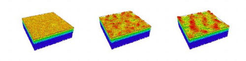
Results on the evolution are shown in snapshots in Figure , taken after 9000, 27,000 and 50,000 Ar impacts, respectively. The continuous evolution is also illustrated in a movie, see Supplementary-Movie-1.mp4. Here the atoms are colored according to their z-coordinate (perpendicular to the surface). As we observe in this figure, the prolonged ion irradiation leads initially to random surface roughening. The second frame shows the emerging pattern that becomes fully clear in the last snapshot. The atoms on the ripple crests (the highest z-coordinates) clearly experienced the largest displacements, as shown in Figure (a). The further increase of the fluence promotes the propagation of the formed ripples.
Figure 1. Evolution of the initially flat surface ((a) 9000 (fluence: ), (b) 27000 (
) and (c) 50000 (
) impacts) under random impact 30 eV-Ar
at
.
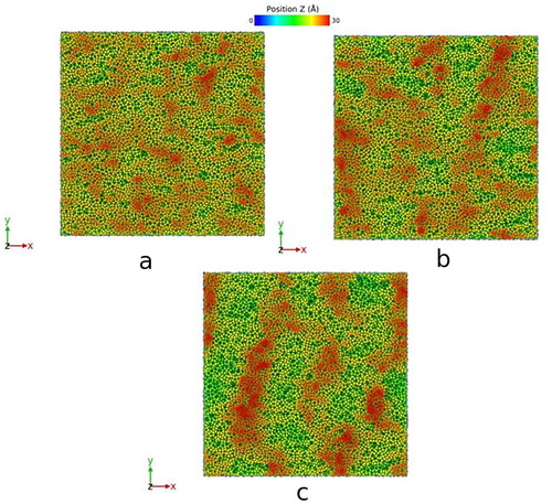
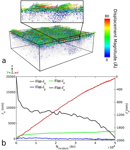
Figure 2. (a) Displacement vectors (located at the final position and shortened by a factor of 1/5 for clearer observation) from the initial configuration. The black rectangle represents a closer view of the displacement vectors (shortened by a factor of 1/2) in one of the ridge areas (a 1.5 nm-thickness slice in the y-direction). (b) Evolution of the different components of the displacement vectors δ (on the left vertical axis) and only negative contribution in the x-direction (on the right vertical axis) as a function of the number of incoming ions.
Hence, a detailed analysis of surface evolution with the ion fluence may shed the light on atomic-level mechanisms driving the self-organization process.
First, we analyze the role of erosive mechanism in ripple formation. We observe a linear increase in the number of sputtered atoms with the fluence. We estimate the average sputtering yield . However, when we compare this value to the one obtained in the previous study [Citation15] for the single impact calculations (
), we see that the increased curvature of the increasingly roughened surface does not affect significantly the sputtering yield and it remains within the error bars. We measure the role of erosion by analyzing the amount of missing atoms in the trough of the ripple, excluding the volume of its crest. The empty volume below the original surface can be found by using the OVITO surface mesh tool [Citation33] similarly to Ref. [Citation16]. The estimated difference in solid volume between the initial and the final configurations results in approximately 4500 atoms. The total number of sputtered atoms during the entire simulation did not exceed 1500. Assuming that the crest is generated by the re-deposited atoms, about 3000 atoms more would need to participate in the sputtering process, which may have ended in re-deposition. Hence, we conclude that the erosion can be safely excluded from the consideration as a prime mechanism of ripple formation at low incident energy. Note that at higher incident energies the sputtering is stronger and may play a more substantial role in pattern formation.
Next, we analyze the total displacement of atoms in a cascade that is found as , where
are the atom coordinates and
is the number of atoms displaced in a cascade. In Figure (b), we draw the evolution of all three components of the total displacement,
,
(fluctuates around zero due to symmetry considerations) and
. In Figure (a) and it is noticed that most of the displacement accumulation takes place at the surface.
grows slowly in the positive z-direction (outwards from the surface). In the cascades, the atoms are displaced in all directions, however, the displacements towards the open surface are generally larger due to stress relaxation effects at the surface. Moreover, some atoms receive the momentum in the direction out, however, the transfered energy is not sufficient to overcome the surface barrier and sputter. Instead the atoms climb above the initial surface layer adding to the positive component of the
.
In Figure (b), we observe that the largest component of the total displacement is (parallel to the ion-beam projection). The strong momentum transfer in the direction of the ion beam (positive x-direction) causes strong growth of
with the fluence. Since
, the shape of
is very similar to
. On the other hand, one might expect only small or no change of
with fluence, since the negative displacements are significantly shorter and have little driving force for accumulation.
Initially, (Figure (b), the right y-axis) decreases linearly fast during the first few hundreds of ion impacts. This linear decrease reflects the accumulation of the total displacement in non-overlapping cascades (see Figure B2 in Appendix). The linear behavior continues until the shape of the surface changes. The ions which hit on the front, induce mainly stronger forward displacements. The ions impacting on the back slopes partially compensate for this effect, as they mainly scatter from the surface (grazing incidence), inducing backward atomic displacements. This is why
still decreases but with a slightly reduced rate.
The picture changes when the cascades begin overlapping with previously affected regions. The total negative displacement does not decrease almost at all due to compensation by the from the following cascades (
can even occasionally increase). The same process slows down the increase of
, inducing non-linear growth of this component. This continues until about 27,000–30,000 impacts, when both surfaces became equally rough. Notice that, eventually, on average the crest-trough distance is about 1.5 nm, similar to the one measured in Ref. [Citation15].
To verify the model, we performed the simulations for the 85 incidence as well. The results showed the expected pattern of the ripples in the perpendicular mode (details to be published elsewhere).
Discussion
The analysis of the induced total displacement shows that indeed this parameter reflects the overall behavior of the atomic system.
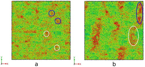
To understand the different steps of the ripple formation, we focused only on the atoms that eventually form a ripple, following their history from the original positions on the initially flat surface. First, we saw that the motion of these atoms can be described as a biased random walk. In other words, we observe a diffusion-like process of atom migration on the surface. However, thermal diffusion at room temperature is well beyond the time span of MD simulations employed in this work, hence it cannot be used to explain the observed results. Nonetheless, the momentum received by the atoms in cascades stimulates migration of atoms more intensively on the surface than under it. Moreover, the strong momentum component in the x-direction induces a clear bias in this direction. This random motion of atoms creates initial random roughening on the surface, see Figure (a). In the following cascades, redistribution of the atoms within the forming random mounds triggers the displacement of the mound as a whole. In some cases, the formed mounds can be destroyed, however, the larger the rough feature grows, the less susceptible it becomes to destruction. While moving on the surface as a cluster, the mounds merge together forming a single ridge impeding the further motion of separate parts, see Figure (b).
Figure 3. (a) Several initial mounds (colored circles) after 18900 Ar impacts (fluence:
) that eventually meet in a final ridge (b) at 45540 Ar
impacts (
).
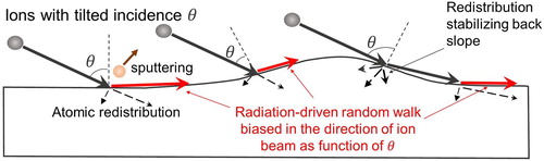
We also notice that the forward momentum transferred by the ion to the surface atoms depends on the effective incidence angle θ. The smaller the θ, the smaller the forward momentum and the shorter the displacement is induced by ion. However, on the back slope of a mound or a ridge, the ion hits at a grazing incidence which does not transfer to the surface atoms the momentum forward, but rather the momentum inwards stabilizing the back slope. This observation explains the pile-up effect and why the formed mounds and ridges survive and do not flatten down by the impacting ions (this process can be seen in Supplementary-Movie-1.mp4 and Supplementary-Movie-2.mp4). In Figure , we summarize the mechanism of ripple formation omitting for clarity the motion of separate mounds prior a ridge formation.
Figure 4. Illustration of the biased surface atom diffusion induced by ion beam after initial random roughening of the surfaced based on observations from the simulations.
We note here that this process of the radiation-induced biased random walk motion does not require relaxation of internal stresses. However, we analyzed the stress buildup in our simulation cell and found no correlation with the ripple formation. The stress builds up under the surface in the direction of ion beam ( kbar), but it changes the sign in the direction perpendicular to the surface (
kbar) (see Appendix).
The Carter and Vishnyakov model [Citation34], explained the ripple formation by atom relocation as well but fails to capture the propagation of the ripples, since it does not consider the movement of whole mounds initially formed by piling-up of displaced surface atoms. Our simulation follows all stages of the process: from atom relocation to piling-up and merging of mounds into larger structures eventually forming a continuous ripple, which continues propagating, coarsening and slowing down as well.
As a final point of discussion, we note that this explanation of ripple formations shows that, despite the almost ten orders of magnitude different length scale, there is indeed an analogy of the ion-induced ripple formation mechanism with that of macroscopic ripples on water and sand. Although there are many mechanisms that may cause the macroscopic ripples, the base factors causing these include redeposition of material due to an external driving force [Citation1], in clear analogy with the diffusion-like flow and pile-up effects shown here to occur for an ion-induced driving force. The pile-up effect at the first stages of the simulation can be seen as a product of saltation and reptation processes [Citation35], by analogy of the atoms with sand grains, for instance. However, from this point, we observe a merge of these initial mounds in larger structures due to a reptation-like biased movement, explained in Figure .
In summary, using MD simulations we observed directly the pattern formation at low energy (30 eV) irradiation by Ar ions on a-Si. The observed self-organization was mainly triggered by the radiation-driven random walk biased in the direction of the projection of the ion beam (x-direction) at 70
off-normal incidence. In the present simulations with low incident energy, we observe a strong effect of atomic redistribution due to collision cascades on ripple formation, but weaker dependence on sputtering or stress buildup. The slowing down in the growth dynamics is explained by increasingly overlapping cascades, where the previous forward displacements are compensated by the backward displacements of the newly coming cascades. Detailed analysis of the origin of the atoms comprising the final ridge revealed that self-organization is fully explained by pile-up and irradiation-enhanced migration of surface atoms.
Supplemental Material
Download PDF (227.4 KB)Disclosure statement
No potential conflict of interest was reported by the authors.
ORCID
A. Lopez-Cazalilla http://orcid.org/0000-0002-9365-4294
F. Djurabekova http://orcid.org/0000-0002-5828-200X
C. Fridlund http://orcid.org/0000-0002-2424-1912
K. Nordlund http://orcid.org/0000-0001-6244-1942
Additional information
Funding
References
- Fourriere A, Claudin P, Andreotti B. Bedforms in a turbulent stream: formation of ripples by primary linear instability and of dunes by nonlinear pattern coarsening. J Fluid Mech. 2010;649:287–328. doi: 10.1017/S0022112009993466
- Cunningham RL, Haymann P, Lecomte C, et al. Etching of surfaces with 8-keV argon ions. J Appl Phys. 1960;31(5):839–842. doi:10.1063/1.1735705
- Navez M, Sella C, Chaperot D. Etude de l'attaque du verre par bombardement ionique. C R Acad Sci Paris. 1962;254:240.
- Facsko S, Dekorsy T, Koerdt C, et al. Formation of ordered nanoscale semiconductor dots by ion sputtering. Science. 1999;285:1551–1553. doi: 10.1126/science.285.5433.1551
- Valbusa U, Boragno C, Buatier de Mongeot F. Nanostructuring surfaces by ion sputtering. J Phys. 2002;14:8153.
- Cuenat A, George HB, Chang K-C, et al. Lateral templating for guided self-organization of sputter morphologies. Adv Mater. 2005;17:2845–2849. doi: 10.1002/adma.200500717
- Ziberi B, Frost F, Hoche T, et al. Ripple pattern formation on silicon surfaces by low-energy ion-beam erosion: experiment and theory. Phys Rev B. 2005;72:235310. doi: 10.1103/PhysRevB.72.235310
- Bradley RM, Harper JM. Theory of ripple topography induced by ion bombardment. J Vac Sci Technol. 1988;6:2390–2395. doi: 10.1116/1.575561
- Cuerno R, Barabasi A-L. Dynamic scaling of ion-sputtered surfaces. Phys Rev Lett. 1995;74:4746–4749. doi: 10.1103/PhysRevLett.74.4746
- Makeev MA, Barabasi A-L. Ion-induced effective surface diffusion in ion sputtering. Appl Phys Lett. 1997;71:2800–2802. doi: 10.1063/1.120140
- Makeev MA, Cuerno R, Barabasi A-L. Morphology of ion-sputtered surfaces. Nucl Instrum Methods Phys Res B. 2002;197:185–227. doi: 10.1016/S0168-583X(02)01436-2
- Makeev MA, Barabasi A-L. Effect of surface morphology on the sputtering yields. I. Ion sputtering from self-affine surfaces. Nucl Instrum Methods Phys Res B. 2004;222:316–334. doi: 10.1016/j.nimb.2004.02.027
- Castro M, Cuerno R, Vazquez L, et al. Self-organized ordering of nanostructures produced by ion-beam sputtering. Phys Rev Lett. 2005;94:016102.
- Munoz-Garcia J, Castro M, Cuerno R. Nonlinear ripple dynamics on amorphous surfaces patterned by ion beam sputtering. Phys Rev Lett. 2006;96:086101. doi: 10.1103/PhysRevLett.96.086101
- Lopez-Cazalilla A, Chowdhury D, Ilinov A, et al. Pattern formation on ion-irradiated Si surface at energies where sputtering is negligible. J Appl Phys. 2018;123:235108. doi: 10.1063/1.5026447
- Lopez-Cazalilla A, Ilinov A, Djurabekova F, et al. Modeling of high-fluence irradiation of amorphous Si and crystalline Al by linearly focused Ar ions. J Phys. 2019;31:075302.
- Norris SA, Brenner MP, Aziz MJ. From crater functions to partial differential equations: a new approach to ion bombardment induced nonequilibrium pattern formation. J Phys. 2009;21(22):224017.
- Norris SA, Samela J, Madi CS, et al. MD-Predicted phase diagrams for pattern formation. Nat Commun. 2011;2:276. doi: 10.1038/ncomms1280
- Koster M, Urbassek HM. Modification of a-si under 100 ev si atom bombardment. Nucl Instrum Methods Phys Res B. 2001;180:299–305. doi: 10.1016/S0168-583X(01)00435-9
- Moreno-Barrado A, Castro M, Gago R, et al. Nonuniversality due to inhomogeneous stress in semiconductor surface nanopatterning by low-energy ion-beam irradiation. Phys Rev B. 2015;91:155303. doi: 10.1103/PhysRevB.91.155303
- Norris SA. Stability analysis of a viscoelastic model for ion-irradiated silicon. Phys Rev B. 2012;85:155325. doi: 10.1103/PhysRevB.85.155325
- Norris SA. Stress-induced patterns in ion-irradiated silicon: model based on anisotropic plastic flow. Phys Rev B. 2012;86:235405. doi: 10.1103/PhysRevB.86.235405
- Süle P, Heinig KH. The molecular dynamics simulation of ion-induced ripple growth. J Chem Phys. 2009;131:204704. doi: 10.1063/1.3264887
- Yewande EO, Kree R, Hartmann AK. Numerical analysis of quantum dots on off-normal incidence ion sputtered surfaces. Phys Rev B. 2007;75:155325. doi: 10.1103/PhysRevB.75.155325
- Metya A, Ghose D. Investigation of ion beam induced nanopattern formation near the threshold energy. Appl Phys Lett. 2013;103:161602. doi: 10.1063/1.4825280
- Chowdhury D, Ghose D, Mollick SA. Homoepitaxy of germanium by hyperthermal ion irradiation. Vacuum. 2014;107:23–27. doi: 10.1016/j.vacuum.2014.03.022
- Chowdhury D, Ghose D, Mollick SA, et al. Nanorippling of ion irradiated GaAs (001) surface near the sputter-threshold energy. Phys Status Solidi B. 2015;252:811–815. doi: 10.1002/pssb.201451612
- Fridlund C, Laakso J, Nordlund K, et al. Atomistic simulation of ion irradiation of semiconductor heterostructures. Nucl Instrum Methods Phys Res B. 2017;409:14–18. doi: 10.1016/j.nimb.2017.04.034
- Ghaly M, Nordlund K, Averback RS. Molecular dynamics investigations of surface damage produced by keV self-bombardment of solids. Philos Mag A. 1999;79(4):795–820. doi: 10.1080/01418619908210332
- Nordlund K, Ghaly M, Averback RS. Mechanisms of ion beam mixing in metals and semiconductors. J Appl Phys. 1998;83(3):1238–1246. doi: 10.1063/1.366821
- Lopez-Cazalilla A, Ilinov A, Bukonte L, et al. Simulation of atomic redistribution effects in a-Si under ion irradiation. Nucl Instrum Methods Phys Res B. 2018;414:133–140. doi: 10.1016/j.nimb.2017.11.019
- Berendsen HJC, Postma JPM, van Gunsteren WF, et al. Molecular dynamics with coupling to an external bath. J Chem Phys. 1984;81(8):3684–3690. doi: 10.1063/1.448118
- Stukowski A. Computational analysis methods in atomistic modeling of crystals. JOM. 2014;66:399–407. doi: 10.1007/s11837-013-0827-5
- Carter G, Vishnyakov V. Roughening and ripple instabilities on ion-bombarded Si. Phys Rev B. 1996;54:17647–17653. doi: 10.1103/PhysRevB.54.17647
- Bagnold RA. The physics of wind-blown sand and desert dunes. New York: Methuen; 1941.