
 ?Mathematical formulae have been encoded as MathML and are displayed in this HTML version using MathJax in order to improve their display. Uncheck the box to turn MathJax off. This feature requires Javascript. Click on a formula to zoom.
Abstract
Large super-elasticity approaching its theoretically expected value was achieved in Ti-13.3Nb-4.6Mo alloy having an ultrafine-grained β-phase. In-situ synchrotron radiation X-ray diffraction analysis revealed that the dominant yielding mechanism changed from dislocation slip to martensitic transformation by decreasing the β-grain size down to sub-micrometer. Different grain size dependence of the critical stress to initiate dislocation slip and martensitic transformation, which was reflected by the transition of yielding behavior, was considered to be the main reason for the large super-elasticity in the ultrafine-grained specimen.
GRAPHICAL ABSTRACT

IMPACT STATEMENT
The present study clarified that ultra-grain refinement down to sub-mirometer scale made dislocation slips more difficult than martensitic transformation, leading to an excellent super-elasticity close to the theoretical limit in the β-Ti alloy.
1. Introduction
β-Ti alloys are defined as titanium alloys with sufficient amounts of β-stabilizer elements (Mo, V, Nb, etc.) to retain 100% β-phase with body-centered cubic (BCC) structure even after quenching alloys from β single-phase region to ambient temperature [Citation1]. Metastable β-phase enables stress-induced martensitic transformation (MT) and sometimes deformation twining, which leads to super-elasticity, transformation-induced plasticity (TRIP) and twining-induced plasticity (TWIP) [Citation2–4]. Such a variety of deformation characteristics has attracted intensive attention to β-Ti alloys. The super-elasticity, which is induced by reversible phase transformation between parent phase and martensite, is essential to medical-products, such as vascular and dental implants. TiNi-based alloys are one of the commonly used biomaterials due to their excellent super-elasticity. However, the existence of nickel in alloys may cause issues of hypersensitivity and toxicity, which greatly limits further medical applications. Therefore, the development of non-toxic biomedical shape memory β-Ti alloys has attracted great attentions in the last decades. For example, Miyazaki et al. [Citation5–7] have systematically evaluated the effects of adding Nb on the super-elasticity of a series of Ni-free β-Ti alloys. However, recovery strains in Ti-Nb alloys induced by reversible transformation from orthorhombic α′′ martensite to β is small, due to the small transformation strain and the low critical stress for plastic deformation(). Alloying strategy to improve super-elasticity of Ti-Nb alloys by adding Ga [Citation8], Mo [Citation9], Sn [Citation10], Ge [Citation11] and Pd [Citation12] has been recently examined. In such alloys, Otsuka [Citation13] suggested that it is necessary to increase
to improve super-elasticity, since super-elasticity is strongly inhibited by irreversible plastic deformation induced by dislocation slip in parent phase.
Grain refinement has been known as an effective way to improve yield strength of metallic materials without changing their chemical compositions, according to well-known Hall-Petch relationship [Citation14]. Recrystallization after cold-working is a conventional way to fabricate fine-grained metals. However, it is quite difficult to refine grain sizes of β-phase in β-Ti alloys due to their relatively high β-transus temperatures and rapid diffusion in BCC crystal [Citation15]. As a result, there have been little reports on super-elasticity in ultrafine-grained (UFG) β-Ti alloys as well as their MT behavior. In the present study, we have found that ultra-grain refinement of Ti-Nb-Mo alloy can enhance its super-elasticity through changing the yielding behavior.
2. Materials and methods
Ti-13.3Nb-4.6Mo (at.%) alloy was used in the present study. Plates with dimensions 30 mm long, 20 mm wide and 10 mm thick were cut from the as-received material. The alloy plate was firstly cold-rolled to 5 mm in thickness and then annealed at 830°C for 50s followed by water cooling. Then, the 5 mm thick plate was cold-rolled again to 0.6 mm in thickness(88% reduction). After the second cold-rolling, the alloy sheets were annealed at 850°C for 20 s, 80 s, or 830°C for 20 s, 30 s, and 1800 s followed by water cooling, in order to obtain different mean grain sizes of β-phase.
Microstructures of the two-step processed specimens were observed from the transverse direction (TD) of the sheets by electron back-scattering diffraction in a scanning electron microscope (SEM-EBSD) [Citation16]. Average grain sizes of β-phase () were measured by the interception method on EBSD grain boundary maps with areas large enough for statistical reliability, counting both high angle boundaries (HABs) and low grain boundaries (LABs). Tensile specimens with 11 mm gauge length, 2 mm width and 0.5 mm thickness were cut from the annealed sheets. It has been confirmed in previous studies [Citation17–19] that this small-sized specimen can give reliable data of strength and tensile ductility equivalent to those obtained from standard sized specimens of the same materials. Monotonic tensile tests were performed on Shimadzu AG-X plus system at an initial strain rate of 8.3 × 10⁻⁴ s−1 at room temperature with tensile direction parallel to the rolling direction(RD) of the sheets. Cyclic loading–unloading tensile experiments with the same strain rate were also carried out with an increment of 0.5% strain till a total tensile strain of 3.5%. In both monotonic and cyclic tensile tests, tensile strains were precisely measured by the digital image correlation method, of which details were described in [Citation20].
In-situ synchrotron radiation X-ray diffraction (SXRD) during the monotonic tensile deformation at the initial strain rate of 8.3 × 10⁻⁴ s−1 was performed on the beamline of BL46XU in SPring-8, Japan. The size of incident X-ray beam with a wavelength of 0.413 Å was 2 × 0.5 mm2, and the time resolution for data collection was 1 s. Diffraction peaks of (110), (200), (211), (220) crystallographic planes of β-phase with BCC crystal structure and (020), (021), (130), (041) planes of martensite phase with orthorhombic crystal structure were used to calculate volume fractions of martensite (VM) using Rietveld refinement method. Dislocation densities in β and deformation-induced martensite were estimated by Williamson– Hall method [Citation21].
3. Results and discussion
Microstructures of the specimens annealed after the second cold-rolling are shown in Figure . The annealing conditions and measured by the interception method on GB maps are indicated on the top of the maps. All the specimens had β single-phase microstructures. The specimen annealed at 830°C for 20 s showed elongated UFG β-grains aligned parallel to RD (Figure (a)). The interlamellar spacing of the elongated β-grains was 0.23 μm, and the fraction of LABs was 54%. The specimen annealed at 830°C for 30 s (Figure (b)) maintained an elongated morphology, but many equiaxed grains were formed by recovery and short-range grain boundary migration. The specimen annealed at 850°C for 20 s (Figure (c)) was mostly filled with ultrafine equiaxed grains. Average grain sizes (
) of the specimens shown in Figure (b,c) were 0.51 and 0.64 μm, respectively. The specimens annealed at 850°C for 80 s (Figure (d)) and 830°C for 1800 s (Figure (e)) represented typical recrystallized microstructures composed of equiaxed grains with dβ = 6.8 μm and 33.6 μm, respectively. The fraction of LABs decreased with the progress of annealing, and the recrystallized microstructures shown in Figure (d,e) were mostly composed of HABs. All the specimens showed {111}〈110〉 ∼ {111}〈112〉 textures often found in cold-rolled and annealed BCC metals, as shown in Figure A in the supplementary materials. The specimens having different dβ are referred like dβ = 0.23 μm specimen, hereafter.
Figure 1. EBSD maps of the specimens annealed under different conditions after the second cold-rolling. The first and second rows represent inverse pole figure(IPF) maps with colors indicating crystallographic orientation parallel to RD and ND of the sheets, respectively. The third row represents the grain boundary maps of the same Nareas, where LABs with misorientation angles(θ) with 2° ≦ θ < 15° and HABs with θ ≧ 15°are drawn in black and red lines, respectively.
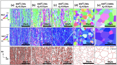
Figure (a) shows engineering stress–strain curves obtained from the monotonic tensile test of the specimens having various . In addition to the specimens of which microstructures are shown in Figure , the stress–strain curve of the
= 1.8 μm specimen with a recrystallized microstructure is included in Figure . The
= 33.6 μm specimen showed a continuous yielding behavior usually found in Ti-Nb-based alloys with coarse β single-phase microstructures. Its yield strength (0.2% proof stress), tensile strength and total elongation were 483, 574 MPa, and 46%, respectively. The yielding behavior changed from continuous yielding in the
= 33.6 μm specimen to discontinuous yielding with an obvious yield-drop in the
= 6.8 μm specimen. After reaching the upper-yield point (505 MPa), the stress quickly decreased to 469 MPa and remained nearly constant until the plastic strain of 0.041, which corresponded to Lüders-type deformation typically observed in carbon steels [Citation22, Citation23]. Tensile strength and total elongation of the
= 6.8 μm specimen were 603 MPa and 48%, respectively. When dβ became smaller than 2 μm, the stress–strain curves showed unique shapes. The
= 1.8 μm specimen showed discontinuous yielding, but the yield drop was very slight and much less sharp than that of the 6.8 μm specimen. The
= 0.64 μm specimen showed a similar shape of stress–strain curve to the 1.8 μm specimen, but the stress level increased very much by the grain refinement down to sub-micrometer scale. The
= 0.51 μm specimen no longer showed yield-drop. It exhibited continuous yielding at higher stress (0.2% proof stress of 570 MPa) followed by a limited strain-hardening. Then the flow stress quickly increased with a downward convex shape and reached a peak stress of 692 MPa at a tensile strain of 6.4%. The
= 0.23 μm specimen showed a similar but more unique shape of stress–strain curve. It exhibited a continuous yielding at 610 MPa (0.2% proof stress) followed by limited strain-hardening, then the flow stress quickly increased with a downward convex shape, and reached a peak stress of 768 MPa at a tensile strain of 5.8%. Such a ‘double yielding’ behavior has been reported in shape memory alloys, such as Ti-10V-2Fe-3Al alloy with dβ = 98.5 μm [Citation24]. It has been known that the ‘first yielding’ was ascribed to MT from β-phase and the second ‘yielding’ was ascribed to the initiation of large-scale plastic deformation by dislocation slips [Citation25]. The
= 0.23 μm specimen having the lamellar UFG morphology (Figure (a)) showed a smaller tensile ductility than the other specimens, but it showed the largest super-elasticity. It was found in the present study that the yielding behavior of the β-Ti alloy significantly and complicatedly changed with ultra-grain refinement of β-phase.
Figure 2. Engineering stress–strain curves of the specimens having different for (a) monotonic tensile test and (b) cyclic tensile tests. ϵr: recovery strain. (c) Change of ϵr of the specimens with three different
during cyclic tensile tests.
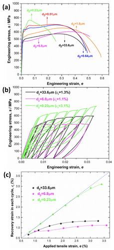
Considering the change of stress–strain curves in the monotonic tensile tests (Figure (a)), three different specimens with = 33.6, 6.8 and 0.23 μm were selected and cyclic tensile tests were carried out. Figure (b) represents engineering stress–strain curves in loading and un-loading. All the specimens showed non-linear curves in un-loading, and plastic strains remaining after complete un-loading were much smaller than the applied tensile strains just before un-loading. That is, super-elasticity appeared. The amount of recovery strain (ϵr) increased with increasing the applied strain. The grain refinement from 33.6 to 6.8 μm did not change super-elasticity. Recovery strain values of the 33.6 and 6.8 μm specimens were 1.3% and 1.1%, respectively. It was found, on the other hand, that pronounced super-elasticity was achieved in the
= 0.23 μm specimen with the lamellar UFG microstructure. The strain recovery of 3.1% in the 0.23 μm specimen was close to the theoretically expected maximum recovery strain (3.3%) calculated by Kim et al. [Citation26]. Figure (c) shows changes of the recovery strain during cyclic tensile tests. It is clearly shown that the
= 0.23 μm specimen exhibits excellent super-elasticity, compared with the other two specimens. The
= 0.23 μm specimen showed almost perfect recovery up to an applied tensile strain of 2.5%. The much smaller recovery strains in the coarser grained specimens are owing to plastic deformation by dislocation slips, as will be discussed below.
Figure 3. Results of the in-situ SXRD experiments during tensile tests of the specimens with (a,b) dβ = 6.8 μm and (c,d) dβ = 0.23 μm. (a,c) Engineering stress plus volume fraction of martensite (VM) and (b, d) engineering stress plus dislocation densities (ρ) in β and martensite are plotted as a function of the in-situ SXRD measurement time.
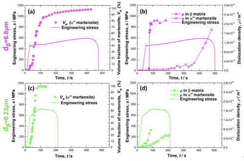
In order to understand the change in yielding behavior and super-elasticity of the specimens in detail, the in-situ SXRD experiments during monotonic tensile deformation were conducted for the = 6.8 μm and
= 0.23 μm specimens, which showed characteristic discontinuous yielding and double-yielding, respectively. Deformation-induced MT was clearly detected in SXRD profiles, and orthorhombic α″ martensite phase usually observed in Ti-Nb alloys was confirmed. Some diffraction profiles are shown in Figure B in the supplementary materials. Fractions of deformation-induced martensite (VM) and dislocation densities in β and martensite phases were evaluated from SXRD data. Results of the
= 6.8 μm and
= 0.23 μm specimen are shown in Figure (a,b) and (c,d), respectively. Initial VM in the
= 6.8 μm and
= 0.23 μm specimens was both 0%. In the
= 6.8 μm specimen that showed discontinuous yielding (Figure (a)), VM significantly increased during Lüders deformation after the yield-drop (Figure (a)). It should be noted that X-ray beam was irradiated on a limited small area in the gage part of the tensile specimen while the deformation within the gage part of the
= 6.8 μm specimen was heterogeneous in the form of Lüders deformation. Nevertheless, VM continuously increased in Figure (a), which meant that MT continuously occurred in the X-ray irradiated region regardless of the Lüders band propagation. Figure (b) shows, on the other hand, that dislocation density in β-phase in the
= 6.8 μm specimen suddenly started to increase at a certain tensile strain during Lüders deformation. This indicated that Lüders band passed at the X-ray irradiated region at the tensile strain where dislocation density suddenly increased. The dislocation density (ρ) in β quickly increased from the initial value of 4.36 × 10¹² m−2 to 1.62 × 10¹⁶ m−2, and showed nearly a constant value thereafter. The results indicated that stress-induced MT continuously occurred in the specimen while the plastic deformation within the Lüders band was given mainly by dislocation slips in β-phase. In fact, the dislocation density in martensite phase did not increase till the later stage of tensile deformation. VM in the
= 6.8 μm specimen increased to 86.4% at the Lüders strain, and then gradually increased to 99.3% at the end of tensile deformation.
In the = 0.23 μm specimen that showed double-yielding (Figure (a)), VM started to increase around the first yielding, then quickly increased to 99.7% till the second yielding, and reached almost 100% afterwards (Figure (c)). It should be noted that the
= 0.23 μm specimen had the unrecrystallized UFG lamellar microstructure (Figure (a)), so that dislocation density in β-phase of this specimen before the tensile test (2.89 × 10¹³ m−2) was higher than that in the
= 6.8 μm specimen (4.36 × 10¹² m−2) with the recrystallized microstructure (Figure (d)). The dislocation density in β-phase gradually increased after the first yielding (Figure (d)), but the values (1.25 × 10¹⁵ m−2) were one-order lower than those in the
= 6.8 μm specimen (1.62 × 10¹⁶ m−2). The results indicate that in the period between the first and second yielding, deformation was given mainly by MT and the plastic deformation of β-phase by dislocations slips was limited in the
= 0.23 μm specimen. Dislocation density in martensite increased only after the second yielding, which suggested that slip deformation in martensite was limited till the second yielding.
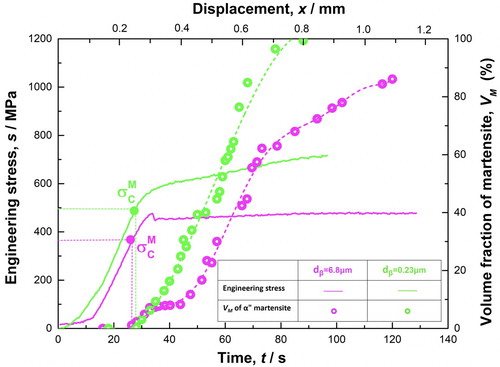
Using the in-situ SXRD data, it was possible to precisely determine the critical stress to initiate MT() in tensile deformation. Figure indicates the engineering stress and VM in the
= 6.8 and 0.23 μm specimens at early stages of tensile deformation. The values of
in the
= 6.8 and 0.23 μm specimens were 377 and 495 MPa, respectively, which were lower than the 0.2% offset stresses of the specimens. The increase of
with decreasing the grain size from
= 6.8 to 0.23 μm indicated that β was stabilized and the martensite transformation start temperature(Ms) decreased. The effect of grain size of parent phase on Ms has been reported mostly in steels [Citation14, Citation27–29]. Umemoto and Owen [Citation27] clearly showed that Ms decreased with decreasing the grain size of austenite (parent phase) in Fe-31Ni and Fe-31Ni-0.28C (wt.%) alloys, especially in the fine-grained regime. Similar trend of the decrease of Ms with grain refinement has been also shown in 0.2C-3.5Mn-1.5Si-0.5Mo (wt.%) steel by Celada-Casero et al. [Citation28]. A similar decrease of Ms temperature has been also reported in the metastable β-Ti alloys [Citation10, Citation30] which show shape memory effect and thermoelastic martensite. The stabilization of parent phase against MT by grain refinement has been understood as follows [Citation10, Citation14, Citation27–30]. The grain refinement increases the yield strength of parent phase according to Hall-Petch relationship. On the other hand, MT accompanies with shear deformation. The parent phase strengthened by grain refinement makes it difficult to accommodate shear deformation induced by MT, which leads to making MT difficult and the decrease of Ms temperature.
Figure 4. Determination of the critical stress to initiate MT in the = 6.8 μm and 0.23 μm specimens, using the in-situ synchrotron XRD results.
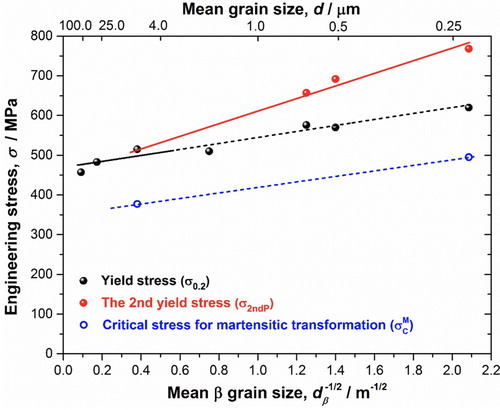
The 0.2% offset stress () was measured from Figure (a) as the (first) yield strength of the specimens with various
and obtained data were plotted as a function of
in Figure . A Hall-Petch relationship stood for
. However, we should note whether this first yield strength really corresponds to the critical stress for dislocation slips or not. In fact, Figure indicated that MT started from very early stage of tensile deformation (before 0.2% strain) in the
= 6.8 and 0.23 μm specimens. Especially in case of the UFG specimen with
= 0.23 μm which showed double yielding stress–strain curve, the dislocation density in β-phase increased only around the second yielding. Thus it would be reasonable to consider that the second yielding gives the critical stress for initiating large-scale slip deformation in the specimens showing ‘double-yielding’, as has been pointed out before [Citation24]. Peak stresses at the second yielding (
) were plotted as the 2nd yield strength corresponding to the initiation of large-scale dislocation slips in Figure . The
also showed a linear relationship, but its slope (Hall-Petch coefficient, k) was clearly larger than that for
. Such an extra Hall-Petch strengthening has been reported in various kinds of metallic materials with ultrafine grain sizes smaller than 1∼3 μm [Citation31–36]. It has been also shown that the extra Hall-Petch strengthening accompanied with discontinuous yielding [Citation31–36] like the present
= 6.8 μm specimen. We consider, therefore, that the second yield strength (
) in the present UFG specimens showing ‘double-yielding’ certainly expresses the critical stress to initiate dislocation slips, as has been reported [Citation24]. The critical stresses to initiate MT (
) obtained in Figure were also plotted in Figure . Although there were only two data points for
of the
= 6.8 and 0.23 μm specimens, the linear line connecting them showed nearly the same slope as
. Since
is lower than
, MT is expected to starts prior to dislocation slips, which coincides with the present experimental results shown in Figure . It should be noted, however, that the difference between
and
was not so large (∼100 MPa) in the
= 6.8 μm specimen, so that dislocation slips in β would also occur at early stages of deformation in the specimens with
≥ 6.8 μm. Indeed, the dislocation density in β quickly increased during Lüders deformation in the 6.8 μm specimen (Figure (b)). The occurrence of large-scale dislocation slips in β would inhibit strain recovery in unloading, i.e. super-elasticity. On the other hand, when
becomes very fine, the initiation of dislocation slip would be significantly suppressed, because the extra Hall-Petch strengthening widens the gap between
and
. This would be probably the reason why obvious ‘double-yielding’ was found only in the fine-grained specimens with
smaller than 1.8 μm (Figure (a)). The excellent super-elasticity close to the theoretically expected limit found in the
= 0.23 μm specimen could be understood by the relative easiness between MT and dislocation slip caused by the extra Hall-Petch hardening in UFG materials.
Figure 5. Hall-Petch plots for the 0.2% proof stress (), the second yield strength for dislocation slip (
) and the critical stress for MT (
) in the specimens with different
.
4. Conclusions
Ultra-grain refinement of β−matrix down to sub-micrometer grain sizes could be realized in the Ti-13.3Nb-4.6Mo alloy. The 0.23 μm grain-sized specimen showed an excellent super-elasticity (3.1%) close to the theoretically expected limit in the alloy. The in-situ SXRD during tensile deformation made it possible to precisely determine the critical stress to initiate MT. The critical stresses for MT and dislocation slips determined in the current study figured out the relative easiness of different deformation modes, i.e. MT and dislocation slips. The UFG specimens showed the extra Hall-Petch strengthening for dislocation slips, which could explain the excellent super-elasticity of the UFG specimen. The present results have given a new insight for improving super-elasticity or shape memory effect in β-Ti alloys by ultra-grain refinement.
Supplemental Material
Download MS Word (1.2 MB)Acknowledgements
For this study, NT was supported by the Elements Strategy Initiative for Structural Materials (ESISM) in Kyoto University (No.JPMXP0112101000), JSPS-KAKENHI (No.15H05767 and No.20H00306), and JST-CREST (No.JPMJCR1994). MH, DW and QS were supported by the National Key Research and Development Program of China (Grants No.2016YFB0701302 and No.2014CB644003), and the National Natural Science Foundation of China (Grants No.51671156, 51671158). YW would like to acknowledge the support from the U.S. National Science Foundation under grant number DMR-1923929. In-situ synchrotron radiation XRD experiments were conducted at beamline BL46XU of SPring-8, Harima, Japan (beam time No.2018B1760). The authors also wish to thank Northwest Institute for Non-ferrous Metal Research of China for supplying the material.
Disclosure statement
No potential conflict of interest was reported by the author(s).
Additional information
Funding
References
- Kolli RP, Devaraj A. A review of metastable Beta titanium alloys. Metal. 2018;8:506.
- Gao J, Huang Y, Guan D, et al. Deformation mechanisms in a metastable beta titanium twining induced plasticity alloy with high yield strength and high strain hardening rate. Acta Mater. 2018;152:301–314.
- Liu YJ, Zhang YS, Zhang LC. Transformation-induced plasticity and high strength in beta titanium alloy manufactured by selective laser melting. Materialia. 2019;6:100299.
- Fu Y, Xiao W, Kent D, et al. Ultrahigh strain hardening in a transformation-induced plasticity and twining-induced plasticity titanium alloy. Scr Mater. 2020;187:285–290.
- Hosoda H, Fukui Y, Inamura T, et al. Mechanical properties of Ti-Base shape memory alloys. Mater Sci Forum. 2003;426–432(4):3121–33126.
- Fukui Y, Inamura T, Hosoda H, et al. Mechanical properties of a Ti-Nb-Al shape memory alloy. Mater Trans. 2004;45:1077–1082.
- Inamura T, Fukui Y, Hosoda H, et al. Relationship between texture and macroscopic transformationstrain in severely cold-rolled Ti-Nb-Al superelastic alloy. Mater Trans. 2004;45:1083–1089.
- Kim HY, Ohmatsu Y, Kim JI, et al. Mechanical properties and shape memory behavior of Ti-Mo-Ga alloys. Mater Trans. 2004;45:1090–1095.
- Zhou T, Aindow M, Alpay SP, et al. Pseudo-elastic deformation behavior in a Ti/Mo-based alloy. Scr Mater. 2004;50:343–348.
- Grosdidier T, Philippe MJ. Deformation induced martensite and superelasticity in a β-metastable titanium alloy. Mater Sci Eng A. 2000;291:218–223.
- Inamura T, Fukui Y, Hosoda H, et al. Mechanical properties of Ti-Nb biomedical shape memory alloys containing Ge or Ga. Mater Sci Eng C. 2005;25:426–432.
- Ping DH, Mitarai Y, Yin FX. Microstructure and shape memory behavior of a Ti-30Nb-3Pd alloy. Scr Mater. 2005;52:1287–1291.
- Otsuka K, Ren X. Physical metallurgy of Ti–Ni-based shape memory alloys. Prog Mater Sci. 2005;50:511–678.
- Yang H-S, Bhadeshia HKDH. Austenite grain size and the martensite-start temperature. Scr Mater. 2009;60:493–495.
- Lütjering G, Williams JC. Titanium. Second ed. Berlin: Springer; 2007.
- Adams BL, Wright SI, Kunze K. Orientation imaging: The emergence of a new microscopy. Metall Trans. 1993;24:819–831.
- Deng G, Bhattacharjee T, Chong Y, et al. Influence of Fe addition in CP titanium on phase transformation, microstructure and mechanical properties during high pressure torsion. J Alloys Compd. 2020;822:153604.
- Zheng R, Bhattacharjee T, Gao S, et al. Change of deformation mechanisms leading to high strength and large ductility in Mg-Zn-Zr-Ca alloy with fully recrystallized ultrafine grained microstructures. Sci Rep. 2019;9:11702.
- Yoshida S, Ikeuchi T, Bhattacharjee T, et al. Effect of elemental combination on friction stress and Hall-Petch relationship in face-centered cubic high/medium entropy alloys. Acta Mater. 2019;171:201–215.
- Gao S. Yield point phenomena in ultrafine grained materials. PhD Thesis: Kyoto University; 2016.
- Williamson GK, Hall WH. X-ray line broadening from filed aluminium and wolfram. Acta Metall. 1953;1:22–31.
- Gao S, Bai Y, Zheng R, et al. Mechanism of huge lüders-type deformation in ultrafine grained austenitic stainless steel. Scr Mater. 2019;159:28–32.
- Nakamura A, Matsunaga K, Tochigi E, et al. Another origin of yield drop behavior in sapphire deformed via basal slip: Recombination of climb-dissociated partial dislocations. Scr Mater. 2017;138:109–113.
- Ma X, Li F, Cao J, et al. Strain rate effects on tensile deformation behaviors of Ti-10V-2Fe-3Al alloy undergoing stress-induced martensitic transformation. Mater Sci Eng A. 2018;710:1–9.
- Spathis G, Kontou E. Nonlinear viscoelastic model for the prediction of double yielding in a linear low-density polyethylene film. J Appl Polym Sci. 2004;91:3519–3527.
- Kim HY, Sasaki T, Okutsu K, et al. Texture and shape memory behavior of Ti-22Nb-6Ta alloy. Acta Mater. 2006;54:423–433.
- Umemoto M, Owen WS. Effects of austenitizing temperature and austenite grain size on the formation of athermal martensite in an iron-nickel and an iron-nickel-carbon alloy. Metall Trans. 1974;5:2041–2046.
- Celada-Casero C, Sietsma J, Santofimia MJ. The role of the austenite grain size in the martensitic transformation in the low carbon steel. Mater Design. 2019;167:107625.
- Bronfman PJ, Ansell GS. On the effect of fine grain size on the Ms temperature in Fe-27Ni-0.025C alloys. Metall Trans A. 1983;14:1929–1931.
- Grosdidier T, Combres Y, Gautier E, et al. Effect of microstructure variations on the formation of deformation-induced martensite and associated tensile properties in a (metastable Ti alloys. Metall Mater Trans A. 2000;31:1095–1106.
- Shanmugasundarama T, Heilmaier M, Murty BS, et al. On the Hall-Petch relationship in a nanostructured Al-Cu alloy. Mater Sci Eng A. 2010;527:7821–7825.
- Gao S, Shibata A, Chen M, et al. Correlation between continuous/discontinuous yielding and Hall-Petch slope in high purity iron. Mater Trans. 2014;55(1):69–72.
- Gao S, Chen M, Chen S, et al. Yielding behavior and its effect on uniform elongation of IF steel. Mater Trans. 2014;55(1):73–77.
- Kamikawa N, Sakai T, Tsuji N. Effect of redundant shear strain on microstructure and texture evolution during accumulative roll-bonding in ultralow carbon IF steel. Acta Mater. 2007;55(17):5873–5888.
- Tian YZ, Ren YP, Gao S, et al. Two-stage Hall-Petch relationship in Cu with recrystallized structure. J Mater Sci Technol. 2020;48:31–35.
- Yoshida S, Bhattacharjee T, Bai Y, et al. Friction stress and Hall-Petch relationship in CoCrNi equi-atomic medium entropy alloy processed by severe plastic deformation and subsequent annealing. Scr Mater. 2017;134:33–36.