
Abstract
This study reports the superior tensile properties of laser powder bed fused (L-PBF) Hastelloy X compared to wrought, exhibiting enhanced yield strength and improved ductility. By analyzing the tensile response of a variety of microstructures ranging from fully dendritic to fully solutionized, the as-solidified fine inter-dendritic region network was determined to be responsible for this superiority. Characterized by high chemical gradients, the inter-dendritic regions limited motion of dislocations, blocked the formation of long deformation bands, and promoted the uniform distribution of plastic strain. Further, a deformation mechanism not well known for Hastelloy X, i.e. deformation twinning, was observed and analyzed.
GRAPHICAL ABSTRACT

IMPACT STATEMENT
Superior tensile properties of as-fabricated, additively manufactured Hastelloy X relative to the wrought counterpart is reported. Room temperature deformation twinning is also observed in both as-fabricated and heat-treated conditions.
1. Introduction
Additive manufacturing (AM) is a novel technology capable of producing complex-shaped metallic components via layer-by-layer material addition [Citation1,Citation2]. The advantages of AM are especially clear on Ni-based superalloys due to the associated machining difficulties and the complex geometries in their intended applications, e.g. gas turbines [Citation3]. Due to the unique thermal history, such as rapid cooling/solidification, experienced during laser powder bed fusion (L-PBF), the microstructure of the so-fabricated Ni-based superalloys is typically dendritic and differs from the equiaxed grain structure obtained via conventional routes. Such dendritic microstructures are generally undesirable because they can lead to inferior mechanical properties [Citation4–6].
For instance, the popular Ni-based superalloys, such as the precipitation hardened IN718 and IN939 or the solid solution hardened IN625, possess a dendritic microstructure when processed through L-PBF or laser directed energy deposition (L-DED) [Citation4–6]. For IN718 [Citation5] and IN939 [Citation6], the as-solidified dendrites typically result in low yield strength and good ductility, due to the lack of precipitation. Direct aging performed on the dendritic microstructure of these alloys generally leads to significantly higher yield strength (relative to peak age-hardened condition), and poor ductility due to dislocation cellular structure stabilized by the brittle δ phases formed at the inter-dendritic regions [Citation5,Citation6]. For IN625, due to the additional strengthening effects of the as-solidified dendritic boundaries, its L-PBF form has substantially higher yield strength than the wrought form [Citation4]. However, the as-solidified IN625 has compromised ductility, which can be explained by the high volume fraction of Laves phases within inter-dendritic regions [Citation7]. Hence, heat treatments are commonly applied to restore the AM microstructure, as possible, to reflect upon the wrought microstructure [Citation8]. Leveraging the L-PBF induced microstructures to enhance the mechanical properties of Ni-based superalloys has been lacking.
Although solid solution strengthened Ni-based superalloys are generally known for their good ductility (elongation to failure typically above ∼ 40% in wrought condition [Citation9]), their intermediate strengths may benefit from additional strengthening offered by the as-solidified fine dendritic microstructures. This is, granted, on condition that the detrimental phases in the inter-dendritic regions can be avoided to maintain ductility. The Hastelloy X perhaps is an ideal candidate for this purpose because it lacks Nb in its composition (which is a potential δ and Laves phase former).
This study presents anomalous tensile properties of the L-PBF Hastelloy X—superior to its wrought counterpart—enabled by its as-solidified fine dendritic microstructure. The beneficial effects of the dendrites were confirmed by investigating the tensile properties of a wide range of microstructures between fully dendritic and fully solution annealed. The inter-dendritic regions were shown to limit the motion of dislocations and block the formation of deformation bands, therefore enhancing the yield strength. In addition, the uniformity of dendritic microstructure promotes homogeneous distribution of plastic deformation, which in turn delays the onset of fracture due to strain localization.
2. Materials and methods
The L-PBF tensile specimens used in this study have been fabricated into net shapes (see geometry in Figure S1(a) in Supplemental Materials) by Visser Precision (Denver, CO), no subsequent surface machining was performed. The Hastelloy X powders used for fabrication of test specimens were provided by the Praxair Surface Technologies, Inc. The powder size, as measured based on ASTM B822 [Citation10], ranged between 4–45 μm. The chemical composition of the powder, measured using the inductively coupled plasma (ICP) and X-ray fluorescence by Praxair Surface Technologies Inc., is presented in Table . To achieve a spectrum of microstructures ranging from fully dendritic to fully solutionized, 1- or 2- step heat treatment conditions (see Figure S1(b) in Supplemental Materials) were used in this study, which are designated numerically (see Table ) according to the temperatures in each step, e.g. 1066–1177. The first step is 1.5 hr followed by air cool (AC) and the second step is 1 hr followed by water quench (WQ). The uniaxial tensile tests, following the ASTM-E8/E8M-16a standard [Citation11], were performed on these specimens without any further surface treatment. An extensometer was used to measure the initial stage (first 0.05 mm/mm strain) of tensile tests for accurate calculation of yield strength. Further details for specimen preparation, heat treatments, tensile tests, and metallographic examinations are provided in Sections S1 and S2.
Table 1. Major elemental composition of the Hastelloy X powder used for this study measured by Praxair Surface Technologies Inc. using ICP and X-ray fluorescence.
Table 2. Details for each heat treatment designation utilized in this study.
3. Results
The microstructures obtained from the radial plane (i.e. x-y plane perpendicular to the build direction, as shown in Figure S1(a) in the Supplemental Materials) resulting from the respective heat treatments are shown in Figure . As shown in the back scattered electron (BSE) micrographs in Figures 1(a)–1(e), the grain interior of the non-heat-treated (NHT) microstructure is dendritic, which gradually decomposes with the increased amount of thermal exposure. Based on energy dispersive spectroscopy (EDS), the inter-dendritic regions (i.e. the cellular structure between dendrites) of the NHT microstructure are rich in Mo and Si and have depletion of Ni, Fe, and Co, which is consistent with data reported in literature for L-PBF Hastelloy X [Citation12]. This indicates a strong chemical gradient from the dendrite interiors to inter-dendritic regions (boundaries with bright contrast in Figure (a)). As shown, the NHT microstructure is also free of obvious grain boundary carbides. Concomitant to the breakdown of the dendritic microstructure (see Figures 1(b)–1(e)), carbide precipitates form at both the grain interior (fine) and grain boundaries (bulky).
Figure 1. Microstructures of the non-heat-treated (NHT) and heat-treated Hastelloy X examined on the transverse (x-y plane) cross-section: (a)–(e) BSE micrographs of grain interior and grain boundaries, (f)–(j) inverse pole figure (IPF) maps showing overall grain morphology. The colors in (f)–(j), as indexed by the legend, indicate the crystallographic orientation along the normal direction (also the build direction z). The numbers in (f)–(j) indicate the average grain size.
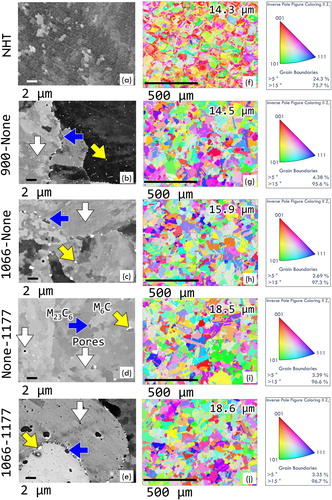
EDS analysis (see Section S3 of Supplemental Materials) revealed that the bulky precipitates residing mostly at the grain boundaries are rich in Cr, C and Mo—suggesting that they may be Cr-rich M23C6 carbide particles (blue arrows) [Citation13], while the finer precipitates in the grain interior are Mo-rich M6C carbides (yellow arrows). In the BSE micrographs, the Cr-rich carbides (blue arrows) appear in gray contrast, while the Mo-rich ones (yellow arrows) appear in bright contrast. The carbides preferentially exist at the grain boundaries and tend to grow with prolonged thermal exposure or at higher soaking temperature (compare Figures 1(a) with 1(b)–1(e)). Grain boundary carbides may hinder the grain growth of the L-PBF Hastelloy X during heat treatment. Indeed, from the inverse pole figure (IPF) maps shown in Figures 1(f)–1(j), it is evident that although the different heat treatments induced various extent of recrystallization, the grain size was not significantly altered. The mean equivalent circular grain diameter only increased from 14.3 μm in NHT condition to 18.6 μm in 1066–1177 condition.
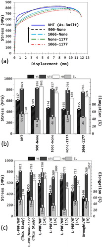
The engineering stress vs. displacement curves obtained during uniaxial tensile tests of L-PBF specimens in various heat treatment conditions are shown in Figure (a). In addition, the comparative bar charts of yield strength (YS), ultimate tensile strength (UTS), elongation to failure (EL), and nominal hardening rate (HR, calculated in this study as HR = (UTS-YS)/EL×100), for all the heat treatments in this study are compared in Figure (b). Tensile data in NHT and None-1177 conditions from this study were compared with similar heat treatment conditions from literature data for both the L-PBF and wrought counterparts in Figure (c). As shown in Figure (b), the NHT specimens exhibited the highest YS, while maintaining excellent UTS and EL amongst all L-PBF specimens. Accordingly, the HR under the NHT condition is the lowest. Compared with the literature data (see Figure (c)), it appears that the L-PBF properties, with the YS being the most significant, under the NHT condition in this work are superior [Citation9,Citation14,Citation15]. This is especially remarkable since the tensile tests in this study have been performed in the as-built surface condition, while the wrought data in literature were reported in the machined surface condition. It is also worth mentioning that with the increasing heat treatment temperature and/or soaking time, the YS successively reduces, while the HR increases to various extents.
Figure 2. Tensile test results for L-PBF Hastelloy X superalloy in various heat treatments: (a) engineering stress - displacement curves and (b) the corresponding column charts for YS, UTS, HR and EL. Selected data from (b) is compared with L-PBF as well as wrought data from literature in (c).
4. Discussion
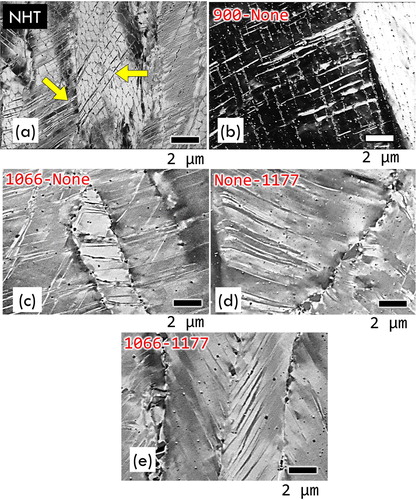
The superior YS in the NHT condition can be ascribed to the dendritic microstructure induced during the L-PBF process, with the inter-dendritic regions serving as the barriers for plastic deformation. The effect of dendritic microstructure on the plastic deformation has been revealed by focused ion beam (FIB) imaging performed on the longitudinal polished sections (i.e. x-z plane parallel to the build direction, as shown in Figure S1) of the failed tensile specimens (Figure ). The FIB images revealed the parallel as well as intersecting ‘deformation bands’ that oriented, on average, ∼45o relative to the loading direction (vertical direction in Figure ). As shown in Figure (a) by yellow arrows, the ‘deformation bands’ are interrupted by the inter-dendritic regions in the NHT microstructure (yellow arrows). With the gradual break down of the dendritic microstructure due to thermal exposure during heat treatments, the blocking effect reduces and, as a result, longer deformation bands form (see Figures 3(b)–(c)).
Figure 3. Micrographs obtained by FIB imaging on longitudinal (x-z plane) polished sections of failed tensile specimens (about 500 μm below line of fracture on surface), showing morphologies of deformation bands as affected by the microstructure resulting from various heat treatments.
FIB imaging relies on the interaction between the Ga+ ions with solid matter to induce secondary electrons and, therefore, the contrast in FIB imaging mode is primarily caused by differences in lattice orientation, lattice type, and composition [Citation16]. This could reasonably imply that the ‘deformation bands’ observed in Figure are due to deformation twinning instead of slip. Indeed, EBSD analyses performed on the polished longitudinal sections of the fractured specimens revealed strong misorientations between the bands and the matrix (see Figure (a)). Specifically, the matrix and bands formed a twinned orientation relation, with the twin planes being {111} planes and the twinning direction being <112>. Following Thompson's convention [Citation17] (see Figure S5 and Table S1 in Supplement Materials Section S5), the twin plane coincides with the plane ACD of the matrix and the twin, the twinning direction is along Aβtwin or Dβmatrix, (see Figures 4(b)).
Figure 4. (a) A typical IPF map of ‘deformation bands’ in the failed tensile specimen heat-treated under the 1066-None condition obtained by the EBSD scan on the longitudinal (x-z) plane. The Thompson’s tetrahedra shown in (b) and (c) illustrates the orientations of individual domains. The colors in the IPF maps, as indexed by the legend, indicate the crystallographic orientation along the normal direction (also the build direction z). (d) and (e) show the misorientation angle profiles along the solid lines in the ‘b’ and ‘c’ boxes in (a), respectively.
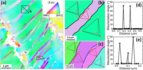
It is also notable that the twins do not share exactly the same orientation, as indicated by various shades of purple color in Figure (a). For instance, (see Figure (c)), a high-angle boundary with a misorientation angle of ∼20° exists between the two adjacent twins; which could be attributed to the sequential nature of the twins’ formation, i.e. some twins may form earlier and have dislocations with similar signs deposited on the twin boundaries before the formation of other twins. The deposited dislocations on the twin boundaries cause either a slight deviation in the twin-matrix orientation relation or a misorientation between two adjacent twins when they later join.
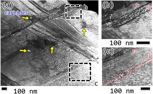
This speculation is confirmed by scanning transmission electron microscopy (STEM) on the fractured tensile specimens. As shown in Figure , twin bands appear in both bright and dark contrasts when they are parallel or oblique to the viewing axis, respectively. It is evident that certain twin bands, such as T1-T3 shown in Figures 5(b) and 5(c), have boundaries with dark contrast, which indicate the existence of boundary dislocations. In fact, one of such boundaries exists between the T1 and T2 twins, indicating that they are misoriented, similar to the configuration shown in Figure (c). Interestingly, the boundaries encasing the twin T4 lacks the boundary dislocations, suggesting that T4 was perhaps the latest to form. To sum, the ‘deformation bands’ observed in Figure are indeed ‘twin bands’ formed at different stages of deformation history for both heat-treated and NHT specimens. Although the ‘deformation twinning’ has not yet been reported for Hastelloy X at room temperature, it is not uncommon for FCC materials with low stacking fault energies (SFE) such as the twinning-induced plasticity (TWIP) steels with SFE below ∼30 mJ/m2 [Citation18]. Since essentially all alloying elements added to Ni (SFE = ∼120 mJ/m2) tend to substantially reduce the SFE [Citation19], Hastelloy X, a Ni-based alloy containing up to ∼50% of alloying elements, is expected to have a low SFE and experience ‘deformation twinning’.
Figure 5. Bright field STEM micrographs revealing the details of twin bands. Lamella was lift out from a 900-None specimen. Imaging condition: 30 kV and 120 pA.
Contrary to the monotonic decrease of YS with the gradual removal of as-solidified dendritic microstructure (upon heat treatment of specimens), Figure (a) also indicates that the EL and HR follow different trends. The HR for the NHT condition appears to be significantly lower than all the heat-treated conditions, while its ductility is higher than the heat-treated conditions where the dendrites are almost completely dissolved (Figure (b)). The substantially lower HR of the as-solidified specimens can be ascribed to the short dislocation mean free paths (MFP) limited by the dendritic microstructure. The small volume of each dendrite severely limits the interaction among dislocations, especially those from different slip planes. This limitation of MFP is not to be confused with that restricted by precipitates, in which case multiplication of dislocations can be promoted by Frank-Read mechanism leading to potentially high strain hardening rates, which is not the case under the NHT condition. As discussed in Section 3, strong chemical gradients exist between the inter-dendritic and dendrite interior regions. This, together with the dense dislocations collocated at these regions, poses strong barriers to both dislocations’ motion and deformation twinning. As a result, dislocation interactions among different slip systems are restricted, thus limiting the HR.
The NHT specimens’ good ductility, on the other hand, could be attributed to both inter-dendritic cellular structure's ability to hinder and delocalize plastic deformation as well as the lack of large grain boundary carbides that may act as fracture initiating sites. Specifically, since the inter-dendritic regions limit the dislocations’ motion and the length of twin bands, they can therefore alleviate the strain localization and serve to homogenize the distribution of plastic deformation. The blocking effect of inter-dendritic regions on slip or twin transmission is somewhat similar to that of the grain boundaries (GBs) in wrought Hastelloy X as revealed by Abuzaid et al. [Citation20]. The residual Burgers vectors for the inter-dendritic regions may arise from three origins: misorientation angle, chemical gradient, and the collocated dense dislocation network. While the former is expected to be weaker than that of GBs (the intra-granular misorientation angles are generally small in the NHT specimens), the latter two are expected to majorly contribute to the resistance to slip/twin transmission.
This apparent deviation from the conventional strength-ductility trade-off is akin to mechanisms observed for ultrafine grained materials [Citation21] except for the absence of grain boundary sliding in the NHT Hastelloy X. The significantly more homogenized distribution of plastic strain by the NHT dendritic microstructure is evident by comparing Figure (a) with Figures 3(b)–3(e) and noting that the twin bands are higher in number density, finer and shorter in the NHT condition compared to heat-treated conditions. The inter-dendritic cellular regions’ effect on the dislocation slip is expected to be similar, even though the distribution of dislocations over a large area is more challenging to characterize. In addition, the less grain boundary carbides in NHT specimens compared to other conditions is likely to delay, if not eliminate, the grain boundary fracture (discussed in Section S4 of the Supplemental Materials). Indeed, the fractography images (Figure S4(a) and S4(d)) of the fractured NHT specimens reveal very little grain boundary fracture compared to other conditions. Larger dimples on the fracture surfaces are also commensurate with the good ductility of the NHT specimens.
In contrast, the 900-None condition has shown the highest HR. This could be attributed to the fact that the 900-None treatment partially broke down the 3D network of the inter-dendritic regions and left isolated Mo-rich (M6C) carbides (∼100 nm in size and ∼3 μm in spacing, as indicated by the yellow arrow in Figure (b)). These carbides can significantly promote the dislocations’ multiplication, resulting in an increased HR. As shown in Figure , the dislocation density near these particles (yellow arrows) is significantly higher than in the matrix, as reflected by the dark contrast in the bright field STEM micrograph. The larger size as well as higher number density of carbides, while acting as dislocation barriers and contributing to the pronounced strain hardening behavior, can also limit the ductility. Indeed, the fracture surfaces of the 900-None specimens revealed the existence of carbides in all the dimples (see Figure S4(g) in the Supplement Materials Section S4).
Thermal exposure at higher temperatures and longer soaking time (e.g., the 1066–1177 condition compared to 900-None or 1066-None condition) have significantly reduced the number density of the carbide particles (see Figures 1(b)–1(e)) in the grain interior and, therefore, reduced the strain hardening rate and improved the ductility. Comparing Figure S4(g) with Figure S4(i), the larger dimple size on the fracture surface of the None-1177 specimen compared to the 900-None specimen is notable. Due to the much longer dislocation MFP, the HR of all heat-treated specimens are higher than the NHT ones (see Figure (b)).
5. Summary
This study reports superior room temperature tensile properties of as-fabricated (both in microstructure and surface condition) L-PBF Hastelloy X relative to the wrought counterparts. The simultaneous retainment of strength and ductility in the as-fabricated, non-heat-treated condition is anomalous in L-PBF Ni-based superalloys. Characterization of tensile behavior as a function of a range of microstructures, from fully dendritic to fully solutionized, revealed that the as-solidified, fine dendritic microstructure was responsible for the superiority of the L-PBF Hastelloy X over wrought. In addition, a twinning based monotonic deformation mechanism, not well known for Hastelloy XFootnote1 at room temperature, was discovered and characterized in all heat-treated and non-heat-treated conditions.
Supplemental Material
Download MS Word (2.9 MB)Acknowledgement
This paper is based upon the work partially funded by the National Aeronautics and Space Administration (NASA) under Award #80MSFC19C0010.
Disclosure statement
No potential conflict of interest was reported by the author(s).
Additional information
Funding
Notes
1 While this manuscript was under review, the authors became aware of the recent publication (available online Jan 22, 2021) of a related work also reporting the deformation twinning in L-PBF Hastelloy X (See Ref. [Citation22]).
References
- Thompson SM, Bian L, Shamsaei N, et al. An overview of Direct Laser Deposition for additive manufacturing; part I: transport phenomena, modeling and diagnostics. Addit Manuf. 2015;8:36–62.
- Shamsaei N, Yadollahi A, Bian L, et al. An overview of direct laser deposition for additive manufacturing; part II: mechanical behavior, process parameter optimization and control. Addit Manuf . 2015;8:12–35.
- Dudzinski D, Devillez A, Moufki A, et al. A review of developments towards dry and high speed machining of Inconel 718 alloy. Int J Mach Tools Manuf. 2004;44:439–456.
- Marchese G, Lorusso M, Parizia S, et al. Influence of heat treatments on microstructure evolution and mechanical properties of Inconel 625 processed by laser powder bed fusion. Mater Sci Eng A. 2018;729:64–75.
- Gallmeyer TG, Moorthy S, Kappes BB, et al. Knowledge of process-structure-property relationships to engineer better heat treatments for laser powder bed fusion additive manufactured Inconel 718. Addit Manuf. 2020;31:100977.
- Kanagarajah P, Brenne F, Niendorf T, et al. Inconel 939 processed by selective laser melting: effect of microstructure and temperature on the mechanical properties under static and cyclic loading. Mater Sci Eng A. 2013;588:188–195.
- Kreitcberg A, Inaekyan K, Turenne S, et al. Temperature- and time-dependent mechanical behavior of post-treated IN625 alloy processed by laser powder Bed fusion. J Manuf Mater Process. 2019;3:75.
- Donachie MJ, Donachie SJ. Superalloys: a technical guide. Materials Park (OH): ASM international; 2002.
- Haynes Internatioal Website. Hastelloy X: Tensile Properties.
- ASTM International. ASTM B822-20: Standard Test Method for Particle Size Distribution of Metal Powders and Related Compounds by Light Scattering. 2020.
- ASTM International. ASTM e8/E8M-16: standard test methods for tension testing of metallic materials. West Conshohocken (PA): ASTM International. 2016.
- Wang H, Chen L, Dovgyy B, et al. Micro-cracking, microstructure and mechanical properties of Hastelloy-X alloy printed by laser powder bed fusion: As-built, annealed and hot-isostatic pressed. Addit Manuf. 2021;39:101853.
- Zhao JC, Larsen M, Ravikumar V. Phase precipitation and time-temperature-transformation diagram of Hastelloy X. Mater Sci Eng A. 2000; 293: 112–119.
- Tomus D, Tian Y, Rometsch PA, et al. Influence of post heat treatments on anisotropy of mechanical behaviour and microstructure of Hastelloy-X parts produced by selective laser melting. Mater Sci Eng A. 2016;667:42–53.
- Sanchez-Mata O, Muñiz-Lerma JA, Wang X, et al. Microstructure and mechanical properties at room and elevated temperature of crack-free Hastelloy X fabricated by laser powder bed fusion. Mater Sci Eng A. 2020;780:139177.
- Volkert CA, Minor AM. Focused Ion Beam Micromachining. MRS Bull. 2007;32:389–399.
- Hirth JP, Lothe J. Theory of dislocations. 2nd ed. Malabar (FL): Krieger Publishing Company. 1982.
- Kim J, Lee S-J, De Cooman BC. Effect of Al on the stacking fault energy of Fe–18Mn–0.6C twinning-induced plasticity. Scr Mater. 2011;65:363–366.
- Dodaran MS, Guo S, Khonsari MM, et al. A theoretical calculation of stacking fault energy of Ni alloys: The effects of temperature and composition. Comput Mater Sci. 2021;191:110326.
- Abuzaid WZ, Sangid MD, Carroll JD, et al. Slip transfer and plastic strain accumulation across grain boundaries in Hastelloy X. J Mech Phys Solids. 2012;60:1201–1220.
- Meyers MA, Mishra A, Benson DJ. Mechanical properties of nanocrystalline materials. Prog Mater Sci. 2006;51:427–556.
- Sanchez-Mata O, Wang X, Muñiz-Lerma JA, et al. Dependence of mechanical properties on crystallographic orientation in nickel-based superalloy Hastelloy X fabricated by laser powder bed fusion. J Alloys Compd. 2021;865:158868.