
 ?Mathematical formulae have been encoded as MathML and are displayed in this HTML version using MathJax in order to improve their display. Uncheck the box to turn MathJax off. This feature requires Javascript. Click on a formula to zoom.
Abstract
Nanoporous gold (NPG) provides a model material for studying small-scale deformation and the mechanical behavior of network solids. We report a transmission electron microscopy study of the defect structure in electron-transparent NPG leaf deformed by rolling. The results confirm that plastic deformation significantly enhances the defect density. Specifically, twins are formed on several sets of crystallographic planes, and their interaction forms Lomer-Cottrell locks. This inhibits dislocation escaping from NPG, thus avoiding the dislocation starvation scenario that is often considered in the ‘smaller is stronger' context of small-scale plasticity. Instead, strain hardening is apparently linked to accumulation and interaction of twins.
GRAPHICAL ABSTRACT

IMPACT STATEMENT
This paper provides a direct observation of the lattice defects in plastically deformed nanoporous gold, confirming the contribution of accumulation and interaction of defects to the strain hardening rate.
1. Introduction
Nanoporous gold (NPG) prepared via dealloying consists of interconnected nanoscale struts or ‘ligaments' with narrow size distribution [Citation1]. The size- and interface effects arising from its nanoscale structure endow it with the mechanical properties of nano-objects [Citation2,Citation3]. These properties are maintained even when NPG samples are scaled to millimeter size, enabling studies of materials mechanical behavior by robust macroscopic testing schemes [Citation4]. NPG is therefore studied as a model system for small-scale plasticity [Citation5,Citation6]. As compared to idealized scenarios with uniform and uniaxial stress states, the complex microstructural morphology of porous solids such as NPG results in multiaxial stress states [Citation7–10]. Such states are relevant, since they are representative for the mechanics of real materials or of engineering parts at any scale.
Compression tests on NPG invariably show a high strain hardening rate [Citation11–13]. Strain hardening is essential for maintaining stable plastic deformation of NPG, and can provide a signature of fundamental deformation mechanisms in the material. Previously, dislocation starvation has been confirmed in gold nanopillars under compression [Citation14]. If that notion were transferred to NPG, one would expect the material’s strain hardening mainly arise from densification during plastic compression. It is well established that the flow stress of porous materials increases with density [Citation15]. However, finite element modeling suggests that densification of NPG alone cannot account for the experimental observation [Citation7]. This implies dislocation accumulation and, indeed, atomistic simulations confirm that scenario [Citation16,Citation17]. Those studies suggest that accumulation and reaction of planar defects persist and contribute to the strain hardening rate, even when the ligament sizes are only 2∼3 nm. Nevertheless, the results from the atomistic studies must be taken with a grain of salt, because they are inevitably based on unrealistically high deformation rates. Therefore, atomic-scale experimental studies are required for clarifying the deformation mechanism in NPG.
Transmission electron microscopy (TEM) may be considered the method of choice for direct observation of lattice defects. However, defects can be inherited from the master alloy [Citation18] or originate from dealloying [Citation19] or from TEM lamella preparation [Citation20]. It is typically challenging to distinguish these defects from those induced by deformation. Artefacts from TEM preparation can be avoided by working with electron-transparent samples, such as nanoporous nanowires [Citation21]. Such studies reveal planar defects after deformation. Yet, planar defects have also been reported in undeformed NPG [Citation19,Citation22]. A dedicated comparison between undeformed and deformed NPG under identical imaging conditions, including appropriate zone axis and magnification, remains to be presented. Thus the observations so far provide no conclusive evidence for deformation-induced defects or defect accumulation during deformation.
Dealloyed white gold leaf provides another approach to study NPG by TEM without thinning [Citation19,Citation23]. However, the homogeneous plastic deformation of NPG leaf is challenging and has not been demonstrated. The plastic instability and strain localization of NPG in tension [Citation24,Citation25] impair homogeneous tensile deformation. Furthermore, in-plane compression of thin-films induces buckling, again preventing homogeneous deformation.
A high-resolution (HR) TEM study [Citation22] observes the tensile deformation of individual ligaments of NPG leaf in situ. Dislocation nucleation and egression at surfaces are apparent, as is the generation and annihilation of planar faults by partial dislocations. The study provides no evidence for systematic defect accumulation or interaction that could be associated with strain hardening.
There remains a need for TEM studies to verify defect accumulation and interaction during the homogeneous deformation of NPG. Here, we demonstrate the deformation of NPG leaf in compression, and we report ex-situ TEM study of the density and distribution of defects within a large field of view in dark-field mode as well as the defect structure at atomic-scale in high-resolution mode, before and after each processing stage to trace the changes of defects in NPG.
2. Experiments
Au25Ag75 (at.%) leaves (6 carat, Eytzinger GmbH, Germany), ∼160 nm in thickness, were annealed in Ar at 600°C for 1 h followed by furnace cooling. The leaves were cut into 1010 mm2 patches and dealloyed (for 20 s at room temperature) by free corrosion in a 65 vol.% HNO3 solution, then repeatedly cleaned by deionized water and immersed in ethanol for 2 h. Subsequently, each patch was deposited on the surface of a polished, 1.5 mm thick aluminum plate and dried in air. A sandwich structure was generated by applying a second aluminum plate, and the sandwich was then rolled in multiple passes at room temperature. The thickness was reduced ∼0.1 mm per pass and the strain rate was ∼0.08 s−1 (see Supporting Information). Note that the deformation behavior of rolled NPG can represent the general deformation scenarios, since the local stress state of the ligaments is multiaxial even under macroscopically uniaxial deformation conditions [Citation7]. The sandwich was then etched in a 16 vol.% HCl solution, dissolving the aluminum plates and resulting in large pieces of rolled NPG leaf floating on the solution surface. These were again carefully cleaned.
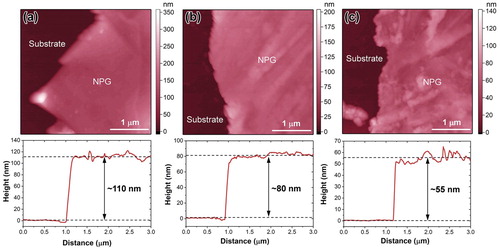
To measure the thickness variation, NPG leaves with and without rolling were applied on Si wafers and examined with atomic force microscopy (JPK Nano Wizard), see Figure . The thickness reduction was found as 27% and 50% after 2 and 4 rolling passes, respectively.
Figure 1. Atomic force microscopy (AFM) results of (a) as-dealloyed, (b) 27% plastically deformed and (c) 50% plastically deformed NPG leaves. Display regions include bare substrate and NPG leaf, imaged near edges of the leaves. Top row shows AFM images, bottom row shows representative height profiles across the edge.
To prepare TEM specimens, the leaves in various conditions were lifted from ethanol by Cu grids and dried at room temperature. All specimens were investigated using a FEI Talos F200X TEM at 200 kV.
3. Results and discussion
3.1. Master alloy
The microstructure of annealed master alloy is displayed in Figure . The overview micrograph (Figure (a)) shows several grains with grain sizes over 1 μm. Twins are observed in some grains, as indicated by arrows, but other grains appear free of twins. The selected area electron diffraction (SAED) pattern taken along [011] zone axis of the grain from the square region in Figure (a) is shown in Figure (c). Diffraction spots of twins are marked by dashed lines. The dark-field image of the same region (Figure (b)), achieved using (200) twin reflection, illustrates the existence of many twin lamellae.
Figure 2. Micrographs of the annealed master alloy. (a) Bright-field image. Grain boundaries (GBs) are indicated by arrows. (b) Dark-field image corresponding to the square region in (a) using (200) twin reflection in (c). (c) Selected area electron diffraction pattern corresponding to the grain in the square region of (a). Beam direction (BD) is parallel to [011] zone axis.
![Figure 2. Micrographs of the annealed master alloy. (a) Bright-field image. Grain boundaries (GBs) are indicated by arrows. (b) Dark-field image corresponding to the square region in (a) using (200) twin reflection in (c). (c) Selected area electron diffraction pattern corresponding to the grain in the square region of (a). Beam direction (BD) is parallel to [011] zone axis.](/cms/asset/9330b158-9196-464c-936f-1f8786dd4f9f/tmrl_a_1924305_f0002_oc.jpg)
Figure illustrates pre-existing twins, several hundred nanometers to several micrometers in length, in some grains of the annealed master alloy but not in others. In view of this heterogeneous microstructure, our presentation of the experimental results and discussion will distinguish between findings for grains with and without pre-existing twins.
3.2. As-dealloyed NPG
In as-dealloyed specimen, grain boundaries can be distinguished at low magnification, as indicated by arrows in the overview micrograph (Figure (a)). Further evidence of grain boundaries is shown in Figure S1 of the Supporting Information. The image at higher magnification (Figure (b)) shows that the as-dealloyed leaf consists of several layers of interconnected ligaments. A clearer view of nanoporous structure containing only one layer of ligaments near a hole of the leaf is shown in Figure S2, suggesting 8 nm as the average ligament diameter.
Figure 3. TEM images of as-dealloyed NPG. (a) Bright-field image at low magnification, showing evident grain boundaries (GBs). (b) High magnified image, revealing nanoporous structure. (c) Bright-field image and (d) selected area electron diffraction (SAED) pattern from a grain without pre-existing twins. (e) Bright-field image, (f-g) dark-field images and (h) SAED pattern of a grain containing pre-existing twins. The dark-field images are obtained using (200) twin reflection in (h), (g) is the magnification of the square region in (f). Higher magnified image of some tiny twins in (g) is inserted at the lower left. The beam direction (BD) for (c-h) is parallel to [011] zone axis and the diameter of the selected area for (d) and (h) is 800 nm.
![Figure 3. TEM images of as-dealloyed NPG. (a) Bright-field image at low magnification, showing evident grain boundaries (GBs). (b) High magnified image, revealing nanoporous structure. (c) Bright-field image and (d) selected area electron diffraction (SAED) pattern from a grain without pre-existing twins. (e) Bright-field image, (f-g) dark-field images and (h) SAED pattern of a grain containing pre-existing twins. The dark-field images are obtained using (200) twin reflection in (h), (g) is the magnification of the square region in (f). Higher magnified image of some tiny twins in (g) is inserted at the lower left. The beam direction (BD) for (c-h) is parallel to [011] zone axis and the diameter of the selected area for (d) and (h) is 800 nm.](/cms/asset/74e6cd13-28e1-4bdc-a5d9-f71c830fcf0d/tmrl_a_1924305_f0003_oc.jpg)
The bright-field image and SAED pattern of an area without pre-existing twins are shown in Figures (c,d). The SAED pattern reveals a single crystal structure over a large area (800 nm in diameter), indicating the grain structure of the master alloy remains, in accordance with previously reported ion channeling [Citation3], electron backscatter diffraction (EBSD) [Citation4] and X-ray diffraction results [Citation20]. Besides the large grain size, noteworthy is that the SAED of Figure (d) shows no signature of twins.
The TEM images for a region containing pre-existing twins are displayed in Figures (e–h). The twin reflections are marked by dashed lines in Figure (h). Figures (e,f) show sets of many twins aggregated along {111} planes; these aggregates form straight lines whose lengths range from several hundred nanometers to several micrometers. It appears obvious to associate these features with the pre-existing twin lamellae of the master alloy, see Figure . In other words, the aggregates reflect microstructural features of the master alloy and not new twins generated during dealloying.
Besides the twin aggregates, there are also tiny isolated twins. Upon close inspection, examples of isolated twins can be seen (near the arrows) in Figure (g), which is a magnification of the square region delineated in Figure (f). These twins only appear in part of the matrix. Further magnification of some tiny twins is inserted in Figure (g). We speculate that the tiny twins may be generated by spontaneous plastic shear in response to large surface-induced shear stresses during dealloying [Citation19,Citation26]. Irrespective of their origin, there are only very few isolated twins in as-dealloyed specimen. This is most notably supported by the absence of twin reflections in the SAED pattern (Figure (d)) and by the extended, featureless regions in the dark-field images (Figures (f,g)).
The observations in Figure suggest the twins in as-dealloyed specimen mainly reflect pre-existing twins in the master alloy. Since most grains exhibit few pre-existing twins, we conclude that the density of twins in as-dealloyed NPG prepared from annealed master alloy is low. This notion is supported by the X-ray diffraction results [Citation27].
3.3. Deformed NPG
After 27% rolling, grain boundaries are still observed in NPG at low magnification, as marked by arrows in Figure (a). The inserted image at high magnification shows that the nanoporous structure is retained. Figures (b–d) refer to a region without the twin aggregates that we identified as pre-existing twins. Note that the image magnification and aperture size for SAED pattern are identical to Figures (c,d). The primary diffraction spots from the matrix in the SAED pattern of Figure (b) are segments of arcs, indicating a mosaic spread of the local orientations in the deformed specimen, yet with a memory of the original crystallographically coherent structure. This is in good agreement with EBSD maps of deformed NPG [Citation4]. These authors associated the misorientation with the accumulation of ‘pore-channel' dislocations in pore space [Citation4].
Figure 4. TEM images of the 27% cold-rolled NPG. (a) Bright-field image at low magnification. Inserted image reveals the nanoporous structure. (b) Selected area electron diffraction (SAED) pattern, (c) bright-field image and (d) dark-field image from a grain without pre-existing twins. (e) Bright-field and (f) dark-field images of a grain containing pre-existing twins. (g) Bright-field and (h) dark-field images of an area without pre-existing twins at high magnification. Beam directions (BDs) for (b-h) are parallel to [011] zone axis and all dark-field images are achieved using the reflections highlighted by the circles marked in corresponding SAED patterns. The selected areas for all SAED patterns are 800 nm in diameter.
![Figure 4. TEM images of the 27% cold-rolled NPG. (a) Bright-field image at low magnification. Inserted image reveals the nanoporous structure. (b) Selected area electron diffraction (SAED) pattern, (c) bright-field image and (d) dark-field image from a grain without pre-existing twins. (e) Bright-field and (f) dark-field images of a grain containing pre-existing twins. (g) Bright-field and (h) dark-field images of an area without pre-existing twins at high magnification. Beam directions (BDs) for (b-h) are parallel to [011] zone axis and all dark-field images are achieved using the reflections highlighted by the circles marked in corresponding SAED patterns. The selected areas for all SAED patterns are 800 nm in diameter.](/cms/asset/c58f94c6-8b6a-4e0e-a529-afcd609c6a02/tmrl_a_1924305_f0004_oc.jpg)
Besides the arc primary diffraction spots, weak streaks from twins along [11] and [
1
] directions are observed in Figure (b). The twin streaks parallel to [11
] direction are marked by dashed lines and the twin streaks along [
1
] direction are indicated by arrows. The appearance of streaks implies that most of the twins are only few atomic layers thin. The dark-field image (Figure (d)) obtained using (
1
) twin reflection reveals many randomly distributed twins. Importantly, the morphology, density and distribution of these twins have no analogy with those in as-dealloyed specimen. This implies that these twins must originate from plastic deformation.
The above-mentioned deformation twins are short and thin, hence their volume fraction is low even though their number density is high. This notion is consistent with the weak streaks in the SAED pattern.
The emergence of twin steaks along both [11] and [
1
] directions in Figure (b) suggests that different slip systems have been activated during deformation. As there are four {111} twin planes in face-centered cubic structured gold, the net density of all deformation twins must be even higher than that observed in our dark-field image.
An area with pre-existing twins is displayed in Figures (e,f). The twin aggregates of as-dealloyed material are no longer recognizable in the bright-field image (Figure (e)) of the deformed material. Yet, these features remain in the dark-field image (Figure (f)), where they can be identified by their alignment with the (11) twin plane. Many deformation twins are also seen, featuring a random arrangement in the matrix.
The magnified images of an area without pre-existing twins are shown in Figures (g,h), demonstrating the homogenous distribution of deformation twins in ligaments.
Further reduction of thickness (50%) for NPG leaf results in cold-welding of ligaments and the formation of diffraction rings (Figure S3).
Figure verifies the accumulation of massive deformation twins on different crystallographic planes in NPG. It is then natural to suspect that twins can interact. That notion is indeed supported by HRTEM images, as will now be discussed.
3.4. High-resolution imaging
In the present work, the interaction of planar defects is frequently observed in the deformed specimen. Figure (a) shows the typical microstructure of 27% rolled NPG leaf near a crack at high magnification. The micrograph reveals an abundance of planar defects parallel to (11) and (
1
) planes, as indicated by arrows. The HRTEM image of region B is shown in Figure (b), where a stacking fault (labeled SF) on (11
) plane interacts with a twin on (
1
) plane. Instead of traversing the ligament, the Shockley partial dislocation associated with the stacking fault was arrested inside the ligament, since the twin boundary (labeled TB) acts as a barrier.
Figure 5. (a) TEM image of 27% cold-rolled NPG at high magnification, showing planar defects on different planes. (b) High-resolution TEM image corresponding to region B in (a), revealing the pile up of Shockley partial dislocation associated with a stacking fault (SF) on the twin boundary (TB). (c) High-resolution TEM image corresponding to region C in (a), showing a Lomer-Cottrell (L-C) lock. The magnified Lomer-Cottrell dislocation core is inserted in (c). (d) Schematic illustration of deformation mechanism in NPG.
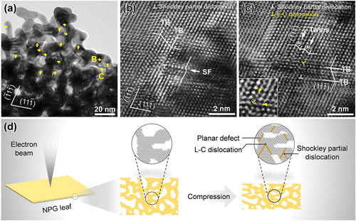
Besides the deformation-induced planar faults, Figure (c) reveals the formation of a Lomer-Cottrell (labeled L-C) lock, where twin lamellae on (1
) plane and a twin on (11
) plane are observed. The reaction of leading partial dislocations slipping on different planes results in a Lomer-Cottrell dislocation at the intersection, as marked with yellow ‘T' and magnified in the inserted image of Figure (c). Indeed, Lomer-Cottrell locks are observed in many places of the deformed NPG.
Step edges and corner lines at the free surface of nano-objects are decorated by local strains and stress concentrations that make these surface features preferred sites for dislocation nucleation [Citation28,Citation29]. Shockley partial dislocations are common in gold due to the metal’s low stacking fault energy, and the nucleation at the surface may therefore produce these defects preferentially [Citation30]. Partial dislocations are also favored over full ones in small structures [Citation31]. After traveling small distances, the partial dislocations without interaction may escape from nanopillars, leaving behind stacking faults or deformation twins. As one scenario under consideration, the subsequent deformation leads to the emission and propagation of trailing partial dislocation on the same slip plane, resulting in annihilation of dislocations and planar defects at free surface of gold nanopillars [Citation14,Citation32]. When the dislocation generation rate balances the dislocation annihilation rate, the condition of dislocation starvation applies.
In NPG, the deformation induced defects are schematically illustrated in Figure (d). In contrast to the dislocation starvation scenario in nanopillars, the result reveals the accumulation and interaction of planar defects on different crystallographic planes in NPG. Many step edges at the surface of NPG – partly geometrically necessary because of the material’s high surface curvature – provide massive nucleation sites for dislocations [Citation16,Citation33]. Furthermore, the local stress state of NPG is generally multiaxial due to the local bending deformation of the ligaments [Citation7–10]. The multiaxial stress field promotes the nucleation of (partial-) dislocations on more than one slip system [Citation16,Citation17]. One thus expects stacking faults or twins on different slip planes and, consequently, the interference or reaction between planar defects. Figures (b,c) confirm this expectation and support the experimental finding of the gradual emergence of a strain rate dependence as NPG is deformed [Citation4].
The interaction of planar defects, especially the formation of Lomer-Cottrell locks, can efficiently stabilize lattice defects [Citation32], prohibiting the possible escape of dislocations during subsequent plastic deformation. That scenario further enhances the accumulation of lattice defects and also promotes strain hardening. In this respect, our observations provide strong experimental support for the modeling studies that suggest strain hardening as part of the constitutive plastic deformation behavior of NPG. Furthermore, our observations support the defect accumulation that is seen in atomistic deformation studies of NPG. We also note that the stable Lomer-Cottrell locks would act as internal sources for dislocations, further enhancing the strain hardening ability.
4. Summary
NPG with complex stress states and geometric boundary conditions acts as a model system for small-scale plasticity in real nanomaterials. In this work, a uniform deformation was applied to electron-transparent NPG leaf, in which NPG leaf was sandwiched by aluminum plates and then subjected to properly controlled rolling. The results confirm the accumulation of lattice defects that has been predicted based on experimental strain hardening data and atomistic simulation. Contrary to the dislocation starvation model of small-scale plasticity, the density of twins on different crystallographic planes is significantly enhanced by plastic deformation. The reaction between twins leads to the formation of Lomer-Cottrell locks and thus inhibits the egression of dislocations at surfaces. Defect accumulation and strain hardening effectively enhance the mechanical stability and reliability of NPG.
Supplemental Material
Download PDF (3.5 MB)Acknowledgements
Support by Deutsche Forschungsgemeinschaft, Projektnummer 192346071 – SFB 986, and assistance by Manuel Brinker with AFM imaging are acknowledged. M.L. acknowledges support from the Sino-German (CSC-DAAD) Postdoc Scholarship Program.
Disclosure statement
No potential conflict of interest is reported by the authors.
References
- Erlebacher J, Aziz MJ, Karma A, et al. Evolution of nanoporosity in dealloying. Nature. 2001;410:450–453.
- Farkas D, Caro A, Bringa E, et al. Mechanical response of nanoporous gold. Acta Mater. 2013;61:3249–3256.
- Volkert CA, Lilleodden ET, Kramer D, et al. Approaching the theoretical strength in nanoporous Au. Appl Phys Lett. 2006;89, 061920.
- Jin H, Kurmanaeva L, Schmauch J, et al. Deforming nanoporous metal: role of lattice coherency. Acta Mater. 2009;57:2665–2672.
- Mameka N, Wang K, Markmann J, et al. Nanoporous gold — testing macro-scale samples to probe small-scale mechanical behavior. Mater Res Lett. 2016;4:27–36.
- Biener J, Hodge AM, Hamza AV. Deformation behavior of nanoporous metals. In: Yang F, Li JC-M, editor. Micro nano mech test Mater devices. Boston, MA: Springer; 2008. p. 118–135.
- Huber N, Viswanath RN, Mameka N, et al. Scaling laws of nanoporous metals under uniaxial compression. Acta Mater. 2014;67:252–265.
- Hsieh M-T, Endo B, Zhang Y, et al. The mechanical response of cellular materials with spinodal topologies. J Mech Phys Solids. 2019;125:401–419.
- Richert C, Huber N. Skeletonization, geometrical analysis, and finite element modeling of nanoporous gold based on 3D tomography data. Metals. 2018;8,282.
- Mangipudi KR, Epler E, Volkert CA. On the multiaxial yielding and hardness to yield stress relation of nanoporous gold. Scr Mater. 2018;146:150–153.
- Jin H-J, Weissmüller J. A material with electrically tunable strength and flow stress. Science. 2011;332:1179–1182.
- Wu Y, Markmann J, Lilleodden ET. Electro-chemo-mechanical coupling of nanoporous gold at the microscale. Appl Phys Lett. 2019;115, 251602.
- Ye X, Liu L, Jin H. Responsive nanoporous metals: recoverable modulations on strength and shape by watering. Nanotechnology. 2016;27, 325501.
- Greer JR, Oliver WC, Nix WD. Size dependence of mechanical properties of gold at the micron scale in the absence of strain gradients. Acta Mater. 2005;53:1821–1830.
- Gibson LJ, Ashby MF. The mechanics of three-dimensional cellular materials. Proc R Soc London A. 1982;382:43–59.
- Ngô B-ND, Stukowski A, Mameka N, et al. Anomalous compliance and early yielding of nanoporous gold. Acta Mater. 2015;93:144–155.
- Ruestes CJ, Farkas D, Caro A, et al. Hardening under compression in Au foams. Acta Mater. 2016;108:1–7.
- Gwak E, Jeon H, Song E, et al. Twinned nanoporous gold with enhanced tensile strength. Acta Mater. 2018;155:253–261.
- Parida S, Kramer D, Volkert CA, et al. Volume change during the formation of nanoporous gold by dealloying. Phys Rev Lett. 2006;97, 035504.
- Petegem SV, Brandstetter S, Maass R, et al. On the microstructure of nanoporous gold: An X-ray diffraction study. Nano Lett. 2009;9:1158–1163.
- Dou R, Derby B. Deformation mechanisms in gold nanowires and nanoporous gold. Philos Mag. 2011;91:1070–1083.
- Liu P, Wei X, Song S, et al. Time-resolved atomic-scale observations of deformation and fracture of nanoporous gold under tension. Acta Mater. 2019;165:99–108.
- Ding Y, Kim Y, Erlebacher J. Nanoporous gold leaf: “ancient technology”/advanced material. Adv Mater. 2004;16:1897–1900.
- Biener J, Hodge AM, Hamza A V. Microscopic failure behavior of nanoporous gold. Appl Phys Lett. 2005;87,121908.
- Wang K, Kobler A, Kübel C, et al. Nanoporous-gold-based composites: toward tensile ductility. NPG Asia Mater. 2015;7,e187.
- Crowson DA, Farkas D, Corcoran SG. Mechanical stability of nanoporous metals with small ligament sizes. Scr Mater. 2009;61:497–499.
- Graf M, Ngô BD, Weissmüller J, et al. X-ray studies of nanoporous gold: powder diffraction by large crystals with small holes. Phys Rev Mater. 2017;076003:1–13.
- Diao J, Gall K, Dunn ML. Yield strength asymmetry in metal nanowires. Nano Lett. 2004;4:1863–1867.
- Roy A, Kundu S, Müller K, et al. Wrinkling of atomic planes in ultrathin Au nanowires. Nano Lett. 2014;14:4859−4866.
- Diao J, Gall K, Dunn ML, et al. Atomistic simulations of the yielding of gold nanowires. Acta Mater. 2006;54:643–653.
- Yue Y, Liu P, Deng Q, et al. Quantitative evidence of crossover toward partial dislocation mediated plasticity in copper single crystalline nanowires. Nano Lett. 2012;12:4045–4049.
- Afanasyev KA, Sansoz F. Strengthening in gold nanopillars with nanoscale twins. Nano Lett. 2007;7:2056–2062.
- Fujita T, Guan P, McKenna K, et al. Atomic origins of the high catalytic activity of nanoporous gold. Nat Mater. 2012;11:775–780.