
 ?Mathematical formulae have been encoded as MathML and are displayed in this HTML version using MathJax in order to improve their display. Uncheck the box to turn MathJax off. This feature requires Javascript. Click on a formula to zoom.
Abstract
Kink-band strengthening was first quantitatively evaluated using an Mg–Zn–Y single crystal containing long-period stacking ordered (LPSO) nanoplates. The ability of a kink-band boundary to act as a barrier that hinders the motion of dislocations is high and comparable to that of a general random grain boundary. Nevertheless, a kink-band boundary is regarded as a simple tilt boundary in the dislocation model. One reason for the anomalous ability of kink-band boundary acting as barriers is related to its peculiar hierarchical structure, in which many small kink bands with high crystal rotation angles accumulate in a localized region.
GRAPHICAL ABSTRACT

IMPACT STATEMENT
By the quantitative estimation using the single crystal, the origin of the anomalous ability of kink bands acting as barriers that hinder the motion of dislocation was elucidated.
1. Introduction
Recently, the strengthening of Mg alloys using kink bands has been the focus of researchers, especially in the Mg–Zn–Y alloy system containing the long-period stacking ordered (LPSO) phase [Citation1–15]. A kink band is a deformation band induced by the rearrangement of dislocations along a direction perpendicular to the slip plane [Citation16,Citation17]. The LPSO crystal structure is constructed by the alternating stacking of Mg and concentrated Zn/Y layers in which the Zn/Y atoms form an L12-like cluster [Citation18]. Thus, the LPSO crystal structure prevents the motion of dislocations across the Zn/Y layers, i.e. non-basal slips and deformation twins, and restricts the motion only along the direction parallel to the stacking plane (basal plane) [Citation19–21]. In this situation, kink bands are formed when stress is applied along the direction parallel to the basal plane, as shown in Supplementary Fig. S1 [Citation16,Citation19–21]. The strengthening of an LPSO-phase alloy by kink bands, i.e. kink-band strengthening, is known to effectively occur in extruded alloys [Citation22,Citation23]. However, a quantitative analysis of kink-band strengthening has not been carried out, i.e. the relationships between the distribution distance of the kink-band boundary, the rotation angle, and the increase in strength, have not been precisely clarified yet because of the complicated and refined microstructures of the extruded alloys.
Recently, we found the induction of kink-band formation in an Mg–Zn–Y single crystal via the dispersion of LPSO nanoplates [Citation24]. An LPSO nanoplate comprises a Zn/Y concentrated stacking fault and its aggregates. We found that LPSO nanoplates sufficiently prevent the motion of dislocations across them, i.e. the operation of a deformation mode other than the basal slip, as well as that in the LPSO phase. Consequently, the formation of kink bands is induced [Citation24].
In this study, the effects of kink-band strengthening were first quantitatively evaluated using an Mg–Zn–Y single crystal containing LPSO nanoplates. The ability of a kink-band boundary to act as a barrier that prevents the motion of dislocations compared to that of a general grain boundary was examined by double compression tests combined with a Hall–Petch analysis of the kink-band boundaries.
2. Experimental procedure
A master ingot with a composition of Mg–0.2 at% Zn–0.6 at% Y was prepared by induction melting in a carbon crucible. Directional solidification (DS) was conducted using the Bridgman technique in an Ar-gas atmosphere at a growth rate of 5.0 mm/h. A detailed analysis of the resulting single crystal was presented in our previous paper [Citation24]. Using this single crystal, ‘double compression tests’ were conducted. First, a rectangular specimen (approximately 2 mm × 7 mm × 7 mm) with a loading orientation parallel to [110] was prepared. Then, a rectangular notch with dimensions of ∼ 2 mm × 1 mm × 3 mm was introduced on the side surface of the specimen to induce the formation of kink bands during compressive deformation, as described in detail later. The prepared specimen was compressed up to 5% plastic strain at room temperature (RT); this is called the ‘first deformation (predeformation)' or ‘0° deformation' hereafter. Then, a second compression specimen with a [1 1
1.85] loading axis, which is inclined 45° from [0001], and dimensions of ∼ 2 mm × 2 mm × 5 mm was cut from the deformed specimen, and the specimen was again compressed. This is called the ‘second deformation' or ‘45° deformation'. The Schmid factor for (0001) <11
0> basal slip is 0 and 0.5 for 0° and 45° deformation, respectively. Thus, the formation of kink bands and the motion of basal dislocations across the kink bands are expected for the first and second deformation, respectively. The Schmid factors for other slip and twinning systems are presented in Supplementary Tables 1 and 2 for reference. The second set of compression tests in the 45° orientation was conducted at temperatures between RT and 300°C. All compression tests were conducted at a nominal strain rate of 1.67 × 10⁻⁴ s−1 in vacuum. Deformation markings placed on the specimen surfaces were analyzed using optical microscopy (OM) with Nomarski interference contrast, laser microscopy (LM), and scanning electron microscopy (SEM).
3. Results and discussion
3.1. Preparation for double compression tests
Figure (a) shows an LM image of the deformed specimen after the first compression test, and Figure (b–d) show middle- and higher-magnification images of the deformation microstructure. In our previous report, it was clarified that deformation kink bands and {102} twins are both formed during deformation along [11
0] (0° deformation) at RT [Citation24]. To increase the number of kink bands instead of the number of {10
2} twins, a rectangular notch was introduced in the specimen prior to the compression test. With this treatment, a large amount of plastic deformation was carried out by the formation of kink bands, as shown in Figure (b–d). The inducement of the kink-band formation by notch was confirmed in the preliminary study using the LPSO phase, and a similar behavior was observed in this Mg–Zn–Y crystal. This result suggests that the formation of kink bands is more sensitive to the stress concentration, and thus it may be induced before the formation of the {10
2} twins, although the detailed reason for this has not yet been clarified. By the introduction of kink bands, the formation of ridges was frequently observed on the side surface of the specimen, as indicated by the arrows in Figure (a). The deformation microstructure was carefully observed, and a smaller specimen for the second 45° deformation was cut from the area indicated by the red rectangle in Figure (a), where many kink bands are introduced. The surface of this specimen was mechanically polished again, and a second deformation was performed.
Figure 1. LM image of the deformed Mg99.2Zn0.2Y0.6 single crystalline specimen after the first compression test along [110]. (b,c) Middle-magnification, and (d) higher-magnification images of the deformation microstructure. The observation direction is parallel to [1
00].
![Figure 1. LM image of the deformed Mg99.2Zn0.2Y0.6 single crystalline specimen after the first compression test along [112¯0]. (b,c) Middle-magnification, and (d) higher-magnification images of the deformation microstructure. The observation direction is parallel to [11¯00].](/cms/asset/058d5a22-5615-4a91-943f-b14f563225b0/tmrl_a_1974593_f0001_oc.jpg)
3.2. Deformation microstructure
Figure (a) shows the typical appearance of the specimen after the second deformation at RT. For comparison, Figure (b) shows the appearance of the 45°-deformation specimen without predeformation (simple deformation in the 45° orientation reported previously [Citation24]). In the specimen without predeformation, basal slip homogeneously occurred throughout the entire region of the specimen. In contrast, deformation was localized in the second compression test. This suggests that nevertheless the kink bands were introduced relatively homogeneously in the first deformation with the help of the notch, the obstacles were not completely uniformly existed, and the second deformation occurred at a position where the number of obstacles was smaller. These obstacles must be the deformation of kink-band boundaries. At places where the deformation was concentrated, i.e. the lower part of the specimen in Figure (a), the kink-band boundaries again appeared, as indicated by arrows, even though the surface was polished before the second deformation. While the contrast of the kink-band boundaries at the upper part of the specimen cannot be seen, where basal slip did not significantly occur, although the kink-band boundaries were introduced during the first deformation in the same way. This indicates that the contrast of the kink-band boundaries appears to be induced by the pile-up of basal dislocations during the second deformation. Figure (c) shows a higher-magnification image of the specimen after the second compression test at RT. In some parts, the propagation of the basal slip trace was notably stopped at the kink-band boundary, as indicated by the arrows. This demonstrates the effectiveness of the kink-band boundary as an obstacle to the motion of dislocations. Figure (d) and (e) show the slip traces observed in the specimens after the second deformation test at 200°C and 300°C. A similar deformation microstructure in which basal slip traces were stopped at some kink-band boundaries was observed at 200°C, but almost all of the slip traces propagated in a zigzag manner beyond the kink-band boundary during deformation at 300°C.
Figure 2. (a) Appearance of the specimen after the second deformation at RT. (b) The appearance of 45°-deformed specimen without predeformation (first deformation in the 45° orientation, reported in [Citation24]). (c–e) Higher magnification images showing the deformation traces introduced in the specimen by the second compression test at (c) RT, (d) 200°C, and (e) 300°C. The observed directions are all parallel to [100].
![Figure 2. (a) Appearance of the specimen after the second deformation at RT. (b) The appearance of 45°-deformed specimen without predeformation (first deformation in the 45° orientation, reported in [Citation24]). (c–e) Higher magnification images showing the deformation traces introduced in the specimen by the second compression test at (c) RT, (d) 200°C, and (e) 300°C. The observed directions are all parallel to [1¯100].](/cms/asset/6080ab23-8504-4b3c-9067-33ad11e4f315/tmrl_a_1974593_f0002_ob.jpg)
3.3. Variation in mechanical properties by double compression
Figure (a) shows the temperature dependence of the yield stress in the double-compression test. In the graph, the yield stress of the specimen without predeformation is also plotted for comparison. The yield stress of the specimen without predeformation is as low as ∼9 MPa at RT owing to the low critical resolved shear stress (CRSS) of basal slip (∼4.3 MPa), and the variation with temperature is very small. In contrast, the yield stress for the specimen under double compression is 23–42 MPa at temperatures between RT and 200°C, which is 3–4 times higher than that for the specimen without predeformation. This is ascribed to kink-band strengthening. Figure (b) shows a comparison of the stress–strain curves for deformation at RT. In addition to the increase in yield stress, the work-hardening rate after yielding was also much higher for the double-compression specimen. Kink-band boundaries are formed nearly perpendicular to the basal slip plane as shown in Figure (b–d). Thus, they must interact with the motion of basal dislocations and are expected to act as strong obstacles hindering dislocation motion. The experimental results demonstrate the validity of this conclusion.
Figure 3. (a) Temperature dependence of the yield stress from the double compression test. (b) Stress–strain curves at RT. In both graphs, the data obtained for single crystals without predeformation are also plotted for comparison.
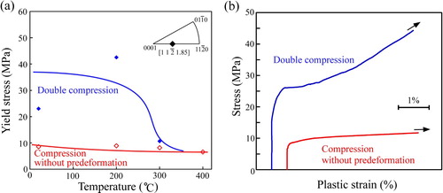
At 300°C, however, the yield stress suddenly decreased and was almost the same value as that of the specimen without predeformation. That is, kink-band strengthening loses its effect at 300°C. The deformation microstructure in Figure (e), in which the basal slip traces continue across the kink-band boundaries, supports this conclusion.
3.4. Origin of the anomalously strong kink-band strengthening
As described in Section 3.3, the yield stress at 45° orientation was largely increased by the double compression. As the reason for the increase in yield stress, three factors are considered; (1) strengthening by the introduced kink-band boundaries, (2) work-hardening by reaction with dislocations introduced during the first deformation, and (3) variation in crystal orientation (Schmid factor) by the kink-band formation. Regarding (2), the work-hardening rate in deformation at 45° orientation is inherently small as shown in Figure (b). In addition, since the deformation modes other than the kink-band formation are not predominately expected to be activated in the first deformation owing to the existence of LPSO nanoplates [Citation24], the influence of the work-hardening induced by introduced dislocations is supposed to be small. However, a precise evaluation on this must be conducted in the future study. Regarding (3), the crystal rotation angle at the kink-band boundary was roughly 15° in average. This crystal rotation reduces the Schmid factor for a basal slip from 0.50 to 0.43, inducing just the 1.2 times to increase in yield stress. This is much smaller than the 3–4 times increase measured in this study. In addition, the variation in crystal orientation cannot explain the origin of the increase in the work-hardening rate and the drastic drop of the yield stress at 300°C in the double compression test. Thus, the influence of (1); the strengthening by the introduced kink-band boundaries, is considered as the predominant strengthening mechanism in the double compression test.
To evaluate the strengthening effect by the kink-band boundaries quantitatively, a Hall–Petch-like analysis was conducted. The definition of the measurement method is schematically explained in Supplementary Fig. S2. On the observed (100) specimen surface shown in Figures and , the direction of the Burgers vector of operative [11
0] basal dislocation in the second compression test is ∼45° inclined with respect to the loading axis. Thus, if regarding the kink band boundary as the grain boundary, the distance between the kink-band boundary, l, directly corresponds to the mean free path of the operative [11
0] basal dislocation. Therefore, the distances between the kink-band boundary indicated by the arrows in Figure (a), across which crystal rotation of more than 3° occurred, were measured on the (1
00) specimen surface, and the Hall-Petch coefficient ky was evaluated. The average distance between the kink-band boundary was ∼244 μm and the standard deviation was ∼145 μm in specimen deformed at RT.
Figure 4. (a) Deformation traces introduced in the specimen by the double compression test at RT. (b) Higher-magnification image of the kink-band boundary. (c) Drastic decrease in the contrast of the basal slip traces beyond the accumulated kink-band boundaries, seen at the bottom right part in the image.
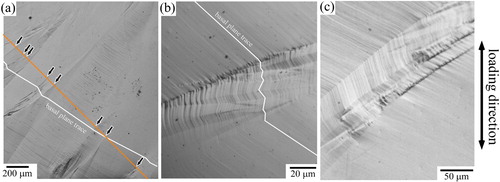
Table summarizes the obtained results and the values previously reported for other Mg alloys [Citation25–29]. The measured ky at RT was 226 MPa·μm1/2, which is comparable to those measured for polycrystalline Mg alloys. Although the yield stress at 200°C showed higher value than that at RT in the double compression test shown in Figure , the measured ky was slightly decreased to 178 MPa·μm1/2 at 200°C. This indicates that the scatter of the yield stress between RT and 200°C is derived from the variation in the number of the introduced kink band boundary during the first deformation.
Table 1. Values of ky from the Hall–Petch-like plot, estimated by regarding a kink-band boundary as a grain boundary in the double compression test. The values measured for polycrystalline Mg and Al alloys reported in [Citation25–31] are also listed for comparison. The values in parentheses indicate those evaluated from the higher-magnification image shown in Figure (b).
Note that ky for Mg alloys at RT is higher than those for face-centered cubic (fcc) Al alloys [Citation30,Citation31], because the number of operative slip systems is smaller in hexagonal close-packed (hcp) Mg alloys owing to the lower crystal symmetry. Thus, grain refining is a more important strengthening mechanism for Mg alloys. It is generally considered that the strengthening effect due to low-angle tilt boundaries is weak [Citation32]. A kink-band boundary has the same geometry as a tilt boundary in the simple dislocation alignment model proposed by Hess and Barret [Citation16], as shown in Supplementary Fig. S1; thus, its strengthening effect was assumed to be weak. However, the present results demonstrate that the ability of a kink-band boundary to act as an obstacle to dislocation motion is comparable to that for a general random grain boundary. One of the reasons for this is related to the difference in dislocation density at the boundary. Although a kink-band boundary might also be formed due to dislocation alignment, dislocation density at the kink-band boundary could be much higher than that of low-angle grain boundaries. Since the observed crystal rotation angle is frequently higher than 15°, as described later.
Another reason for this anomalously high ability of a kink-band boundary to act as a barrier is related to the accumulative formation behavior of a kink band in a localized region. Figure (b) shows a higher-magnification image of a kink-band boundary. Even the kink-band boundary observed as ‘single' boundary in the low-magnification images (Figures (a) and 4(a)), it is often confirmed to be constructed by the accumulation of multiple kink-band boundaries. The crystal rotation angle for the accumulated small kink bands is as large as ∼2°–60°, which is much larger than the crystal rotation angle in the matrix region of ∼2°–30°. The accumulation of kink-band boundaries with high crystal rotation angles should induce a strong barrier to dislocation motion. Indeed, the drastic decrease in the contrast of the basal slip traces was frequently observed beyond such the accumulated kink-band boundaries as shown in Figure (c).
Regarding the accumulated kink-band boundaries, if counting the number of boundaries in the high-magnification images shown in Figure (b), the value of ky is reduced from 226 to ∼100 MPa·μm1/2, as indicated in parentheses in Table , since the analyzed average distance between the kink-band boundary is reduced from ∼244 to ∼48 μm. It must be noted here that the observed boundaries will be further resolved in images obtained with transmission electron microscopy (TEM) at even higher magnification, as reported in [Citation19,Citation21,Citation33–35], and thus the distance is further reduced. Thus, the evaluation of ky is measured to be magnification-dependent. However, the ky-value measured in the high-magnification is the ‘apparent' value, and the value measured in the low-magnification observation must be important for controlling the strength of the alloy. This hierarchical structure of the kink-band boundary plays a significant role in inducing a strong barrier that hinders dislocation motion, which is comparable to that for a general random grain boundary.
4. Conclusion
It was clarified that a kink-band boundary has the ability to act as a barrier that hinders the motion of dislocations, which is comparable to general random grain boundaries. This is due to its peculiar hierarchical structure, in which many small kink bands with high crystal rotation angles accumulate in a localized region. The results demonstrate the importance of the control of the kink-band formation behavior for effectively inducing the ‘kink-band strengthening’.
Supplemental Material
Download PDF (481.2 KB)Disclosure statement
No potential conflict of interest was reported by the author(s).
Data availability
The raw/processed data required to reproduce these findings cannot be shared at this time as the data also forms part of an ongoing study.
Additional information
Funding
References
- Kawamura Y, Hayashi K, Inoue A, et al. Rapidly solidified powder metallurgy Mg97Zn1Y2 alloys with excellent tensile yield strength above 600 MPa. Mater Trans. 2001;42:1172–1176.
- Hagihara K, Kinoshita A, Sugino Y, et al. Effect of long-period stacking ordered phase on mechanical properties of Mg97Zn1Y2 extruded alloy. Acta Mater. 2010;58:6282–6293.
- Hagihara K, Kinoshita A, Sugino Y, et al. Plastic deformation behavior of Mg89Zn4Y7 extruded alloy composed of long-period stacking ordered phase. Intermetallics. 2010;18:1079–1085.
- Yamasaki M, Hashimoto K, Hagihara K, et al. Effect of multimodal microstructure evolution on mechanical properties of Mg–Zn–Y extruded alloy. Acta Mater. 2011;59:3646–3658.
- Oñorbe E, Garcés G, Pérez P, et al. Effect of the LPSO volume fraction on the microstructure and mechanical properties of Mg–Y2X–ZnX alloys. J Mater Sci. 2012;47:1085–1093.
- Wang J, Song P, Zhou X, et al. Influence of the morphology of long-period stacking ordered phase on the mechanical properties of as-extruded Mg–5Zn–5Y–0.6Zr magnesium alloy. Mater Sci Eng A. 2012;556:68–75.
- Hagihara K, Kinoshita A, Fukusumi Y, et al. High-temperature compressive deformation behavior of Mg97Zn1Y2 extruded alloy containing a long-period stacking ordered (LPSO) phase. Mater Sci Eng A. 2013;560:71–79.
- Oñorbe E, Garcés G, Dobes F, et al. High-temperature mechanical behavior of extruded Mg-Y-Zn alloy containing LPSO phases. Metall Mater Trans A. 2013;44:2869–2883.
- Tong LB, Li XH, Zhang HJ. Effect of long period stacking ordered phase on the microstructure, texture and mechanical properties of extruded Mg–Y–Zn alloy. Mater Sci Eng A. 2013;563:177–183.
- Garces G, Perez P, Cabeza S, et al. Reverse tension/compression asymmetry of a Mg-Y-Zn alloys containing LPSO phases. Mater Sci Eng A. 2015;647:287–293.
- Kim JK, Sandlöbes S, Raabe D. On the room temperature deformation mechanisms of a Mg-Y-Zn alloy with long-period-stacking-ordered structures. Acta Mater. 2015;82:414–423.
- Liu H, Bai J, Yan K, et al. Comparative studies on evolution behaviors of 14H LPSO precipitates in as-cast and as-extruded Mg-Y-Zn alloys during annealing at 773 K. Mater Design. 2016;93:9–18.
- Chen R, Sandlöbes S, Zeng X, et al. Room temperature deformation of LPSO structures by non-basal slip. Mater Sci Eng A. 2017;682:354–358.
- Garcés G, Máthis K, Medina J, et al. Combination of in-situ diffraction experiments and acoustic emission testing to understand the compression behavior of Mg-Y-Zn alloys containing LPSO phase under different loading conditions. Inter J Plast. 2018;106:107–128.
- Lyu J, Kim J, Liao H, et al. Effect of substitution of Zn with Ni on microstructure evolution and mechanical properties of LPSO dominant Mg–Y–Zn alloys. Mater Sci Eng A. 2020;773(138735).
- Hess JB, Barrett CS. Structure and nature of kink bands in zinc. Trans Am Inst Min Met Eng. 1949;185:599–606.
- Hagihara K, Yamasaki M, Honnami M, et al. Crystallographic nature of deformation bands shown in Zn and Mg-based long-period stacking ordered (LPSO) phase. Philo Mag. 2015;95:132–157.
- Egusa D, Abe E. The structure of long period stacking/order Mg–Zn–RE phases with extended non-stoichiometry ranges. Acta Mater. 2012;60:166–178.
- Hagihara K, Yokotani N, Umakoshi Y. Plastic deformation behavior of Mg12YZn with 18R long-period stacking ordered structure. Intermetallics. 2010;18:267–276.
- Hagihara K, Sugino Y, Fukusumi Y, et al. Plastic deformation behavior of Mg12ZnY LPSO-phase with 14H-typed structure. Mater Trans. 2011;52:1096–1103.
- Hagihara K, Okamoto T, Izuno H, et al. Plastic deformation behavior of 10H-type synchronized LPSO phase in a Mg-Zn-Y system. Acta Mater. 2016;109:90–102.
- Hagihara K, Li Z, Yamasaki M, et al. Strengthening mechanisms acting in extruded Mg-based long-period stacking ordered (LPSO)-phase alloys. Acta Mater. 2019;163:226–239.
- Hagihara K, Yamasaki M, Kawamura Y, et al. Strengthening of Mg-based long-period stacking ordered (LPSO) phase with deformation kink bands. Mater Sci Eng A. 2019;763:138163.
- Hagihara K, Ueyama R, Yamasaki M, et al. Surprising increase in yield stress of Mg single crystal using long-period stacking ordered nanoplates. Acta Mater. 2021;209:116797.
- Hauser FE, Landon PR, Dorn JE. Fracture of magnesium alloys at low temperature. Trans Metall Soc AIME. 1956;206:589–593.
- Ono N, Nowak R, Miura S. Effect of deformation temperature on Hall–Petch relationship registered for polycrystalline magnesium. Mater Lett. 2003;58:39–43.
- Barnett MR, Keshavarz Z, Beer AG, et al. Influence of grain size on the compressive deformation of wrought Mg–3Al–1Zn. Acta Mater. 2004;2:5093–5103.
- Nussbaum G, Sainfort P, Regazzoni G, et al. Strengthening mechanisms in the rapidly solidified AZ91 magnesium alloy. Scripta Metall. 1989;23:1079–1084.
- Mabuchi M, Chino Y, Iwasaki H, et al. The grain size and texture dependence of tensile properties in extruded Mg-9Al-1Zn. Mater Trans. 2001;42:1182–1189.
- Yu CY, Sun PL, Kao PW, et al. Mechanical properties of submicron-grained aluminum. Scripta Mater. 2005;52:359–363.
- Lianxi H, Yuping L, Erde W, et al. Ultrafine grained structure and mechanical properties of a LY12 Al alloy prepared by repetitive upsetting-extrusion. Mater Sci Eng A. 2006;422:327–332.
- Materials Science and Engineering an Introduction. 9th ed., Callister, WD Jr, editor. Wiley; 2014.
- Barsoum NW, Farber L, El-Raghy T. Dislocations, kink bands, and room-temperature plasticity of Ti3SiC2. Metall Mater Trans A. 1999;30:1727–1738.
- Egusa D, Yamasaki M, Kawamura Y, et al. Micro-kinking of the long-period stacking order (LPSO) phase in a hot-extruded Mg97Zn1Y2 alloy. Mater Trans. 2013;54:698–702.
- Matsumoto T, Yamasaki M, Hagihara K, et al. Configuration of dislocations in low-angle kink boundaries formed in a single crystalline long-period stacking ordered Mg-Zn-Y alloy. Acta Mater. 2018;151:112–124.