
 ?Mathematical formulae have been encoded as MathML and are displayed in this HTML version using MathJax in order to improve their display. Uncheck the box to turn MathJax off. This feature requires Javascript. Click on a formula to zoom.
Abstract
Topological phase inversion, in which γ'-precipitate becomes topological matrix phase, is a typical ‘detrimental’ microstructural degradation in Ni-based single-crystal superalloys. Here, a topologically inverse structure without service-induced damages is proposed. This structure exhibits excellent stress rupture properties at 1200°C and great microstructural stability, characterized by high, steady two-phase interface density. The relationship of the interface density to microscopic dislocation motion and macroscopic plastic deformation has been established, which reveals possible strengthening effect. These results will help understanding the benefit from this ‘degraded’ but quite stable microstructure and guide microstructure tuning against long-termed heat-resisted service.
GRAPHICAL ABSTRACT
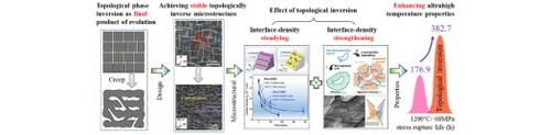
IMPACT STATEMENT
Topological phase inversion achieved after heat treatment exhibits great microstructural stability and enhanced 1200°C stress rupture properties of single-crystal superalloys. The mechanism behind this beneficial effect is uncovered.
1. Introduction
Ni-based single-crystal superalloys are key materials for hottest sections in aero-engines and gas turbines, and rendering them more resistant to elevating temperatures is extremely challenging [Citation1–4]. Their excellent performance relies on well-optimized matrix (γ phase) -precipitate (γ’ phase) microstructure [Citation5]. During high-temperature service, this microstructure inevitably degrades, as shown in Figure (a). During iso-thermal exposure as Figure (a)–(i), the γ'-precipitates continue to coarsen and interconnect via <001> directions. This is driven by the minimization of total free energy including chemical energy and elastic energy [Citation6–8]. During creep as Figure a-ii, both the elastic inhomogeneity and dislocation activity break the symmetry of energy distribution at γ/γ’ interfaces [Citation9–11], therefore causing beneficial directional rafting. This raft structure then has to collapse through forming γ'-junctions between rafts [Citation12]. Significantly, in both two final microstructures, the γ'-phase is no longer confined by the γ-matrix, and inversely, becomes the topological matrix phase [Citation13, Citation14]. This is called topological phase inversion. This inversion exhibits lower stress rupture strength [Citation15] and rapid creep rupture [Citation16, Citation17]. Recently, this structure is recognized as a critical symptom of service damage and failure [Citation18, Citation19] and actively researched by using advanced technological methods such as phase-field simulation [Citation20] and FIB reconstruction [Citation21, Citation22].
Which arouses our great curiosity is that the evolution or degradation of the inverse structure becomes significantly slower than the standard microstructure, due to the remarkable reduction in total free energy according to experimental [Citation15] and computational [Citation20] works. This microstructural stability should have potential beneficial effect. However, the aforementioned exposure- or creep-induced inversion usually accompanies with multi-scale structural damages [Citation18, Citation19, Citation23–28], such as alloying elements segregation, dislocation propagation, γ/γ’ interface distortion, deleterious phase precipitation and micro-voids growth, leading to poor mechanical properties. There is still a lack of research to distinguish the effect of topological inversion from the above harmful impacts.
Herein, we propose a topologically inverse structure with free of service-induced damages and give clear evidence of its mechanical properties and microstructural stability against ultrahigh temperature as 1200°C. The possible mechanism behind the beneficial effect of the inversion is revealed.
2. Materials and methods
A quinary single-crystal model superalloy is developed from our previous works [Citation29–31], where one 3 w.t.% Re-containing alloy exhibits 1200°C/ 80 MPa creep life longer than 110 h. This work chooses an alloy termed Alloy SMSC (Standard Microstructure Single Crystal), with the chemical composition (weight percent) of (7.5–7.9) Al- (9.3–9.9) Mo- (2.9–3.3) Ta- (1.2–1.5) Re- bal. Ni. According to Caron’s [Citation16] and Walston’s [Citation13] works where topological inversion could be facilitated by higher volume fraction of γ'-phase, at least higher than 50%, adding 0.5 w.t. % Al into Alloy SMSC generates an alloy termed Alloy TIMSC (Topologically Inverse Microstructure Single Crystal). For properties comparison, some alloys with Al or Ta content changed are also studied (see Part 1 of Supplementary Materials).
The single-crystal rods were achieved by high rate solidification (HRS) using screw selecting method and were chosen according to the orientations only within 8° deviating from the [001] orientation. The standard heat treatments were carried out as Supplementary Materials, where the 1200°C/1 h high-temperature aging is same at two alloys. The samples were submitted to 1200°C/100 h isothermal exposure and water quenched quickly. The 1200°C/60 MPa stress rupture tests were carried out according to the National Standard (GB/T 2039-2012). Each alloy was tested at least three times for averaging. The microstructure and dislocation configuration were observed using SEM and TEM. The interface density defined in this work is obtained as the interface line length per area in SEM images, by using ImageJ software. The filtered Fast Fourier transformation (fFFT) technology [Citation12] is applied for studying periodical γ–γ’ morphology. The fFFT transformation of γ–γ’ morphology image constructs a reciprocal space and generates a spectrum consisting of discrete points. The angular position of one discrete point represents the direction normal to the corresponding γ/γ’ interfaces, and the deviation of points from these principle orientations reflects interface distortion. (See Part 1 of Supplementary Materials.)
3. Results and discussion
Heat-treated microstructure. Figure b1 shows the heat-treated microstructure in Alloy SMSC, being representative of conventional two-phase microstructure [Citation12, Citation32]. The cubic γ'-precipitates embed in straight γ-channels. The fFFT points in Figure b2 are converged to [100] and [010] directions. It indicates that these γ/γ’ interfaces are of {100} crystallographic planes and keep straight.
In contrast, the heat-treated microstructure of Alloy TIMSC has the characteristic of topological inversion without service-induced damages. In Figure c1, the γ'-phase seems be the matrix, that is embedded by some skeleton-like γ-phases with numerous γ-terminations. The converging of fFFT points in Figure c2 is identical with Figure b2. This gives the evidence of almost straight interfaces. This straightness indicates that the microstructure is close to the state of standard heat treatment (see Part 2 of Supplementary Materials).
To quantitatively describe levels of topological inversion completion, a specific connectivity number of γ, denoted as , is introduced [Citation16].
is defined as the number of connected particles of γ phase per area unit, and it will change from negative to positive during topological inversing (see Part 3 of Supplementary Materials).
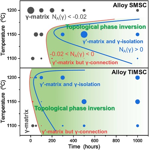
The time and temperature dependence of in Alloy SMSC and TIMSC are given in Figure . From Alloy SMSC, the temperature has a complex effect on the rate of topological inversion: the temperature increasing from 1100 to 1150°C enhances diffusion rate and inversion activity, while further increased temperature inhibits inversion. The latter is ascribed to γ'-dissolution. The volume fraction decreases to 48.4 ± 3.7% at 1200°C, which does not meet the 50%-fraction-to-inversion rule [Citation16]. Alloy TIMSC shows a significantly greater tendency to topological inversion at 1150–1200°C. Its remained γ'-phase at 1200°C is of 61.3 ± 4.3% volume fraction, still higher than 50%, which diminishes the impact of γ'-dissolution. This phenomenon can be explained by the greater thermal stability of γ'-phase in Alloy TIMSC, whose dissolution temperature is 1352°C, higher than Alloy SMSC (1323 °C).
Figure 1. Microstructural evolution at high temperature in conventional and topologically inverse single-crystal superalloys, the latter exhibiting much greater microstructural stability. (a) Schematic illustration for γ–γ’ microstructural evolution during high-temperature exposure or creep, where the grey shapes represent γ'-phases; (b1) conventional γ–γ’ morphology in Alloy SMSC after heat treatment, and (b2) its filtered Fast-Fourier-Transformation (fFFT) spectrum; (c1) inverse structure in Alloy TIMSC after heat treatment and (c2) its fFFT spectrum. Comparison of the microstructures after 1200°C/ 100 h exposed in (d) Alloy SMSC and (e) TIMSC and the microstructures ruptured at 1200°C/60 MPa in (f) Alloy SMSC and (g) TIMSC.
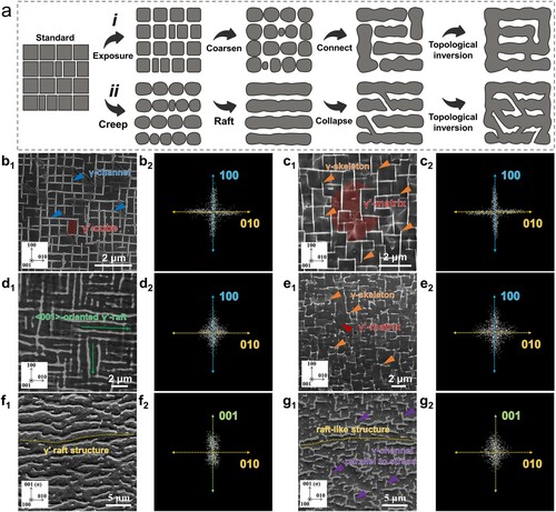
Figure 2. Temperature-time transformation diagram for Alloy SMSC and TIMSC showing a significantly greater tendency to topological inversion in the latter alloy. The radius of circles is proportional to the absolute value of specific connectivity number of γ . The red solid curve represents the time required at each temperature for initial inversion, featured by γ'-matrix with connected γ, and the blue one is for inversion completion.
It is also suggested that the treated microstructure will evolve rapidly to Figures b1 and c1 when submitted to 1200°C service. Our 1200°C/1 h high temperature aging can effectively reflect initial microstructure for ultrahigh-temperature testing. The inverse structure in Alloy TIMSC is not an ‘over-aging’ but a technologically standard structure for performance.
Ultrahigh temperature properties. The 1200°C/ 60 MPa stresses rupture lives of Alloy TIMSC and SMSC and other counterpart alloys are shown in Figure (a). Surprisingly, the life of Alloy TIMSC (382.7 ± 30.6 h) doubles that of Alloy SMSC (176.9 ± 24.8 h). It is found that these properties enhance with the increasing γ'-fractions at 1200°C, from approximately 40% to 60%. The gray range is the prediction based on the dependence on γ'-fraction, proposed by Takao Murakumo et al. [Citation33]. Our results are accordant with this prediction, which infers that γ'-fraction is the dominant factor for ultrahigh-temperature properties. More importantly, one can obtain that the inverse structure does not reduce properties, which in contrast to common wisdom.
Figure 3. Improved 1200°C/60 MPa stresses rupture properties in Alloy TIMSC. (a) Stresses rupture lives as a function of γ'-fraction at 1200°C; (b) comparison of stress rupture lives at 1200°C between our investigated alloys and conventional single-crystal superalloys [Citation34–37].
![Figure 3. Improved 1200°C/60 MPa stresses rupture properties in Alloy TIMSC. (a) Stresses rupture lives as a function of γ'-fraction at 1200°C; (b) comparison of stress rupture lives at 1200°C between our investigated alloys and conventional single-crystal superalloys [Citation34–37].](/cms/asset/d1e63ef5-10ce-4597-9464-c2c4e783187b/tmrl_a_1982785_f0003_oc.jpg)
Figure 4. Dislocation configuration after 1200°C/60 MPa stresses ruptured, showing strong dislocation-drag effect of interfaces. TEM images in ruptured Alloy SMSC or Alloy TIMSC along (a1 or b1) transverse and (a2 or b2) longitudinal directions; (c) typical dislocation configurations in a (001) interface; (d) this drag phenomenon exists in all interfaces, including (1) (001)-interface of Alloy SMSC and (2) (001)- and (3) (010)-interfaces of Alloy TIMSC; (e) observation of the dragged dislocations with lengths up to micrometers.
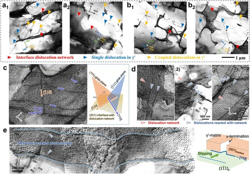
Figure 5. γ/γ’ interface density-steadying behaviour of the inverse structure and its dependence of properties. Comparison of interface morphology between (a) the γ'-raft; (b) inverse structure; (c) interface density as a function of testing time; (d) schematic diagram illustrating interface-strengthening mechanism taking into account the interface density; (e) relationship between
and the creep properties as the reciprocal of rupture life.
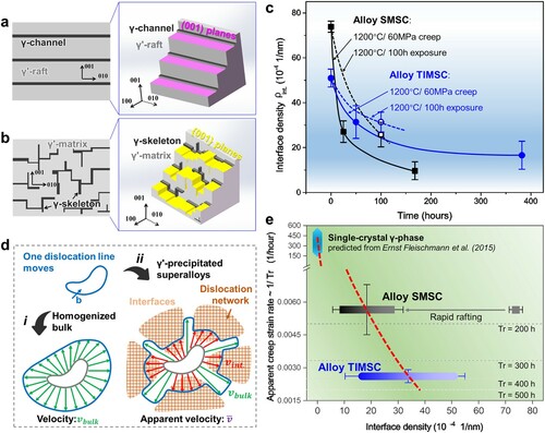
Figure (b) shows the stress rupture lives at 1200°C in our alloys and conventional single-crystal superalloys [Citation34–37]. The conventional design strategy has applied refractory elements such as Re and Ru to upgrade to next generation through doubling creep properties [Citation13, Citation38–40] (More supported data in Part 4 of Supplementary Materials). Alloy TIMSC has nearly doubled 1200°C/ 60 MPa stress rupture life than Alloy SMSC, just through adding proper Al content and tuning two-phase topological structure. Therefore, the topological inversion is a new promising way to upgrade superalloys.
Microstructural stability. The γ-γ’ morphology of two alloys after 1200°C/100 h exposed is shown in Figure (d and e), and the inverse structure exhibits a microstructure-stabilizing effect. The γ'-cubes interconnect along <100> directions and form <100>-orientated, short γ'-rafts in Alloy SMSC, while the structure in Alloy TIMSC remains quite similar to its heat-treated structure (Figure c1), still consisting of γ'-matrix and γ-skeletons. Their fFFT points (Figure d2-e2) both arrange along <100> directions with a remarkable dispersion. This indicates that the long-termed exposure distorts these interfaces.
The γ–γ’ morphology in two alloys ruptured at 1200°C/ 60 MPa is shown in Figure (f–g), indicating the inverse structure exhibits greater microstructural stability against applied stress. The γ'-precipitates in Alloy SMSC are first rafted perpendicular to applied stress and then becomes the topological matrix, as expected from common wisdom (Figure a-ii). The points distributed along [010] direction in Figure f2 diminish during this process. In contrast, the morphology of ruptured Alloy TIMSC in Figure g1 seems similar to that after heat treatment (Figure c1) and thermal exposure (Figure e1). The [010]-directed fFFT points still exist in Figure g2, which demonstrates the stability of [001]-orientated γ-skeletons.
The microstructural stability of our inverse structure is quite greater than conventional two-phase structure in Alloy SMSC and another inverse structure proposed by F. Vogel et al. [Citation41, Citation42], where γ-sphere precipitates from γ'-matrix and coarsens significantly during aging. Based on analysis of interface curvature in Figure 2S of Supplementary Materials, the main ripening phase is γ'-phase in Alloy SMSC as expected, while that in Alloy TIMSC is not simply either γ'-phase or γ-phase. This indicates that the mechanism of microstructural evolution in inverse structure maybe results from the interaction or competition between individual single-phase γ'- and γ-coarsening, which needs further research.
Besides, Topologically Close-Packed (TCP) phase precipitation is another key feature of microstructural stability. As shown in Figure , no TCP phase is presented after heat treatment, stress rupture test and thermal exposure at 1200°C. This thermal instability of TCP above 1150°C is also found in another Ni–Al–Mo series superalloy IC6 [Citation43] and other superalloys (see Part 5.2 of Supplementary Materials). Thus our investigated alloys have microstructural stability of no TCP precipitation, to eliminate the harmful effect of TCP.
Dislocation behavior. Figure (a and b) shows the dislocation configuration in two ruptured alloys. The contrast of γ-phases is remarkably black, which demonstrates complex dislocation motion confined in there during testing (see Part 6.1 of Supplementary Materials). The bright γ'-phases are just sheared by some dislocations in single or pair-coupled forms (see blue and yellow marks). These dislocations stopped on γ/γ’ interfaces weave into networks (see red marks in Figure a and b), to release lattice misfit stress and reduce interface energy [Citation40]. The Burgers vectors of these dislocations are defined as a/2<10>{111}, via two-beam diffraction contrast conditions tests. According to metallography, this kind of dislocations should form preferentially in disordered FCC structure of γ-phase. The pair-coupling of dislocations in γ'-phases indicates that the dislocations’ penetration into γ'-phases is inhibited mainly by antiphase boundary (APB) [Citation44] (see Part 6.2 of Supplementary Materials).
A typical dislocation network in a (001) interface is shown in Figure c, which consists of mutually vertical, periodically distributed dislocations. The dislocation-network interaction is investigated. Figure (c) also shows that some dislocations differing from networked dislocations locate in the interface, with line vectors of and
. These line vectors are the intersections between (111)- or (
)-glide planes and (001)-interface, as illustrated in Figure (c). One can infer that these subsequent dislocations, slipping via {111}-glide planes of γ-phase, have met the (001)-interface and, consequently, their line vectors change to the intersections of
. The subsequent dislocations are of low mobility, whose line vector remains along such intersection. This demonstrates the dislocation-drag effect, owing to some immobile dislocation segments produced by the reaction between subsequent dislocations and the network [Citation45, Citation46]. This drag process operates in not only the perpendicular-to-stress (001)-interfaces in both alloys (Figure d1 and 4d2) but also the parallel-to-stress (010)-interfaces in Alloy TIMSC (Figure d3). As shown in Figure (e), we have observed some 3–4-μm-long, dragged dislocations, with line vectors barely deviating from
. These results give the evidence of strong dislocation-drag effect of all interfaces in the investigated alloys.
The dislocation–microstructure interaction and the creep resistance mechanism are discussed. It is obvious that all the γ- and γ'-phases and their interfaces are sheared or interacted with dislocations. The dislocations motion causes plastic deformation [Citation47, Citation48], and hence, the resistance to plastic deformation originates mainly from the interaction between dislocations and two-phase structure. Four main strengthening mechanisms work, as shown below:
Solid solution strengthening: It slows dislocation motion in γ-phase.
Ordered structure strengthening: It inhibits dislocations’ penetration of γ'-phase by APB.
Precipitation strengthening: The γ'-raft structure (Figure f) and the raft-like γ'-matrix (Figure g) inhibit rapid dislocations’ cross-slip or slip-climb complex motion along the γ-channels parallel to applied stresses.
Interface strengthening: The dislocations confined in γ-phases have met the γ/γ’ interfaces and interact with interfacial dislocation networks [Citation40, Citation49]. This dislocation-drag process determines the climb of dislocations via the interfaces and their rate of escape from dragged configurations, being regraded the rate-controlling step of creep [Citation47, Citation48].
The last seems quite different in two alloys with varied topological phase structures, which is further researched in this work.
Interface quantity analysis. Figure (a and b) illustrates typical interface morphology in the γ'-rafted or inverse structure. These interfaces in the γ'-rafted structure are plane-typed (as pink planes), while those in the inverse structure are of continuous multi-planes type (as yellow planes). The inverse structure seems to have quite higher interface quantity than the rafted one. For the quantitative study, an interface density () is defined as the interface area per volume in three-dimensional scale.
Figure (c) shows the variation of interface density during creep. For Alloy SMSC, the interface density sharply drops to the one-third of heat-treated one due to the rafting process and reduces further with structure inversed. In contrast, the interface density of Alloy TIMSC keeps relatively steadier and quite higher than the rafted Alloy SMSC. After long-termed exposure, the interface of Alloy TIMSC is also denser than Alloy SMSC. Therefore, the inverse structure has higher and steadier interface density against service, being an important characteristic of its good microstructural stability.
Strengthening mechanism. Although the inverse structure in our work achieves the optimum γ'-fraction as approximately 60% [Citation33-35], its precipitate morphology fails to meet the well-accepted optimal shape (aligned cuboidal particle) and size (<0.5 μm with more negative misfit) for elevated temperature creep properties [Citation50]. There must be a possible strengthening effect to overcome such failure. However, the current interface-strengthening mechanism [Citation40, Citation49] could not explain our results, since (i) the misfit as a dominated factor is slightly different (between −6.07% and −5.61% in two alloys, see Part 7 of Supplementary Materials), and (ii) it gives less consideration of the significant difference of microstructural evolution, i.e. microstructural stability. Therefore, we have developed interface-strengthening mechanism taking the interface density into account, and uncovers the mechanism behind the beneficial effect of topological inversion.
Figure (d) illustrates the motion process of one mobile dislocation line. If there is homogenized Ni solid solution (Figure d-i), the motion velocity of dislocation keeps constant as . When precipitates are presented (Figure d-ii), the dislocation segments meeting precipitates will be dragged by the interfacial dislocation networks, and the velocity correspondingly reduces to
. For simplicity, the apparent velocity
is assumed as a velocity average weighted with passed areas (
,
and
for bulk, interfacial and all parts, respectively), that is,
(1)
(1)
The ratio of
to
can describe the probability with which the dislocation meets the interfaces. A term
is introduced, where
is defined as the possible area of dislocation movement per volume, which represents dislocation mobility. The term
can also describe the meeting probability of dislocations and interfaces, which can substitute the ratio of
to
. There then is
(2)
(2)
According to Orowan’s equation, the macroscopic creep strain rate
can be described as
(3)
(3)
where
represents the density of mobile dislocation, and b is the modulus of Burgers vector of these dislocations. Combining the Equations (2) and (3), there is
(4)
(4)
This equation has modified the strengthening mechanism taking into account the solid solution, the interfacial lattice misfit and the interface density. The first item (
) represents the creep strain rate of γ-solid solution, controlled by solid solution degrees [Citation51]. Adding γ-partitioning elements, such as W, Mo, Re and Ru, will reduce
and hence decrease
. The second item (
) reflects the interface-strengthening effect. (i) There is
, due to not only the dragging effect of dislocation network [Citation40, Citation49], but also the antiphase boundary energy which prevents dislocations’ penetration of γ'-phase [Citation44]. Adding Mo, Ru and Re elements will make the misfit more negative, leading to lower
and correspondingly lower
. (ii) More importantly, the proportional factor of
and
is determined to be negative, owing to the negativity of the term
. One can obtain that the greater the interface density during service is, the more resistance to plastic deformation the alloy exhibits.
Equation (4) has been supported by our results. Monkman–Grant relationship shows , where
is the time to rupture under creep or stress rupture test. Figure (e) shows the plots of
against
, where the
ranges are used due to microstructure being evolving during test. When interface density comes to 0, the second item of Equation (4) diminishes and the creep rate is the plastic deformation behavior of single-phase single-crystal γ-solid solution, predicted by Ref. [Citation52] (see Part 8 of Supplementary Materials). It is confirmed that the interface density significantly reduces the creep strain rate. Thus the potential strengthening effect of the inverse structure can be reasonably attributed to its higher and steadier interface density, i.e. greater microstructural stability.
4. Conclusion
The topologically inverse structure is determined to have greater ultrahigh temperature properties. This improvement is related to not only the optimum γ'-fraction but also the excellent microstructural stability, with an important characteristic of higher and steadier interface density. Our work has uncovered the possible mechanism behind the beneficial effect of this inversion. This overturns the ‘failure-symptom’ stereotype of the inversion and opens up new possibilities to further breakthrough servicing temperature limit of superalloys and other heat-resisted materials.
Supplemental Material
Download PDF (554.9 KB)Acknowledgements
This research is sponsored by the National Natural Science Foundations of China (Nos. 51971010 and 92060301), the National Key Research and Development Program of China (No. 2017YFA0700700), and the National Science and Technology Major Project (Nos. 2019-VI-0016-0131, 2017-VI-0012-0084 and 2017-VI-0011-0083).
Disclosure statement
No potential conflict of interest was reported by the author(s).
References
- Perepezko JH. The hotter the engine, the better. Science. 2009;326:1068–1069.
- Pollock TM. Alloy design for aircraft engines. Nat Mater. 2016;15:809–815.
- Reed RC. The superalloys. New York: Cambridge University Press; 2006.
- Ghiaasiaan R, Muhammad M, Gradl PR, et al. Superior tensile properties of hastelloy X enabled by additive manufacturing. Mater Res Lett. 2021;9:308–314.
- Yuan SY, Jiang ZH, Liu JZ, et al. Nano-twinning in a γ′ precipitate strengthened Ni-based superalloy. Mater Res Lett. 2018;6:683–688.
- Wu R, Yue Z, Wang M. Effect of microstructure on creep of single crystal nickel-based superalloys: A phase-field simulation incorporating dislocation dynamics. J Alloys Compd. 2019;779:326–334.
- Wu R, Zaiser M. Cyclic-loading microstructure-property relations from a mesoscale perspective: An example of single crystal nickel-based superalloys. J Alloys Compd. 2019;770:964–971.
- MacKay RA, Nathal MV. Γ′ coarsening in high volume fraction nickel-base alloys. Acta Metall Mater. 1990;38:993–1005.
- Wu R, Sandfeld S. A dislocation dynamics-assisted phase field model for nickel-based superalloys: The role of initial dislocation density and external stress during creep. J Alloys Compd. 2017;703:389–395.
- Wu R, Sandfeld S. Insights from a minimal model of dislocation-assisted rafting in single crystal nickel-based superalloys. Scr Mater. 2016;123:42–45.
- Wu R, Zhao Y, Liu Y, et al. High temperature creep mechanisms of a single crystal superalloy: A phase-field simulation and microstructure characterization. Progr Natural Sci Mater Int. 2020;30:366–370.
- Epishin A, Link T, Portella PD, et al. Evolution of the γ/γ′ microstructure during high-temperature creep of a nickel-base superalloy. Acta Mater. 2000;48:4169–4177.
- Walston W, hara K, Ross E, et al. Superalloys. 1996;1996:27–34.
- Epishin A, Link T, Brückner U, et al. Kinetics of the topological inversion of the γ/γ′-microstructure during creep of a nickel-based superalloy. Acta Mater. 2001;49:4017–4023.
- Acharya MV, Fuchs GE. The effect of long-term thermal exposures on the microstructure and properties of CMSX-10 single crystal Ni-base superalloys. Mater Sci Eng A. 2004;381:143–153.
- Caron P, Ramusat C, Diologent F. Superalloys. 2008;2008:159–167.
- Huang YS, Wang XG, Cui CY, et al. The effect of coarsening of γ′ precipitate on creep properties of Ni-based single crystal superalloys during long-term aging. Mater Sci Eng A. 2020;773:138886.
- Li Y, Wang L, Zhang G, et al. Mater Sci Eng A. 2021;809.
- Xu K, Wang G, Liu J, et al. Mater Sci Eng A. 2020;786.
- Goerler JV, Lopez-Galilea I, Mujica Roncery L, et al. Topological phase inversion after long-term thermal exposure of nickel-base superalloys: experiment and phase-field simulation. Acta Mater. 2017;124:151–158.
- Antonov S, Zheng Y, Sosa JM, et al. Plasticity assisted redistribution of solutes leading to topological inversion during creep of superalloys. Scr Mater. 2020;186:287–292.
- Ziętara M, Kruk A, Gruszczyński A, et al. FIB–SEM tomography of 4th generation PWA 1497 superalloy. Mater Charact. 2014;87:143–148.
- Wu X, Makineni SK, Liebscher CH, et al. Unveiling the Re effect in Ni-based single crystal superalloys. Nat Commun. 2020;11:389.
- Oruganti R. A new approach to dislocation creep. Acta Mater. 2012;60:1695–1702.
- Reed RC, Cox DC, Rae CMF. Damage accumulation during creep deformation of a single crystal superalloy at 1150°C. Mater Sci Eng A. 2007;448:88–96.
- le Graverend J-B, Adrien J, Cormier J. Ex-situ X-ray tomography characterization of porosity during high-temperature creep in a Ni-based single-crystal superalloy: toward understanding what is damage. Mater Sci Eng A. 2017;695:367–378.
- Zhou G, Pantleon W, Xu R, et al. Quantification of local dislocation density using 3D synchrotron monochromatic X-ray microdiffraction. Mater Res Lett. 2021;9:182–188.
- Qin Z, Wang Z, Wang Y, et al. Phase prediction of Ni-base superalloys via high-throughput experiments and machine learning. Mater Res Lett. 2020;9:32–40.
- Ru Y, Zhang H, Pei Y, et al. Improved 1200 °C stress rupture property of single crystal superalloys by γ′-forming elements addition. Scr Mater. 2018;147:21–26.
- Ru Y, Zhang H, Pei Y, et al. Substituting Mo for Re in equal weight for Ni based single crystal superalloy. Materialia. 2019;6:100278.
- Ru Y, Zhao H, Zhang H, et al. Design for anomalous yield in γ′-strengthening superalloys. Mater Des. 2019;183:108082.
- Xia W, Zhao X, Yue L, et al. Microstructural evolution and creep mechanisms in Ni-based single crystal superalloys: A review. J Alloys Compd. 2020;819:152954.
- Murakumo T, Kobayashi T, Koizumi Y, et al. Creep behaviour of Ni-base single-crystal superalloys with various γ′ volume fraction. Acta Mater. 2004;52:3737–3744.
- D. Argence, C. Vemault, Y. Desvallces, D. Foumier, Superalloys, 2000 (2000) 829-837.
- P. Caron. Superalloys. 2000;2000:737–746.
- Reed RC, Matan N, Cox DC, et al. Creep of CMSX-4 superalloy single crystals: effects of rafting at high temperature. Acta Mater. 1999;47:3367–3381.
- Wahl J, Harris K. In: proceedings of ASME Turbo expo 2020. Turbomachinery technical conference and exposition, virtual, 2020, pp. V008T018A013.
- Sato A, Harada H, Yeh A-C, et al. Superalloys. 2008;2008:131–138.
- Erickson GL. Superalloys. 1996;1996:35–44.
- Zhang JX, Murakumo T, Harada H, et al. Dependence of creep strength on the interfacial dislocations in a fourth generation SC superalloy TMS-138. Scr Mater. 2003;48:287–293.
- Vogel F, Wanderka N, Balogh Z, et al. Mapping the evolution of hierarchical microstructures in a Ni-based superalloy. Nat Commun. 2013;4:2955.
- Vogel F, Ngai S, Fricke K, et al. Tracing the three-dimensional nanochemistry of phase separation in an inverse Ni-based superalloy. Acta Mater. 2018;157:326–338.
- Han YF, Li SH, Jin Y, et al. Effect of 900–1150 °C aging on the microstructure and mechanical properties of a DS casting Ni3Al-base alloy IC6. Mater Sci Eng A. 1995;192-193:899–907.
- Reppich B, Schepp P, Wehner G. Some new aspects concerning particle hardening mechanisms in γ' precipitating nickel-base alloys—II. experiments. Acta Metall. 1982;30:95–104.
- Agudo Jácome L, Nörtershäuser P, Somsen C, et al. On the nature of γ′ phase cutting and its effect on high temperature and low stress creep anisotropy of Ni-base single crystal superalloys. Acta Mater. 2014;69:246–264.
- Hantcherli M, Pettinari-Sturmel F, Viguier B, et al. Evolution of interfacial dislocation network during anisothermal high-temperature creep of a nickel-based superalloy. Scr Mater. 2012;66:143–146.
- Zhu Z, Basoalto H, Warnken N, et al. A model for the creep deformation behaviour of nickel-based single crystal superalloys. Acta Mater. 2012;60:4888–4900.
- Ma A, Dye D, Reed RC. A model for the creep deformation behaviour of single-crystal superalloy CMSX-4. Acta Mater. 2008;56:1657–1670.
- Carroll LJ, Feng Q, Pollock TM. Interfacial dislocation networks and creep in directional coarsened Ru-containing nickel-base single-crystal superalloys. Metallurgical and Materials Transactions A. 2008;39:1290–1307.
- Nathal MV. Effect of initial gamma prime size on the elevated temperature creep properties of single crystal nickel base superalloys. Metall Trans A. 1987;18:1961–1970.
- Aifantis EC. On the problem of diffusion in solids. Acta Mech. 1980;37:265–296.
- Fleischmann E, Miller MK, Affeldt E, et al. Quantitative experimental determination of the solid solution hardening potential of rhenium, tungsten and molybdenum in single-crystal nickel-based superalloys. Acta Mater. 2015;87:350–356.