
 ?Mathematical formulae have been encoded as MathML and are displayed in this HTML version using MathJax in order to improve their display. Uncheck the box to turn MathJax off. This feature requires Javascript. Click on a formula to zoom.
Abstract
Phase transformation is rare in pure body-centered cubic (BCC) metals due to the associated high energy barrier. Here, omega (ω) phase transformation in single-crystal niobium (Nb) under compression at 77 K was studied by atomistic characterization and density functional theory (DFT) calculation. The ω phases were found to nucleate preferentially at the boundaries of 112 shear bands, via a sequence of BCC-to-ω structural transformation induced by shear stress. Theoretically, calculations reveal that the formation of a shear transition region can reduce the energy barrier of BCC-to-ω phase transformation. These findings provide insights into the phase transformation involved in the cryogenic deformation of bulk BCC metals.
IMPACT STATEMENT
Atomistic characterization reveals the structural evolution of shear band mediated ω phase transformation in single-crystal Nb at the atomic scale, where a finite shear distortion of the lattice can greatly reduce the associated transformation barrier.
1. Introduction
Omega (ω) phase is a metastable hexagonal structure in numerous group IV and V transition metals, such as β-Ti, Hf, Ta and their alloys. It has attracted great attention for decades due to its marked effects on the mechanical and superconducting properties of metals [Citation1–3]. Based on the formation mechanisms, the ω phases can be classified into two types: the isothermal ω [Citation4] or adiabatic ω phases [Citation5] formed during the heat treatment, and the ω phases produced by plastic deformation (i.e. the so-called stress-induced ω phases) [Citation2,Citation6]. Currently, most studies of stress-induced ω phase are limited to alloys, where the addition of alloying elements can greatly reduce the potential energy barrier of ω phase transformation. Besides, most of the stress-induced ω phases were observed at or above room temperature, since the ω phase becomes more stable with the increase of pressure and temperature [Citation7]. In pure body-centered cubic (BCC) metals, some researches also reported the stress-induced ω phase but mainly under extreme conditions, such as high-speed shock [Citation8], laser compression [Citation9,Citation10] and severe plastic deformation [Citation11]. Under the deformation condition of low temperature, the flow stress in materials increases significantly, which may stimulate some unexpected deformation mechanisms. A recent study of BCC high entropy alloy HfNbTaTiZr reported that ω phase transformation can occur at 77 K and contribute to enhanced mechanical properties with negligible loss of elongation [Citation12]. Theoretically, the ω phase can be formed individually by the mechanism of lattice shear with the 1/12<11>, 1/3<11
> and 1/12<11
> inhomogeneous sliding on consecutive 112 planes [Citation8,Citation13]. Some studies on pure BCC metals also showed that the ω phase can be coupled with interfacial defects such as grain boundaries [Citation11] and twin boundaries [Citation14]. In these deformation processes, the lattice at the interfaces should be subjected to a localized high shear distortion [Citation15–18], which may facilitate the formation of ω phase. However, the associated coupling behavior remains largely unclear due to the lack of direct atomistic evidence.
In this study, we investigate the formation mechanism of ω phase in single-crystal Nb deformed at 77 K using aberration-corrected transmission electron microscopy. Atomistic observations show that the ω phases nucleate preferentially at the boundary of 112 shear band. Quantitative characterizations exhibit a sequence of BCC-to-ω structural transformation at the shear band interface. Density functional theory (DFT) calculations confirm that the energy barrier of the BCC-to-ω phase transformation can be reduced by the local shear of BCC phase. These findings uncover a low-energy pathway for phase transformation in pure metals.
2. Materials and methods
High-purity (99.9 wt.%) single-crystal Nb samples with the orientations of [100], [110], [111] were cut into dimensions of 1.1 mm × 1.1 mm × 1.1 mm and compressed at 77 K with strain rate (∼10−3 s−1). The samples were compressed with different strains to study the deformation structures (see Figure captions for details). After deformation, microstructures of deformed Nb were examined using an FEI Titan G2 60–300 aberration-corrected electron microscope at 300 kV. The TEM samples were electro-polished at −50 °C with a chemical solution of 558 ml CH3OH, 30 ml H2SO4, and 12 ml HF. DFT calculations were employed to study the stability of BCC and ω phases under finite shear strains. The calculations were performed using Vienna ab initio Simulation Package (VASP) with generalized gradient approximation (GGA) exchange–correlation density functional and ultrasoft pseudopotential [Citation19]. A plane-wave basis set with a 450 eV cutoff energy was adopted. A Γ-centered Monkhorst–Pack [Citation20] scheme with a 12 × 12 × 1 grid mesh was used for the 14-layer supercell model. The minimization convergence criterion was set to be 1.0 × 10⁻⁵ eV and 1 meV/Å for the energy and the force, respectively.
3. Results
Figure shows the deformation-induced shear band in Nb samples under [100], [110] and [111] compression. At a low compressive strain of 5%, dislocation activities dominate the plastic deformation of samples with different orientations (Figure S1). With the increasing strain, shear bands are extensively observed, as shown in Figure . In all cases, the shear band interfaces are largely located on the 112 plane, which are therefore denoted as 112 shear bands. Interestingly, the metastable ω phase was extensively observed at the boundaries of these shear bands. Figure (a) presents a bright-field TEM image of 112 shear band in Nb sample under [100 compression as observed in 110 zone axis. According to the previous reports [Citation2,Citation21], ω phase can be identified from the superlattice diffraction spots excited at various 1/3<112>BCC and 2/3<112>BCC positions on the ([13]BCC//[
23]ω) or ([011]BCC//[
20]ω) zone axis patterns. In the inset of Figure (a), the corresponding selected area electron diffraction pattern indicates the co-existence of BCC matrix and ω phase in the deformed Nb, with the orientation relationships between BCC matrix and ω phase of [
13]BCC//[
23]ω and [011]BCC//[
20]ω. By selecting the red-circled diffraction spot in Figure (a), the dark-field TEM image clearly shows the existence of ω phase, with a length of ∼400 nm along the 112 shear band boundary (Figure (b)). Similarly, the deformation structures of [110]- and [111]-compressed Nb single crystals also confirm the co-existence of 112 shear band and ω phase, with the ω phases mainly locating at the shear band interfaces (Figure (c–f)). A zoomed-in image shows a small ω phase embryo on the 112 shear band boundary (indicated by the red lines in Figure (d)), with 3 nm in width and 22 nm in length (confirmed by the FFT pattern in the inset of Figure (c)). These characterizations indicate that the formation of 112 shear band and ω phase could be a coupled process in Nb single crystals. Theoretically, the formation of ω phase can be induced by the inhomogeneous shear/shuffle in consecutive 112 planes [Citation8,Citation13]. Here the Schmid factor for dislocation slip on 112 plane is always larger than that of 110 plane under 100- 110- and 111]-compression of Nb single crystals (see Table ), which, in conjunction with the higher elastic energy in the severe deformed region, favors the formation of ω phase at low temperature [Citation22]. In this process, few ω phases independent of shear bands may occur occasionally, which should be induced by the dense dislocation activities in regions lack of 112 shear band, as demonstrated by the example in [111]-compressed sample (Figure S2). Hence, our observations have shown the general phenomenon of 112 shear band mediated ω phase transformation in Nb single crystals at low temperature.
Figure 1. Shear band mediated ω phase transformation in Nb under (a,b) [100]-, (c,d) [110]- and (e,f) [111]-compression, respectively. The compression strains for [100], [110], and [111]-samples are 20%, 20%, and 15%, respectively. The viewing direction of (a,b,e,f) are along the [011]BCC//[]ω and (c,d) are along the [
13]BCC//[
23]ω.
![Figure 1. Shear band mediated ω phase transformation in Nb under (a,b) [100]-, (c,d) [110]- and (e,f) [111]-compression, respectively. The compression strains for [100], [110], and [111]-samples are 20%, 20%, and 15%, respectively. The viewing direction of (a,b,e,f) are along the [011]BCC//[1¯1¯20]ω and (c,d) are along the [1¯13]BCC//[1¯1¯23]ω.](/cms/asset/539802ac-e19f-406e-8109-6b452b326136/tmrl_a_1992523_f0001_oc.jpg)
Table 1. Largest Schmid factors on the 110<11> and 112<11
> dislocation slip systems for three loading orientations tested in Nb.
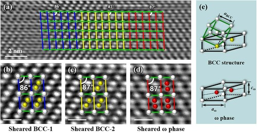
To reveal the atomistic BCC-to-ω transformation mechanism, Figure (a) (zoomed-in image of Figure (e)) shows a series of structural evolution of ω phase transformation at the boundary of 112 shear band. Along the 112 shear band boundary, the characteristic unit cells exhibit a severely distorted structure, with a gradual shear transition from BCC matrix to ω phase, as indicated by the change of the angles between [100]BCC and [110]BCC planes from the ideal 90° to 86° or 87°. This structure transition is subjected to the high shear strain without any dislocation observed in the nearby regions, consistent with the previous study on the shear band dynamics in W, where a local ‘shear region’ with high elastic strain concentration can be formed during the thickening process of a shear band [Citation23]. Figure (b–d) exhibits the enlarged HRTEM images of the sheared BCC and ω phases at the transition region. The distinct atom arrangements in the unit cell are important markers to distinguish the BCC and ω phases, as marked by the yellow and red dots in Figure (c,d). Clearly, the characteristic ideal BCC lattice gradually transits to the sheared BCC structure (including BCC-1 and BCC-2), sheared ω phase and then ω phase at the boundary of 112 shear band in sequence. The BCC-1 phase has a characteristic angle of 86°, corresponding to a shear strain of 7% with respect to the BCC lattice. The lattice distortion in BCC-2 is slightly smaller than that of BCC-1, which may be caused by stress relaxation after ω phase transformation [Citation22]. Figure (e) further presents a schematic illustration of the crystallographic relationship between the ideal BCC lattice and hexagonal ω lattice. The primitive unit cell of ω structure is specified by two lattice constants aω and cω, which theoretically are aω= = 0.472 nm and cω=
/2 = 0.289 nm (c/a=0.613) for Nb. Previous studies on the formation mechanism of stress-induced ω phase were all based on ideal crystallographic relationships between BCC and ω lattice but ignored the effect of external loading on the entire lattice [Citation1,Citation7,Citation24]. In this regard, our HRTEM observations indicate that the ω phase transformation mediated by shear band needs a distortion of the entire lattice.
Figure 2. Structural evolution of sheared ω phase transformation at a 112 shear band boundary. (a) A series of structures featuring the shear-induced ω phase transformation. (b,c) show a change in the BCC structure, and (c,d) shows the ω phase transformation. Scale bar, 0.5 nm. (e) Ideal atomic model of BCC structure and ω phase.
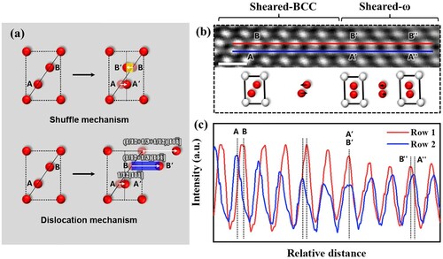
Theoretically, ω phase transformation can be induced by either shuffle mechanism or dislocation mechanism. In the former, ω phase is obtained by the motion of atoms on two adjacent (11) planes with a shuffle of 1/12[
1] and 1/12[11
], while leaving the third (11
) plane fixed [Citation1]; in the latter, such transition is realized by the sequential glide of partial dislocations of 1/12[
1], 1/3[
1] and 1/12[
1] on 2
1 planes [Citation8]. These differences are schematically shown by the relative motion behaviors of specific atoms (e.g. A and B) in a unit cell of BCC lattice in Figure (a), based on which we can distinguish the shuffle and dislocation mechanisms during the transformation. Following these differences, Figure (b,c) presents two adjacent rows of atoms (A and B) and their corresponding intensity profiles for analyzing the relative displacements between neighboring atom columns. As shown in Figure (b,c), the neighboring atom columns A and B in the BCC unit cell show a continuous change of the relative displacement between them, forming a sheared-BCC region. With the reduction of displacement between columns A and B, a unit cell of ω phase forms at the position where columns A and B are aligned to the same vertical direction (A′ and B′). Once a region of ω phase nucleates, it would further shuffle/distort the lattice slightly by forming a sheared-ω phase, as demonstrated by the relative displacement of the atom columns A″ and B″ (Figure (c)). Therefore, these observations suggest that the ω phase transformation should proceed in a manner of shuffle mechanism, involving the relative displacements of atoms on two adjacent (11
) planes of BCC lattice. Although our atomic observations confirm the shuffle mechanism during ω phase transformation, the dislocation mechanism cannot be fully excluded given dense dislocations in our samples.
Figure 3. Atomic shuffle of ω phase transformation. (a) Differences between the shuffle/dislocation mechanisms. (b) HRTEM image and (c) comparison of intensity profiles for atom columns along red and blue lines. Scale bar, 0.5 nm.
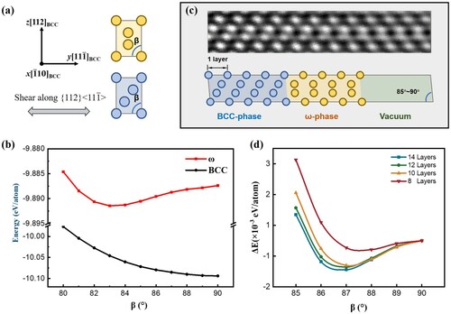
DFT calculations are further employed to evaluate the energy variations during the ω phase transformation under 112<11> shear strain on the interface of 112 shear band. Firstly, the stability of the BCC and ω phase under 112<11
> shear strain are compared. Shear strain is applied to deform the lattice angle β (Figure (a)) from 90° to 80°, and then the shape of the cell is fixed to calculate its energy. As shown in Figure (b), the energy of BCC phase increases gradually with the shear strain. In stark contrast, the energy of ω phase decreases with the shear strain and reaches an energy minimum at ∼83°, suggesting that a finite lattice shear can stabilize the ω phase. Moreover, the shear strain corresponding to β = 83° is γ = tan (−7°) = −12.3%, far beyond the elastic strain limit that a crystal lattice can bear [Citation25], which would evolve to another metastable state. Therefore, though the energy value of ω phase is still higher than that of BCC phase within the range of angle β allowed, the ultrahigh lattice distortion is likely to destabilize the BCC unit cell, facilitating the ω transformation as the lattice shear increases. This process can be confirmed by the co-existence of ω phase and BCC-1/BCC-2 phases with much lower lattice shear (less than 7%) at the shear band interface. To further simulate the energy change of two phases under the same shear strain, we build supercell models including a BCC-ω interface similar to the experimental observations (Figure (c)). To avoid the possible interactions of interface atoms owing to the periodic boundary condition [Citation26], a space with a thickness of 14 Å was set as vacuum in the supercell models. Then, the shear strain is introduced by changing the lattice angle β from 85° to 90°. The energy difference of the models containing different numbers of layers is obtained to avoid the influence of model size on the results. As the energy difference converges with the increasing model size, the BCC-ω-coupled structure reaches its minimum energy at β = 87°, in accordance with our experimental observations (Figure (d)). This result indicates that the formation of BCC-ω-coupled structures at the 112 shear band boundary represents the lowest energy state with the application of a local shear distortion.
Figure 4. DFT calculations of BCC and ω phase under 112<11> shear strain. (a) The supercell model of BCC and ω phase under the same shear strain. (b) Effect of shear strain on the energy of BCC and ω phase. (c) The BCC-ω supercell models identical to the experimental observation. (d) Effect of the shear strain on the energy of BCC-ω supercell model.
In the deformation of BCC metals, both 110 and 112 shear band can occur, depending on the temperature and loading geometry of the single crystal [Citation27,Citation28]. In our experiments, ω phase transformations mainly occur at the interface of 112 shear bands in Nb samples with three different orientations, while no 110 shear band is observed. To further explore the possibility of ω phase transformation at 110 shear band, the energy variations of BCC and ω phase under 110<11> shear (corresponding to the 110 shear band) are evaluated by DFT calculations. As shown in Figure S3, 110<1
1> shear fails to reduce the energy difference between BCC and ω phase, which, instead, even hinders the BCC-to-ω phase transformation, in contrast to the 112<11
> shear (Figure (b)). Therefore, whether the shear band can benefit the ω phase transformation is influenced by the specific type of the shear band.
4. Discussion
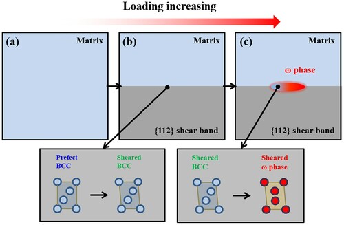
It is well-known that the plastic deformation of pure BCC metals is mainly dominated by dislocation slip [Citation27–30] and deformation twinning [Citation29,Citation31–34]. Addition of alloying elements can improve the stability of the metastable ω phase, favoring the ω phase transformation in BCC alloys [Citation1,Citation35]. However, the ω phase in pure metals is extremely hard to occur due to its high transformation barrier, except under severe deformation conditions. Moreover, ω phase transformation in BCC metals and alloys usually occurs at room temperature or above, where a higher temperature should be more favorable for such transition [Citation1]. Previous studies reported that the ω phase can be activated in pure Ta at an extremely high shocking pressure of ∼45 GPa [Citation8], or in pure Mo under the high-pressure torsion of 4 GPa [Citation11]. In these two processes, deformation-induced temperature rise is unavoidable, which may facilitate the ω phase. In our experiments, however, the ω phase transformation in pure Nb took place at 77 K with relatively low applied stresses, which, based on the engineering stress–strain curves, were estimated to be ∼1.1 GPa and ∼0.6 GPa for [100]- and [111]-compression, respectively. On one hand, the reduction of deformation temperature increases the lattice resistance for dislocation motion markedly. This would enhance the accumulation of internal stress/strain during deformation, especially at the shear band boundary, facilitating the ω phase transformation in BCC lattice. On the other hand, the compression-induced 112 shear band can further favor the formation of ω phase, given that both shear band and ω phase transformation in BCC metals involve 112 lattice shear [Citation8,Citation11,Citation36]. The low 112<111> shear modulus of Nb (23 GPa based on our DFT calculations) may also favor the shear transformation of lattice under applied loading; while, the formation of 112 shear band and resultant strain accumulation at its boundary can help to overcome the critical shear stress/strain required for the ω phase transformation (although the global stress applied on the sample could be relatively lower than that under severe plastic deformation, the local stress/strain accumulation at the shear band boundary can be sufficiently high), resulting in the ω phase in our Nb samples deformed at 77 K. In this process, the 112 shear band is activated by the massive dislocation activities under the compressive loading (Figure (a,b)). Further accumulation of shear strain would result in a highly distorted lattice at the shear band boundary, as demonstrated by the sheared-BCC lattice in Figure (b). The sheared BCC phase typically possesses an increased energy with the lattice shear (Figure (b)). Superimposed by the local high stress, the elastic energy stored in the sheared BCC phase could overcome the ω transformation barrier and transits to the metastable ω embryo, accompanied by the relief of stress concentration (Figure (b,c)).
Figure 5. Schematic illustration showing the formation process of shear band mediated ω phase transformation in Nb.
5. Conclusion
In this work, ω phase transformation in single-crystal Nb was observed under compression at 77 K. Atomic characterizations reveal that ω phase transformation occurs preferentially at the boundary of 112 shear band. Quantitative studies show that the ω phase is formed by a sequential BCC-to-ω structural transformation under the shear stress. Considering the activation and synergy of multiple deformation modes during the actual deformation environment, our results have general implications to the understanding of defect-mediated phase transformation in bulk BCC metals.
Supplemental Material
Download MS Word (1.1 MB)Disclosure statement
No potential conflict of interest was reported by the author(s).
Additional information
Funding
References
- Sikka SK, Vohra YK, Chidambaram R. Omega phase in materials. Prog Mater Sci. 1982;27(3):245–310.
- Sun F, Zhang JY, Marteleur M, et al. A new titanium alloy with a combination of high strength, high strain hardening and improved ductility. Scr Mater. 2015;94:17–20.
- Zhang J, Sun F, Chen Z, et al. Strong and ductile beta Ti–18Zr–13Mo alloy with multimodal twinning. Mater Res Lett. 2019;7(6):251–257.
- Li T, Kent D, Sha G, et al. New insights into the phase transformations to isothermal ω and ω-assisted α in near β-Ti alloys. Acta Mater. 2016;106:353–366.
- Sanchez JM, De Fontaine D. The Omega phase transformation. Le J de Phys Coll. 1977;38(C7):C7-444–C7-452.
- Yao T, Du K, Wang H, et al. In situ scanning and transmission electron microscopy investigation on plastic deformation in a metastable β titanium alloy. Acta Mater. 2017;133:21–29.
- Hickman BS. The formation of omega phase in titanium and zirconium alloys: a review. J Mater Sci. 1969;4:554.
- Hsiung LM, Lassila DH. Shock-induced deformation twinning and omega transformation in tantalum and tantalum–tungsten alloys. Acta Mater. 2000;48(20):4851–4865.
- Lu CH, Remington BA, Maddox BR, et al. Laser compression of monocrystalline tantalum. Acta Mater. 2012;60(19):6601–6620.
- Lu CH, Hahn EN, Remington BA, et al. Phase transformation in tantalum under extreme laser deformation. Sci Rep. 2015;5:15064.
- Cheng GM, Yuan H, Jian WW, et al. Deformation-induced ω phase in nanocrystalline Mo. Scr Mater. 2013;68(2):130–133.
- Wang S, Wu M, Shu D, et al. Mechanical instability and tensile properties of TiZrHfNbTa high entropy alloy at cryogenic temperatures. Acta Mater. 2020;201:517–527.
- Hsiung LL. Shock-induced phase transformation in tantalum. J Phys Condens Matter. 2010;22(38):385702.
- Wang SJ, Sui ML, Chen YT, et al. Microstructural fingerprints of phase transitions in shock-loaded iron. Sci Rep. 2013;3:1086.
- Zhu Q, Zhao SC, Deng C, et al. In situ atomistic observation of grain boundary migration subjected to defect interaction. Acta Mater. 2020;199:42–52.
- Zhu Q, Huang Q, Guang C, et al. Metallic nanocrystals with low angle grain boundary for controllable plastic reversibility. Nat Commun. 2020 Jun 18;11(1):3100.
- Zhu Q, Cao G, Wang J, et al. In situ atomistic observation of disconnection-mediated grain boundary migration. Nat Commun. 2019;10(1):156.
- Wei S, Zheng S, Zhang L, et al. Role of interfacial transition zones in the fracture of Cu/V nanolamellar multilayers. Mater Res Lett. 2020;8(8):299–306.
- Perdew JP, Burke K, Ernzerhof M. Generalized gradient approximation made simple. Phys Rev Lett. 1996;77(18):3865–3868.
- Monkhorst HJ, Pack JD. Special points for brillouin-zone integrations. Phys Rev B Condens. 1976;13(12):5188–5192.
- Zhang JY, Chen GF, Fu YY, et al. Strengthening strain-transformable β Ti-alloy via multi-phase nanostructuration. J Alloys Compd. 2019;799:389–397.
- Lu Y, Sun S, Zeng Y, et al. Atomistic mechanism of nucleation and growth of a face-centered orthogonal phase in small-sized single-crystalline Mo. Mater Res Lett. 2020;8(9):348–355.
- Wang J, Wang Y, Cai W, et al. Discrete shear band plasticity through dislocation activities in body-centered cubic tungsten nanowires. Sci Rep. 2018 Mar 15;8(1):4574.
- Li SJ, Cui TC, Hao YL, et al. Fatigue properties of a metastable beta-type titanium alloy with reversible phase transformation. Acta Biomater. 2008;4:305–317.
- Wang L, Liu P, Guan P, et al. In situ atomic-scale observation of continuous and reversible lattice deformation beyond the elastic limit. Nat Commun. 2013;4:2413.
- Yutaka U, Yamaguchi M, Abe H, et al. Ab initio study on plane defects in zirconium–hydrogen solid solution and zirconium hydride. Acta Mater. 2010;58(11):3927–3938.
- Weinberger CR, Boyce BL, Battaile CC. Slip planes in bcc transition metals. Int Mater Rev. 2013;58(5):296–314.
- Caillard D. Kinetics of dislocations in pure Fe. Part I in situ straining experiments at room temperature. Acta Mater. 2010;58(9):3493–3503.
- Wang Q, Wang J, Li J, et al. Consecutive crystallographic reorientations and superplasticity in body-centered cubic niobium nanowires. Sci Adv. 2018;4(7):eaas8850.
- Liu S-M, Han W-Z. Transmission electron microscopy characterization of dislocation loops in irradiated zirconium. Tungsten. 2021;3:470–481.
- Wei S, Wang Q, Wei H, et al. Bending-induced deformation twinning in body-centered cubic tungsten nanowires. Mater Res Lett. 2019;7(5):210–216.
- Wang J, Zeng Z, Wen M, et al. Anti-twinning in nanoscale tungsten. Sci Adv. 2020;6(23):eaay2792.
- Wang J, Zeng Z, Weinberger CR, et al. In situ atomic-scale observation of twinning-dominated deformation in nanoscale body-centred cubic tungsten. Nat Mater. 2015;14(6):594–600.
- Wang J, Faisal A H M, Li X. Discrete twinning dynamics and size-dependent dislocation-to twin transition in body-centred cubic tungsten. J Mater Sci Technol. 2022;106:33–40.
- Hsiung LL, Campbell GH. Transition of dislocation glide to shear transformation in shocked tantalum. MRS Adv. 2017;2(27):1417–1428.
- Chen B, Sun W. Omega transitional structure associated with 112&<111> deformation twinning in a metastable beta Ti-Nb alloy, revealed by atomic resolution high-angle annular dark-field scanning transmission electron microscopy. J Alloys Compd. 2018;766:123–130.