
Abstract
High-quality epitaxial growth of nanocomposite thin-films typically requires a high-temperature process on single-crystal oxide substrates, which limits their potential for flexible device integration. Here, we adopted a water-soluble Sr3Al2O6 (SAO) sacrificial buffer layer to achieve a La0.7Sr0.3MnO3 (LSMO):NiO freestanding nanocomposite thin film. Freestanding LSMO:NiO film has been transferred onto a flexible polymer substrate, and exhibits an exchange bias effect, and no film quality degradation has been observed after an extensive bending process. This study opens a route to fabricate high-quality freestanding nanocomposite thin films and lays a foundation towards the applications of these multifunctional nanocomposite thin films in flexible spintronic and electronic devices.
GRAPHICAL ABSTRACT

IMPACT STATEMENT
Freestanding nanocomposite thin film has been obtained using a water-soluble sacrificial buffer layer method, and could be transferred to any other substrates, such as flexible substrates.
Introduction
Functional oxide thin films exhibit various attractive physical properties, e.g. ferromagnetism [Citation1], ferroelectricity [Citation2], superconductivity [Citation3], multiferroicity [Citation4], etc., which generate tremendous interests in both fundamental science and technological applications. On the other hand, flexible or wearable devices present great advantages over conventional solid-state electronics and spintronics owing to their mechanical flexibility, despite the fact that high robustness and reliability in bending conditions remain challenging [Citation5–7]. Direct integrating functional oxide thin films with epitaxial quality in flexible devices is also challenging because most of the flexible substrates are polymers with a low melting point of <350°C, while achieving epitaxial oxide thin film usually requires a high-temperature (>500°C) process on single crystalline oxide substrates [Citation8,Citation9]. Up-to-date, two methods have been used to obtain flexible oxide thin films. One method is to directly deposit oxide thin films on flexible substrates with a high melting point, such as metal foils [Citation10,Citation11] and the recently developed muscovite mica substrates [Citation12–15]. However, tedious surface polishing is required for metal foils before deposition, and a set of buffer layers are needed to overcome the lattice mismatch issue. For mica, it is an insulating material, and its flexibility in bending is also limited.
The other approach is to process freestanding thin films, as they can be transferred onto any substrate for further processing. A very straightforward way is to directly etch away the substrate with the freestanding film remaining. For example, Edler et al. obtained freestanding epitaxial Fe70Pd30 thin film by dissolving the MgO substrate using aqueous solutions of ethylenediaminetetraacetic acid or sodium bicarbonate. However, the etching rate is relatively slow of ≈3.5 µm/h for the former and ≈80 nm/h for the latter [Citation16]. On the other hand, a concept of sacrificial layer has been developed to fabricate the freestanding films more effectively, as the sacrificial layer is much thinner than the substrate [Citation17–19]. Limited success has been achieved for such a method, despite the fact that certain acid is used as corrosive and could be harmful to the acquired freestanding film. Recently, Lu et al introduced a water-soluble Sr3Al2O6 (SAO) layer as a sacrificial buffer layer, which moves a step further towards high-quality freestanding oxide thin films [Citation20,Citation21]. SAO is an oxide constructed by cubic unit cells with the lattice parameter of a = 15.844 Å, which matches well with four unit cells of SrTiO3 (STO, a = 3.905 Å) and some other widely used single-crystal oxide substrates [Citation22]. Since then, various high-quality freestanding single-phase oxide thin films have been synthesized, such as La0.7 Sr0.3 MnO3 (LSMO) [Citation20], ultrathin STO [Citation21], La0.7Ca0.3MnO3 (LCMO) [Citation23] and single unit cell of BiFeO3 (BFO) [Citation24] and so on.
On the other hand, vertically aligned nanocomposite (VAN) thin films with two phases or more open a new pathway toward vertical heterointerfaces and thus induce many new functionalities and multifunctionalities to the family of functional thin films [Citation25–28]. Up-to-date, most of the VAN thin films have been grown on single-crystal oxide substrates, with very limited demonstrations on flexible mica [Citation29,Citation30] or Si substrate [Citation31,Citation32]. These integrations also require buffer layers, and freestanding VANs have not been demonstrated up-to-date.
In this work, taking advantage of the water-soluble SAO sacrificial layer, we have demonstrated freestanding VAN thin films using La0.7Sr0.3MnO3 (LSMO):NiO (LSMO:NiO) as a model system. The LSMO:NiO system is selected because of its pronounced exchange bias (EB) effect [Citation33,Citation34]. The experimental procedure is described in Figure S1, i.e. LSMO:NiO nanocomposite thin film was first deposited on SAO-buffered STO substrate (the surface of the SAO layer was optimized to be relatively smooth with Ra = 0.952 nm, as shown in Figure S2), then the sample was inserted into DI water to dissolve the SAO layer and subsequently freestanding LSMO:NiO VAN film was obtained, as shown in Video 1 in the supporting information. The freestanding LSMO:NiO was then transferred on any substrate such as flexible PMMA or PI tape (shown in Video 1 and 2 in the supporting information), and the reliability of the film under bending has been investigated. More importantly, the substrate could be reused for further deposition, as shown in Video 3 in the supporting information. This work paves a new route to explore different freestanding VAN thin films, which could be a critical step towards broader applications of VAN-based multifunctional systems for flexible electronics and spintronics, as well as Si integrated devices.
Results and discussion
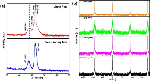
To explore the crystallinity of LSMO:NiO VAN on SAO-buffered STO, standard θ–2θ X-ray diffraction (XRD) has first been characterized, as shown in the upper panel of Figure (a). Only LSMO (002), NiO (002) and SAO (008) peaks can be identified from the film, which indicates the highly textured growth of all the phases in the film along c-direction. The 2θ values of LSMO (002) and NiO (002) are 46.3411° and 44.0287°, which correspond to the d-spacing of 3.916 Å [out-of-plane (OP) tensile strain +1.45% compared with the bulk value of 3.86 Å] and 4.111 Å (OP compressive strain −1.58% as compared with the bulk value of 4.177 Å), respectively. To further explore the in-plane (IP) matching between the VAN layer, buffer layer and substrate, the φ scans of LSMO (111), NiO (111), SAO (444) and STO (111) have been measured and shown in Figure (b), all the four peaks from each material match very well. The matching relationship could be determined as LSMO [001]/NiO [001]/SAO [004]/STO [001] and LSMO [100]/NiO [100]/SAO [400]/STO [100]. Then, to determine the film quality of the freestanding LSMO:NiO film, standard θ–2θ XRD was also carried out as shown in the lower panel of Figure (a), only LSMO (002) (at 46.3133° with d-spacing of 3.918 Å, OP tensile strain +1.5%) and NiO (002) (at 43.7688° with d-spacing of 4.134 Å, OP compressive strain −1.03%) peaks can be identified. Compared to the unreleased film, after being freestanding, the peak of NiO phase shifts slightly to the left, whereas almost no peak shift was observed for the LSMO phase. The reason is that after being released from the substrate, the strain between the film and substrate disappears. However, the vertical strain between the LSMO phase and NiO phase maintains. Furthermore, as LSMO exhibits a larger elastic modulus (562 GPa) [Citation35] than that of NiO (∼185 GPa) [Citation36], no peak shift was observed for LSMO, whereas the NiO peak shifted a little.
Figure 1. (a) Standard θ−2θ XRD scans of the as-deposited film (upper panel) and freestanding nanocomposite film (lower panel); (b) the φ scans of LSMO (111), NiO (111), SAO (444) and STO (111) peaks.
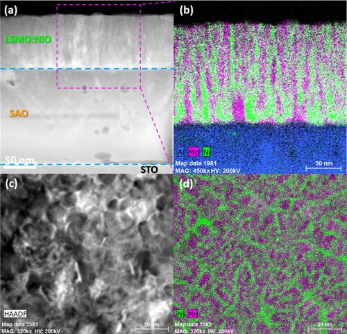
To investigate the microstructure of the LSMO:NiO film, a transmission electron microscopy (TEM) study was conducted, as shown in Figure . Figure (a) is a low-mag scanning transmission electron microscopy (STEM) image with its corresponding energy-dispersive X-ray spectroscopy (EDS) mapping in Figure (b). The thickness of the LSMO:NiO layer can be estimated to be ∼85 nm. Some pores were observed in the SAO layer, which is because it was partially dissolved during TEM sample preparation. Furthermore, the LSMO and NiO nanodomains are vertically aligned on the substrate. Figure (c–d) is the plan view STEM image with its corresponding EDS mapping, a nanomaze-like structure has been observed with distinct separation of the LSMO and NiO phase, which is unlike the vertically aligned nanopillar-in-matrix structure of LSMO:NiO on other substrates [Citation31,Citation34]. The nanomaze-like structure has also been obtained in some other VAN systems [Citation37,Citation38], which results from the lattice matching between the phases in the nanocomposite film and the substrate. The growth mechanism could also be related to the similar surface energy of LSMO, NiO and SAO, which leads to the nucleation and layered growth for both LSMO and NiO phases on SAO. Therefore, both LSMO and NiO nucleate randomly on the SAO surface and form the self-assembled nanomaze-like structure. The exact mechanism is still under further investigation.
Figure 2. Low-mag scanning transmission electron microscopy (STEM) images in (a) cross-sectional and (c) plan view with their corresponding energy-dispersive X-ray spectroscopy (EDS) mapping in (b) cross-sectional and (d) plan view of the LSMO:NiO/SAO/STO sample.
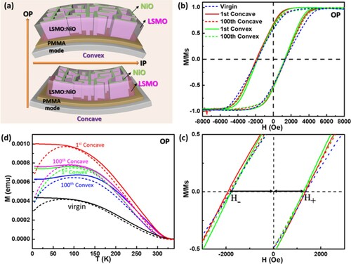
Then, the freestanding LSMO:NiO film was transferred onto flexible PMMA to investigate its EB effect. We selected the flexible substrate for the exploration because of its potential application in portable or wearable devices. Such devices require high material stability and robustness under bending conditions; Therefore, the samples have been attached to a curved plastic mode for the magnetic property measurements, as shown in Figure (a) for both convex and concave conditions. Both OP (perpendicular to film surface) and IP (parallel to film surface) magnetic field (−8000 Oe to 8000 Oe) has been applied to compare its horizontal and perpendicular EB effect. When OP magnetic field has been used, the M–H curves (measured at 10 K) of the freestanding nanocomposite film under bending (convex or concave) conditions after one or hundred times of bending are presented in Figure (b,c) which shows the local regime to identify the difference between H+ and H-. All the M–H curves sustain a left shift, which indicates that the EB effect occurs by the ferromagnetic (FM)–antiferromagnetic (AFM) interface coupling. More importantly, the EB field (HEB = |H+ + H-|/2, H+ and H- represent the magnitude of forward and reverse coercivity) maintains almost the same under bending conditions, which suggests the excellent robustness of such freestanding nanocomposite film even after 100 times of bending. The magnetization as a function of temperature (M–T) under both zero-field cooling (ZFC) and 1000 Oe field cooling (FC) has also been demonstrated to further explore the magnetic performance, as shown in Figure (d). From the results, the Curie temperature (Tc) could be determined to be ∽325 K, which is lower than the Tc of pure LSMO of ∽369 K [Citation15,Citation39]. Such Tc compression could be attributed to the lower degree of magnetic ordering in the composite film [Citation40], as well as the distortion of MnO6 octahedra caused by the lattice-mismatched strain of the vertical LSMO–NiO interface [Citation41]. Another noticeable feature is the bifurcation between the FC and ZFC curves starts at ∽80 K (refers to the irreversible temperature Tirr), which is an indication of magnetic disorder under such temperature and possible spin-glass states, spin clusters, or superparamagnets appear in the film. Furthermore, the maximum M value exists at the temperature of ∽70 K in the ZFC M–T curve refers to the blocking temperature (TB) of NiO nanocrystals, which is lower than Tirr. Future work on detailed magnetic property measurements and analysis could be conducted to further elucidate the magnetic behavior of the nanophases.
Figure 3. (a) Schematic illustrations of the freestanding LSMO:NiO film with convex and concave bending conditions; M–H measured at 10 K of (b) the complete hysteresis loops; (c) local regime to show the difference between H+ and H-; (d) M–T curves of the freestanding LSMO:NiO film with or without bending conditions under OP field; the solid lines are in FC condition and the dotted lines are in ZFC condition.
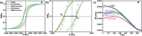
While IP magnetic field has been applied, M–H curve (measured at 10 K) with apparently different shape (Figure (a)) is observed compared with the above OP field situation, owing to the anisotropic nature of the nanocomposite film, which results in anisotropic magnetic response. Meanwhile, an obvious M–H loop shift (shown in Figure (b)) is also achieved under IP field with different HEB values compared with HEB (OP), which will be discussed in the later section. The IP M–T curves (Figure (c)) present similar results compared with the OP M–T curves, except with a slightly lower Tirr of ∽60 K.
Figure 4. M–H (measured at 10 K) of (a) the complete hysteresis loops and (b) local regime to show the difference between H+ and H-; (b) M–T curves of the freestanding LSMO:NiO film with or without bending conditions under IP field, the solid lines are in FC condition and the dotted lines are in ZFC condition.
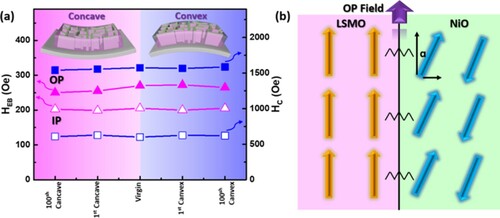
Based on the aforementioned results, the OP and IP HEB and HC (HC = |H+ − H-|/2) values of the LSMO:NiO nanocomposite film with or without bending have been calculated and compared in Figure (a). The OP and IP HEB and HC values can be determined to be HEB (OP)≈260 Oe, HEB (IP)≈200 Oe, HC (OP)≈1500 Oe, HC (IP)≈600 Oe. Such HEB values are close to the LSMO:NiO film on Si31 and larger than the LSMO:NiO film on STO.34 The rough interface of the films in this study and on Si gives rise to increased uncompensated AFM net spins and accordingly increased HEB values compared to the flat interface of the film on STO, which is similar to the same effect that occurs in EB multilayer thin films [Citation42,Citation43]. No obvious difference in HEB and HC values has been observed after bending the film even 100 times, which further reveals the reliability and robustness of the freestanding nanocomposite thin film. In addition, HEB and HC values are larger when applying the OP magnetic field, demonstrating the perpendicular magnetic anisotropy of the nanocomposite film. As illustrated in Figure (b), the OP component of NiO AFM spin is larger than its IP component, which means stronger FM–AFM pinning could be generated when applying OP magnetic field. Overall, the transferable freestanding LSMO:NiO nanocomposite thin film presents a perpendicular EB effect and its physical property is reliable under bending conditions, which suggests that such transfer process is gentle on the films and could be employed for various nanocomposite thin films for flexible device applications.
Figure 5. (a) The HEB and HC values with or without bending conditions; (b) schematic illustration to show the magnetic spin construction at the LSMO/NiO interface.
The advantages of the SAO buffer processed freestanding VAN films are as follows: (1) high-quality epitaxial VAN growth can be established using SAO buffer, and the film quality can be maintained under water dissolution and transfer process; (2) selection of the substrates for future VAN integration can be expanded significantly beyond the conventional oxides. For example, glass substrates, metallic substrates, textiles and others can all be used for substrates for transferred VAN films; (3) more fundamental study on the bending effects of VANs on the physical properties can now be explored using these freestanding VAN films, such as magnetic anisotropy and optical tunability beyond what the previous rigid (e.g. oxides) and semi-flexible substrates (e.g. mica) could offer. Future work in the areas of other VAN systems, especially the recently discovered metal–oxide [Citation44–47] and metal–nitride [Citation25,Citation48,Citation49] VANs, could open up a lot of new nanoscale composite materials selections toward optics and plasmonic devices.
Conclusion
LSMO:NiO nanocomposite thin film has been deposited on water-soluble SAO-buffered STO substrate. Then, freestanding LSMO:NiO film has been obtained by dissolving the sacrificial SAO buffer in water. For the initial demonstration, the freestanding nanocomposite was transferred onto a flexible polymer substrate afterward. No obvious film quality degradation has been observed after aggressive bending test. Magnetic measurements were applied on the transferred LSMO:NiO film with or without bending the flexible substrate. The results show that the HEB and HC values (under both OP and IP field) were maintained nearly the same even after bending for 100 times (i.e. HEB (OP)≈260 Oe, HEB (IP)≈200 Oe, HC (OP)≈1500 Oe, HC (IP)≈600 Oe), revealing the robustness of the freestanding VAN film. Such LSMO:NiO freestanding film also presents OP-preferred magnetic anisotropy owing to the unique vertically aligned nanomaze-like structure. This first freestanding VAN film demonstration opens up great opportunities for many other multifunctional VAN films integration on versatile substrates and for a wide range of applications including spintronics, magnetic data storage, optics, sensors and beyond.
Methods
Target preparation and thin-film growth
SAO and LSMO:NiO nanocomposite targets were prepared by conventional solid-state mixing and sintering process. The targets were used to deposit LSMO:NiO thin film on SAO-buffered STO (001) substrate using a pulsed laser deposition method with a KrF excimer laser (Lambda Physik, λ = 248 nm). The base pressure was below 1 × 10⁻⁶ Torr, during deposition, and the temperature was raised to 700°C with 100 mTorr oxygen inflowing; the laser frequency was controlled at 5 Hz and the target–substrate distance was 4.5 cm. After deposition, the film was cooled in 200 Torr oxygen at a cooling rate of 10°C/min.
Freestanding film transfer process
The deposited sample was inserted in DI water at room temperature for 1 min to dissolve the SAO sacrificial layer and then the freestanding nanocomposite thin film was transferred onto a flexible PMMA substrate.
Microstructure and physical property characterizations
The crystallinity and microstructure of the nanocomposite thin film were characterized by XRD (Panalytical X’Pert X-ray diffractometer) and TEM (FEI Talos-200X) with EDS. Temperature dependence of ZFC and FC magnetization, magnetic hysteresis loops for the transferred freestanding film on a flexible substrate with or without bending were measured by a SQUID magnetometer (MPMS: Quantum Design).
Supplemental Material
Download MS Word (2.7 MB)Acknowledgements
This work was supported by the U.S. National Science Foundation (DMR-1565822 and DMR-2016453). D.Z. and H.W. acknowledge the support from the U.S. Office of Naval Research under contract No. N00014-20-1-2043 for TEM effort. J.H. acknowledges the support from Shenzhen Science and Technology Program (JCYJ20210324133610028), Guangdong Basic and Applied Basic Research Foundation (2019A1515111029).
Disclosure statement
No potential conflict of interest was reported by the author(s).
Additional information
Funding
Reference
- Kacedon DB, Rao RA, Eom CB. Magnetoresistance of epitaxial thin films of ferromagnetic metallic oxide SrRuO3 with different domain structures. Appl Phys Lett. 1997;71:1724–1726.
- Dawber M, Rabe KM, Scott JF. Physics of thin-film ferroelectric oxides. Rev Mod Phys. 2005;77:1083–1130.
- Huang J, Wang H. Effective magnetic pinning schemes for enhanced superconducting property in high temperature superconductor YBa2Cu3O7-x: a review. Supercond Sci Technol. 2017;30:114004.
- Martin LW, Chu YH, Ramesh R. Advances in the growth and characterization of magnetic, ferroelectric, and multiferroic oxide thin films. Mater Sci Eng R. 2010;68:89–133.
- Bao Z, Chen X. Flexible and stretchable devices. Adv Mater. 2016;28:4177–4179.
- Son D, Lee J, Qiao S, et al. Multifunctional wearable devices for diagnosis and therapy of movement disorders. Nat Nanotechnol. 2014;9:397–404.
- Liu Y, He K, Chen G, et al. Nature-inspired structural materials for flexible electronic devices. Chem Rev. 2017;117:12893–12941.
- Koch R. The intrinsic stress of polycrystalline and epitaxial thin metal films. J Phys Condens Matter. 1994;6:9519–9550.
- He M, Ishihara R, Neihof EJ, et al. Large polycrystalline silicon grains prepared by excimer laser crystallization of sputtered amorphous silicon film with process temperature at 100 °C. Jpn J Appl Phys. 2007;46:1245–1249.
- Huang J, Chen L, Jian J, et al. A simplified superconducting coated conductor design with Fe-based superconductors on glass and flexible metallic substrates. J Alloys Compd. 2015;647:380–385.
- Dutta P, Rathi M, Zheng N, et al. High mobility single-crystalline-like GaAs thin films on inexpensive flexible metal substrates by metalorganic chemical vapor deposition. Appl Phys Lett. 2014;105:092104.
- Li CI, Lin JC, Liu HJ, et al. Van der Waal epitaxy of flexible and transparent VO2 film on muscovite. Chem Mater. 2016;28:3914–3919.
- Huang J, Wang H, Wang X, et al. Exchange bias in a La0.67Sr0.33MnO3/NiO heterointerface integrated on a flexible mica substrate. ACS Appl Mater Interfaces. 2020;12:39920–39925.
- Liu HJ, Wang CK, Su D, et al. Flexible heteroepitaxy of CoFe2O4/muscovite bimorph with large magnetostriction. ACS Appl Mater Interfaces. 2017;9:7297–7304.
- Huang J, Wang H, Sun X, et al. Multifunctional La0.67Sr0.33MnO3 (LSMO) thin films integrated on mica substrates toward flexible spintronics and electronics. ACS Appl Mater Interfaces. 2018;10:42698–42705.
- Edler T, Mayr SG. Film lift-off from MgO: freestanding single crystalline Fe-Pd films suitable for magnetic shape memory actuation and beyond. Adv Mater. 2010;22:4969–4972.
- Bakaul SR, Serrao CR, Lee M, et al. Single crystal functional oxides on silicon. Nat Commun. 2016;7:10547.
- Shen L, Wu L, Sheng Q, et al. Epitaxial lift-off of centimeter-scaled spinel ferrite oxide thin films for flexible electronics. Adv Mater. 2017;29:1702411.
- Paskiewicz DM, Sichel-Tissot R, Karapetrova E, et al. Single-crystalline SrRuO3 nanomembranes: a platform for fexible oxide electronics. Nano Lett. 2016;16:534–542.
- Lu D, Baek DJ, Hong SS, et al. Synthesis of freestanding single-crystal perovskite flms and heterostructures by etching of sacrifcial water-soluble layers. Nat Mater. 2016;15:1255–1260.
- Hong SS, Yu JH, Lu D, et al. Two-dimensional limit of crystalline order in perovskite membrane films. Sci Adv. 2017;3:eaao5173.
- Alonso JA, Rasines I, Soubeyroux JL. Tristrontium dialuminum hexaoxide: an intricate superstructure of perovskite. Inorg Chem. 1990;29:4768–4771.
- Park J, Shin JH, Song K, et al. Non-ohmic conduction in exfoliated La0.7Ca0.3MnO3 thin films. Appl Phys Lett. 2020;116:022401.
- Ji D, Cai S, Paudel TR, et al. Freestanding crystalline oxide perovskites down to the monolayer limit. Nature. 2019;570:87–90.
- Huang J, Wang X, Hogan NL, et al. Nanoscale artificial plasmonic lattice in self-assembled vertically aligned nitride-metal hybrid metamaterials. Adv Sci. 2018;5:1800416.
- Zheng H, Wang J, Lofland SE, et al. Multiferroic BaTiO3-CoFe2O4 nanostructures. Science. 2004;303:661–663.
- Huang J, MaCmanus-Driscoll JL, Wang H. New epitaxy paradigm in epitaxial self-assembled oxide vertically aligned nanocomposite thin flms. J Mater Res. 2017;32:4054–4066.
- MacManus-Driscoll JL. Self-assembled heteroepitaxial oxide nanocomposite thin film structures: designing interface-induced functionality in electronic materials. Adv Funct Mater. 2010;20:2035–2045.
- Amrillah T, Bitla Y, Shin K, et al. Flexible multiferroic bulk heterojunction with giant magnetoelectric coupling via van der waals epitaxy. ACS Nano. 2017;11:6122–6130.
- Liu J, Wang X, Gao X, et al. Multifunctional self-assembled BaTiO3-Au nanocomposite thin films on flexible mica substrates with tunable optical properties. Appl Mater Today. 2020;21:100856.
- Huang J, Gellatly A, Kauffmann A, et al. Exchange bias effect along vertical interfaces in La0.7Sr0.3MnO3:NiO vertically aligned nanocomposite thin films integrated on silicon substrates. Cryst Growth Des. 2018;18:4388–4394.
- Kalaswad M, Zhang B, Wang H, et al. Tailorable Fe nanostructures and magnetic anisotropy in (La0.5Sr0.5FeO3)1-x:Fex thin films integrated on SrTiO3 and silicon substrates. Mater Today Adv. 2020;8:100112.
- Ning X, Wang Z, Zhang Z. Temperature-tunable low-field magnetoresistance in La0.7Sr0.3MnO3/NiO nanocomposite films modulated by microstructures. Adv Funct Mater. 2014;24:5393–5401.
- Zhang W, Li L, Lu P, et al. Perpendicular exchange-biased magnetotransport at the vertical heterointerfaces in La0.7Sr0.3MnO3:NiO nanocomposites. ACS Appl Mater Interfaces. 2015;7:21646–21651.
- Huang D, Cheng Y, Liu X, et al. Study of the elastic constants in a La0.6Sr0.4MnO3 film by means of laser-generated ultrasonic wave method. Ultrasonics. 2006;44:e1223–e1227.
- Gaillac R, Pullumbi P, Coudert F. ELATE: an open-source online application for analysis and visualization of elastic tensors. J Phys: Condens Matter. 2016;28:275201.
- Chen A, Zhang W, Khatkhatay F, et al. Magnetotransport properties of quasi-one-dimensionally channeled vertically aligned heteroepitaxial nanomazes. Appl Phys Lett. 2013;102:093114.
- Wang F, Jiang C, Li J, et al. Metal-nitride nanocomposite thin film of nanomaze-like Cu embedded in TiN. Mater Lett. 2021;294:129780.
- Park J, Vescovo E, Kim H, et al. Magnetic properties at surface boundary of a half metallic ferromagnet La0.7Sr0.3MnO3. Phys Rev Lett. 1998;81:1953–1956.
- Ju H, Gopalakrishnan J, Peng J, et al. Dependence of giant magnetoresistance on oxygen stoichiometry and magnetization in polycrystalline La0.67Ba0.33MnOz. Phys Rev B. 1995;51:6143–6146.
- Tian Y, Ding J, Lin W, et al. Anomalous exchange bias at collinear/noncollinear spin interface. Sci Rep. 2013;3:1094.
- Moritz J, Bacher P, Dieny B. Numerical study of the influence of interfacial roughness on the exchange bias properties of ferromagnetic/antiferromagnetic bilayers. Phys Rev B. 2016;94:104425.
- Vafaee M, Finizio S, Deniz H, et al. The effect of interface roughness on exchange bias in La0.7Sr0.3MnO3-BiFeO3 heterostructures. Appl Phys Lett. 2016;108:072401.
- Huang J, Wang H, Qi Z, et al. Multifunctional metal-oxide nanocomposite thin film with plasmonic Au nanopillars embedded in magnetic La0.67Sr0.33MnO3 matrix. Nano Lett. 2021;21:1032–1039.
- Zhang D, Qi Z, Jian J, et al. Thermally stable Au-BaTiO3 nanoscale hybrid metamaterial for high-temperature plasmonic applications. ACS Appl Nano Mater. 2020;3:1431–1437.
- Huang J, Li L, Lu P, et al. Self-assembled Co-BaZrO3 nanocomposite thin films with ultra-fine vertically aligned Co nanopillars. Nanoscale. 2017;9:7970–7976.
- Huang J, Phuah XL, McClintock LM, et al. Core-shell metallic alloy nanopillars-indielectric hybrid metamaterials with magneto-plasmonic coupling. Mater Today. 2021;51:39–47.
- Wang X, Jian J, Zhou Z, et al. Self-assembled Ag-TiN hybrid plasmonic metamaterials with tailorable tilted nanopillar geometry and optical properties. Adv Opt Mater. 2019;7:1801180.
- Huang J, Wang X, Li D, et al. 3D hybrid plasmonic framework with Au nanopillars embedded in nitride multilayers integrated on Si. Adv Mater Inter. 2020;7:2000493.