
 ?Mathematical formulae have been encoded as MathML and are displayed in this HTML version using MathJax in order to improve their display. Uncheck the box to turn MathJax off. This feature requires Javascript. Click on a formula to zoom.
Abstract
Although cross-slip strongly affects the deformation of polycrystalline materials, the phenomenon is rarely studied in twinned face centered cubic (FCC) metals. Here we performed in-situ TEM nanoindentation on a twinned nickel bi-crystal. Multiple pile-ups were generated, with the first dislocations pinned at a coherent twin boundary (CTB) and multiple following dislocations cross-slipping within the matrix. Stress calculation revealed that the cross-slip events are made possible by the CTB, the first dislocations, and the favorable shear stress created jointly by external stress and dislocation interaction. These cross-slip events reduce tip stress and soften the material until inter-grain plasticity is eventually activated.
IMPACT STATEMENT
In-situ TEM nanoindentation reveals the characteristics of dislocation pinning, pile-ups and cross-slip along the twinning boundary in a twinned FCC metal for the first time.
GRAPHICAL ABSTRACT
Introduction
Coherent twin boundaries (CTBs) [Citation1,Citation2] and semi-coherent interfaces [Citation3] in metals affect both their strength and ductility. As CTBs block incoming dislocations, their presence can lead to dislocation pile-ups [Citation4,Citation5]. These pile-ups initially impede deformation of the material by creating an internal stress concentration. However, if the local stress is sufficiently high, other dislocation behaviors are activated to relax the overall stress, enabling further deformation. Numerous investigations have been conducted on the dislocation behaviors encountered with CTBs [Citation6–12]. Most of these studies have focused only on inter-grain behaviors such as dislocation transmission and cross-slip on the CTB. Intra-grain behaviors [Citation13,Citation14] are similarly common stress concentration and relaxation processes. For instance, it has been demonstrated that intra-grain dislocation pile-up and cross-slip creates forward stress and back stress in some heterostructure materials [Citation15,Citation16], strongly affecting their work hardening [Citation17], dynamic recovery [Citation18,Citation19], and strengthening and softening [Citation20]. Despite the above, there are relatively few studies of intra-grain behaviors. In particular, scenarios where dislocations are piled up against a CTB have rarely been studied. As a result, the conditions required for this scenario to occur, and the characteristics this behavior exhibits, are unclear. Similarly, the effect of pile-up and cross-slip on the mechanical behaviors of twinned face centered cubic (FCC) materials in this situation is not well understood.
The paucity of studies reporting on intra-grain behavior is primarily due to a lack of suitable experimental methods. Such techniques must be able to track and characterize dislocations in both the matrix and the twin during deformation, and quantify the internal stress field, rather than just the external load.
In-situ nanoindentation inside a transmission electron microscope (TEM-NanoIN) has been widely adopted to study dislocation-grain boundary interactions in the past [Citation21–23]. However, with the previous TEM nanoindentation platforms, samples are unable to rotate freely around two orthogonal axes during deformation, making it difficult to obtain favorable diffraction conditions. Thus, most dislocations involved in the indentation process are uncharacterized, the configuration of dislocations is unclear, and the corresponding stress field is unknown.
The double-tilt Bestron-ThermoFisher TEM-NanoIN testing system developed recently [Citation24,Citation25] enables real-time quantitative investigation of piled-up dislocations. Hence, in this study, we used this platform to conduct in-situ nanoindentation tests on a twinned nickel bi-crystalline sample. We subsequently performed stress calculations to analyze the factors that facilitated the cross-slip events observed in the indentation tests, for explanation of intra-grain cross-slip in pile-ups, and the role of CTBs in the deformation of FCC materials. This analysis also helps clarify the effect of back stress and forward stress on the mechanical stability of heterostructure materials.
Materials and methods
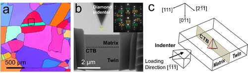
In this study, we used a polycrystalline nickel cylinder (99.995% purity) as the raw material for nanoindentation tests. The workflow for testing is described as follows. First, we obtained the grain orientation information of the cylinder using electron back scattering diffraction (EBSD), to locate and characterize the CTBs (Figure (a)). We then fabricated a twinned sample with the typical H-bar geometry from the region marked by the black frame in Figure (a). Here, we used focused ion beam (FIB) milling for fabrication to assure a minimum sample thickness of ∼190 nm, such that thin foil effects on dislocation nucleation and movement are avoided. This was conducted using the Helios-600i dual beam FIB-SEM (scanning electron microscope) system (ThermoFisher). Following fabrication, the sample was mounted on a MEMS device [Citation26] on a Bestron-ThermoFisher TEM-NanoIN double-tilt TEM holder [Citation24], then inserted into a Titan ETEM (ThermoFisher). Indentation was conducted along the sample’s direction at a rate of ∼0.6 nm/s. The setup of the TEM-NanoIN test is shown in Figure (b). The inset is the selected area electron diffraction (SAED) pattern of the sample, containing diffraction spots for the matrix (yellow) and the twin (green). The crystallographic relationships within this setup are illustrated in Figure (c).
Figure 1. (a) EBSD map of the surface of the nickel cylinder used in indentation tests. The black frame marks the CTB selected for sample fabrication. (b) The setup of TEM-NanoIN test. The inset shows the SAED of the sample. (c) Crystallographic relationships in the experimental setup.
Results
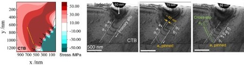
During the indentation tests, the sample was viewed under bright field with g = [111] (inset in Figure (a)), to ensure that dislocations in both the matrix and the twin could be observed clearly. Here, we noted four dislocations (a1–a4) glide on the or the
plane. These dislocations gradually piled up against the CTB, with a1 eventually pinned at the CTB (Figures (a)–(c)). With further indentation, we observed the nucleation of three dislocations (b1, b2, and b3) in a parallel plane. As these dislocations propagated, a2 moved rapidly to the position marked by the dashed circle in Figure (d). This propagation occurred along the direction parallel to
(denoted by the dashed green arrow), indicating that a2 had cross-slipped and glided upward onto the
plane. Slips were activated on a total of five parallel planes upon further indentation, as shown in Figure (e). From this, we noted that the first dislocation on each plane (a1, b1, c1, d1 and e1) reached and was pinned at the CTB, as corroborated by the dark field image in Figure (f). The inclined streaks in this image are suggestive of the highly-strained defect regions near the CTB, caused by the pile-ups of dislocations, and the subsequent dislocations coming from the indenter. Multiple parallel cross-slip traces appeared along the direction parallel to the
plane (Figure (h)), indicating the occurrence of abundant cross-slip events following the initial dislocations within the matrix grain, as schematically shown in Figure (i). No sign of dislocation transmission was observed on the CTB or in the twin during the indentation process, indicating either that no inter-grain stress relaxation process occurred prior to intra-grain cross-slip, or the magnitude of the forward stress did not reach the resolved shear stress level required to nucleate dislocations across the twin boundary [Citation15,Citation16]. Figure (g) shows a stereographic projection and Thompson’s tetrahedron for explanation of the cross-slip events. In these images, the primary slip plane (
or
) is highlighted in red, and the cross-slip plane
is highlighted in green.
Figure 2. (a–e) Sequential TEM images showing abundant intra-grain cross-slip of dislocations piled up against a CTB. The labels at the top right corner of each image correspond to the indentation depth. (f) Dark-field TEM image of the area in the yellow frame in (e) viewed under . (g) Stereographic projection and Thompson’s tetrahedron illustrating the crystallographic relationships of the primary slip and cross-slip planes. (h) TEM image of the sample after retraction of the indenter. The cross-slip traces are more evident, as shown by the green dashed arrows. (i) Schematic illustration of the origin of the multiple cross-slip events in (e).
![Figure 2. (a–e) Sequential TEM images showing abundant intra-grain cross-slip of dislocations piled up against a CTB. The labels at the top right corner of each image correspond to the indentation depth. (f) Dark-field TEM image of the area in the yellow frame in (e) viewed under g=[2¯11]. (g) Stereographic projection and Thompson’s tetrahedron illustrating the crystallographic relationships of the primary slip and cross-slip planes. (h) TEM image of the sample after retraction of the indenter. The cross-slip traces are more evident, as shown by the green dashed arrows. (i) Schematic illustration of the origin of the multiple cross-slip events in (e).](/cms/asset/dbd6aa0e-90a6-4ee2-9c50-37c4a5e2b5e0/tmrl_a_2065892_f0002_oc.jpg)
The nanoindentation test conducted in this study was performed at room temperature. Hence, as there was no thermal activation, we consider the intra-grain cross-slip events described above to be purely stress driven. We thus analyze the stress conditions in the following sections, to elucidate the role of the contributors involved in these cross-slip events (i.e. the indenter, the CTB, and the dislocations), their competition with inter-grain processes, and their effect on the strength and ductility of twinned nickel.
Stress analysis and calculation
Under an indenter, the dislocations gliding in pile-ups are subject to both the stress generated by the indenter, and the interacting stress from other dislocations and twin boundaries. Molecular dynamics simulations [Citation27] indicate that the CTB principally acts as a kinematic barrier to approaching dislocations, with no obvious elastic repulsion. Therefore, the influence of the CTB on the shear stress is not considered here.
In this study, we employed isotropic elasticity theory in our stress analysis, as in Ref. [Citation28]. The dislocations shown in Figure are curved, indicating that they contain both screw and edge components. To simplify the stress analysis, we only consider screw components. However, the procedure for estimating edge components is similar to the description below (the tensile stress of the edge components will be approximately 1.5 times that of the screw components).
Analysis of the stress generated by the indenter was conducted in the sample coordinate system (C1, Figure (b)). This stress can be expressed by nine tensors in the Hertzian field [Citation29]. Because the sample is considerably thinner along the z-axis than the y axis (Figure (a)), the stress tensors acting on the z plane are assumed to be relaxed when the sample is indented along the y direction. Therefore, there are only four non-zero stress components, σxx, σyy, τxy and τyx, as shown in Figure (b). The resolved shear stress imposed by the indenter on the primary and cross-slip systems, denoted as τi,p and τi,c respectively, are the resultant stress of the resolved shear component of the tensors along b on the primary and cross-slip planes, respectively.
Figure 3. (a) Schematic illustration of indentation in sample coordinates (C1). (b) Definition of stress tensors in a unit cell under indentation in C1 coordinates. (c) Schematic illustration of the relationship between the slip coordinate system (C2) and C1. (d and e) Stress fields created by a dislocation on primary and cross-slip systems in C1.
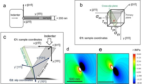
The elastic interactions between the dislocations are analyzed in the slip coordinate system (C2, Figure (c)). These interactions contain two shear tensors for the screw components [Citation30]. The shear component acting on the primary system, τd, p, and the shear component acting on the cross-slip system, τd, c, can be obtained by resolving the two tensors on the corresponding systems. Detailed derivation of τi, p, τi, c, τd, p and τd, c is included in the supplementary material. The stress fields created by dislocations on the primary and cross-slip systems in C1 are shown in Figures (d) and (e), respectively. The collective stress field can be obtained by superimposing the stress field generated by each dislocation on each other. Hence, the resultant shear stress acting on the primary and cross-slip systems, τp and τc, can be expressed in terms of the stresses created jointly by the indenter and the dislocations, as:
(1)
(1)
(2)
(2)
In addition to the above, a dislocation moving in a crystal experiences lattice friction opposite to its Burgers vector. This friction is approximately 10 MPa for glide of the screw component of a dislocation in Ni [Citation31,Citation32]. Although the tensile stress of an edge dislocation is higher than that of a screw dislocation, both quantities are of the same order of magnitude. The stress required for cross-slip of piled-up dislocations in Cu [Citation33], another typical FCC metal, is slightly higher than the lattice friction of dislocations in Cu [Citation32]. Hence, in this study, we defined the critical resolved shear stress, τcr, for both dislocation glide and cross-slip in Ni as 10 MPa.
Based on the above analysis, we conducted detailed stress calculation for explanation of the upward intra-grain cross-slip of a2 (Figure (a)). To elucidate the influence of different contributors to the cross-slip, we calculated the distributions of τp and τc in five different scenarios (S1–S5), as summarized in Table . S1 considers only the contribution of the indenter, while S2–S4 examine the importance of different groups of dislocations. S5 takes all discernable contributors into consideration, to simulate the actual case observed in tests.
Figure 4. Analysis of the cross-slip of a2. (a) TEM image taken just prior to the cross-slip of a2. The slip planes and dislocations involved in cross-slip are denoted by solid lines and '⊥' signs, respectively. The CTB is marked as a red line. (b)–(e) Maps of stress distributions calculated for scenarios S1–S5 (in each map, a2’s potential direction of motion is indicated by the green dashed arrow. The location of the cross-slip (CS) point in experiments is indicated by the green '⊥' symbol.): (b) Distribution of τp in Region I (marked by the black box in (a)); (c) Distribution of τc in Region II marked by the red box in (a); (d) Distribution of τc in Region I; (e) Distribution of τc in Region II (f) Comparison of the stress profiles in the vicinity of the CS point for each scenario.
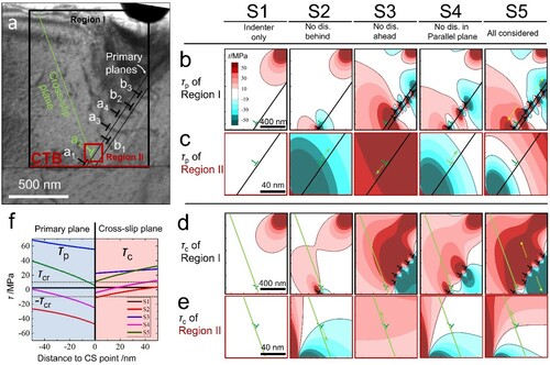
Table 1. Summary of scenarios considered in stress calculation.
In each scenario, we calculated the stress in a region containing all contributors (termed Region I, the black box in Figure (a)), and in the region in the vicinity of the cross-slip (termed Region II, the red box in Figure (a)), resulting in a total of 20 stress maps. These maps are displayed as a 4×5 matrix in Figures (b)–(e), summarizing the distributions of τp and τc in S1–S5. Figure (f) is a comparison of τp and τc in the vicinity of the cross-slip (CS) point for all the different scenarios.
The three colors in the stress maps indicate the relationship of the shear stress in the given region to the critical resolved shear stress τcr. Regions highlighted in red indicate that the shear stress is greater than τcr, regions highlighted in blue indicate that the shear stress is less than −τcr, and regions highlighted in white indicate that the shear stress is between −τcr and τcr. The dislocations’ directions of motion in the different regions are indicated by the yellow arrows in the 5th column of Figures (b) and (d). The following conditions must be satisfied simultaneously for upward intra-grain cross-slip to occur:
(3)
(3)
(4)
(4)
Based on the above, the CS point should be in a location where the white region of the τp map coincides with the red region of the τc map.
In the 1st column in Figures (b)–(e), both τp and τc decay rapidly to below τcr. Hence, the CS point (the green ‘⊥’ symbol) resides in the immobile (white) region of the maps, indicating that the stress caused by the indenter alone (i.e. the external stress) is not able to move a2 on either the primary or cross-slip plane. The 2nd to 5th columns of Figure (d) depict τc fields favorable for motion along the cross-slip plane, indicating that the appearance of surrounding dislocations promotes the upward glide of a2. However, closer examination of the stress distribution in Region II shows that τp and τc satisfy both Equations (3) and (4) only in S5 (the 5th column of Figures (c) and (e)). In this scenario, the magnitudes of the stresses favor the upward intra-grain cross-slip of a2, which is consistent with the experimental result. Without the dislocation ahead (S3, the 3rd column of Figures (c) and (e)), both τp and τc are greater than τcr, such that a2 should glide downward in the primary plane. Without the dislocations behind (S2, the 2nd column of Figures (c) and (e)), both τp and τc are smaller than −τcr, such that a2 should glide upward in the primary plane. Similarly, without the dislocations in the parallel slip plane, (S4, the 4th column of Figures (c) and (e)), a2 should glide upward in the primary plane, as τp is less than −τcr and −τcr<τc< τcr. This summary indicates that cross-slip occurred because a1 created a low τp region ahead of a2 that elastically blocked its propagation in the primary system, while the combination of the dislocations in the two primary planes and the indenter collectively created a large enough stress to enable the upward cross-slip and subsequent propagation of a2. The same conclusion can be drawn from the comparison in Figure (f), as only the curve for S5 satisfies both Equations (3) and (4).
Although the CTB itself does not repel dislocations, it contributes to cross-slip by kinematically blocking the propagation of a1. This blockage allows the dislocation to elastically repel a2; without the CTB, a1 should have moved forward because of the high τp (94.3 MPa, obtained by calculation), and it would have been unable to stop subsequent dislocations effectively. This hypothesis is corroborated by Figures (e) and (f), which show that the first dislocations of the five parallel pile-ups are pinned at the CTB, while multiple subsequent dislocations are deflected to the cross-slip plane. We infer cross-slip based on the appearance of increasing numbers of traces parallel to the cross-slip plane of a1 as indentation proceeded, as shown by Figures (a)–(e) and the Supplementary Movie. Hence, we surmise that cross-slip is made possible by three factors: a kinematic barrier (the CTB), an elastic barrier (a1), and a favorable τc field, created jointly by external stresses and internal interaction between dislocations.
The competition between the intra-grain cross-slip (from back stress) and inter-grain processes (from forward stress) can also be explained using stress calculation. Inter-grain interaction between the CTB and the first dislocation in the pile up can only be activated when the τp acting on the first dislocation exceeds a certain magnitude. Through simulation, Jin et al. [Citation9] determined that the lowest τp required to activate inter-grain processes in Ni during 60° dislocation-CTB interaction is ∼285 MPa, much higher than the τp acting on a1 (94.3 MPa) when a2 cross-slipped. Therefore, a2 cross-slipped prior to the onset of inter-grain processes.
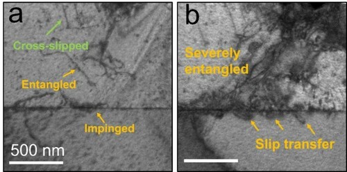
The reduction in stress following the intra-grain cross-slip of a2 at the tip of the pile-up (i.e. a1) can also be quantified, for characterization of cross-slip as a stress-relaxation process. The τp acting on a1 after the cross-slip was 44.6 MPa. This value is far below the minimum required for the onset of inter-grain processes, and 52.7% lower than the value of τp before cross-slip (94.3 MPa). Hence, multiple intra-grain cross-slip events were activated prior to inter-grain processes in the current experimental setup (Figure (g)). These events collectively lower the stress concentration in the pile-up and postpone plastic flow across the CTB, leading to a decrease in strain hardening [Citation17,Citation19]. However, with further deformation, this abundance of intra-grain cross-slip events activates other strengthening mechanisms. Many of the cross-slipped dislocations eventually stopped after gliding, as shown in Figure (a), and suppressed other dislocations in primary planes from cross-slipping. This suppression increases the possibility of dislocation entanglement (Figure (a)), which also leads to strain hardening [Citation34,Citation35]. As deformation proceeds, dislocations entangle more severely and eventually activate inter-grain processes, allowing plastic flow across the CTB (Figure (b)).
Figure 5. (a) Dislocation entanglement in the sample following further indentation. (b) Slip transfer after severe entanglement.
As a blocker to impede and interact with moving dislocations to strengthen materials and as a dislocation source to emit/nucleate dislocations, TBs have similar roles in parallel with grain boundaries (GBs). While, regarding atomic structures of a blocker, note that GBs could have more variants than twin boundaries, such as size effects between neighboring grains by heterogeneous design [Citation16], flexible mis-orientations for neighboring grains [Citation36] and versatile grain boundary structures with atomic and nano scale steps [Citation37]. TB and GB have similarities while they keep their own uniqueness. In the future, it is worthwhile to explore if these dislocation-TB interaction and pile-up phenomena (pinning of the first dislocation, line-up of the pinned dislocation arrays, cross-slip and reversal movement of dislocations by back stress, etc.) can apply to regular GBs. Integrating TB and GB could be promising to develop strong yet ductile materials without ends [Citation16, Citation38].
Conclusions
In this study, we investigated intra-grain cross-slip of dislocations piled up against a CTB using a nickel bi-crystal. This investigation was facilitated by our use of the Bestron-ThermoFisher system, which enables free rotation of a sample in two orthogonal axes during in-situ nanoindentation in TEM. During this indentation, the first dislocation in each pile-up was pinned at the CTB, and multiple subsequent dislocations cross-slipped within the matrix prior to inter-grain processes. Stress calculation revealed that the cross-slip events were made possible by the presence of a kinematic barrier (the CTB), an elastic barrier (the 1st dislocation), and a favorable shear stress created jointly by external stress and internal interaction between dislocations. These cross-slip events reduced the stress exerted by the tip, and softened the material. The abundance of intra-grain cross-slip events that occurred as indentation continued led to dislocation entanglement, which strengthened the material until inter-grain processes were eventually activated. These results clarify the characteristics of intra-grain cross-slip of piled-up dislocations, and enhance the understanding of the strengthening and softening effects of CTBs in FCC materials.
Supplemental Material
Download Zip (18.9 MB)Disclosure statement
No potential conflict of interest was reported by the author(s).
Additional information
Funding
References
- Sansoz F, Lu K, Zhu T, et al. Strengthening and plasticity in nanotwinned metals. MRS Bull. 2016;41(4):292–297.
- Lu K, Lu L, Suresh S. Strengthening materials by engineering coherent internal boundaries at the nanoscale. Science. 2009;324(5925):349–352.
- Shao S, Wang J, Beyerlein IJ, et al. Glide dislocation nucleation from dislocation nodes at semi-coherent {1 1 1} Cu–Ni interfaces. Acta Mater. 2015;98:206–220.
- Kacher J, Robertson IM. Quasi-four-dimensional analysis of dislocation interactions with grain boundaries in 304 stainless steel. Acta Mater. 2012;60(19):6657–6672.
- Issa I, Joly-Pottuz L, Amodeo J, et al. From dislocation nucleation to dislocation multiplication in ceramic nanoparticle. Materials Research Letters. 2021;9(6):278–283.
- Zhu YT, Wu XL, Liao XZ, et al. Dislocation–twin interactions in nanocrystalline fcc metals. Acta Mater. 2011;59(2):812–821.
- Lu L, Zhu T, Shen Y, et al. Stress relaxation and the structure size-dependence of plastic deformation in nanotwinned copper. Acta Mater. 2009;57(17):5165–5173.
- Sangid MD, Ezaz T, Sehitoglu H, et al. Energy of slip transmission and nucleation at grain boundaries. Acta Mater. 2011;59(1):283–296.
- Jin Z-H, Gumbsch P, Albe K, et al. Interactions between non-screw lattice dislocations and coherent twin boundaries in face-centered cubic metals. Acta Mater. 2008;56(5):1126–1135.
- Zhu YT, Liao XZ, Wu XL. Deformation twinning in nanocrystalline materials. Prog Mater Sci. 2012;57(1):1–62.
- Li N, Wang J, Misra A, et al. Twinning dislocation multiplication at a coherent twin boundary. Acta Mater. 2011;59(15):5989–5996.
- Wang J, Zhou Q, Shao S, et al. Strength and plasticity of nanolaminated materials. Materials Research Letters. 2017;5(1):1–19.
- Basinski ZS, Mitchell TE. Stresses on secondary systems due to piled-up groups of dislocations of arbitrary orientation. Philos Mag. 1966;13(121):103–114.
- Yu W, Wang Z. Interactions between edge lattice dislocations and Σ11 symmetrical tilt grain boundaries in copper: A quasi-continuum method study. Acta Mater. 2012;60(13-14):5010–5021.
- Yang M, Pan Y, Yuan F, et al. Back stress strengthening and strain hardening in gradient structure. Materials Research Letters. 2016;4(3):145–151.
- Zhu Y, Wu X. Perspective on hetero-deformation induced (HDI) hardening and back stress. Materials Research Letters. 2019;7(10):393–398.
- Rao SI, Dimiduk DM, El-Awady JA, et al. Activated states for cross-slip at screw dislocation intersections in face-centered cubic nickel and copper via atomistic simulation. Acta Mater. 2010;58(17):5547–5557.
- Malka-Markovitz A, Mordehai D. Cross-slip in face-centered cubic metals: A general escaig stress-dependent activation energy line tension model. Philos Mag. 2018;98(5):347–370.
- Xu S, Xiong L, Chen Y, et al. Shear stress- and line length-dependent screw dislocation cross-slip in FCC Ni. Acta Mater. 2017;122:412–419.
- Armstrong RW. Hall–petch description of nanopolycrystalline Cu, Ni and Al strength levels and strain rate sensitivities. Philos Mag. 2016;96(29):3097–3108.
- Ohmura T, Minor AM, Stach EA, et al. Dislocation–grain boundary interactions in martensitic steel observed through in situ nanoindentation in a transmission electron microscope. J Mater Res. 2011;19(12):3626–3632.
- Liu Y, Jian J, Chen Y, et al. Plasticity and ultra-low stress induced twin boundary migration in nanotwinned Cu by in situ nanoindentation studies. Appl Phys Lett. 2014;104(23):231910.
- Bufford D, Liu Y, Wang J, et al. In situ nanoindentation study on plasticity and work hardening in aluminium with incoherent twin boundaries. Nat Commun. 2014 Sep 10;5:4864.
- Han X, Zhang J, Mao S, et al. inventors; Beijing University of Technology, assignee. Double-tilt sample holder for transmission electron microscope. Patent US10103000B2. 2018 Oct 16.
- Han X, Li Z, Mao S, et al. inventors; Beijing University of Technology, assignee. A double-tilt in-situ nanoindentation platform for transmission electron microscope. Patent US10410822B2. 2019 Sep 10.
- Wang X, Mao S, Zhang J, et al. MEMS device for quantitative in situ mechanical testing in electron microscope. Micromachines (Basel). 2017;8(2):31.
- Zhang J, Zhang H, Ye H, et al. Twin boundaries merely as intrinsically kinematic barriers for screw dislocation motion in FCC metals. Sci Rep. 2016 Mar 10;6:22893.
- Hazzledine PM, Hirsch PB. A critical examination of the long-range stress theory of work-hardening. Philos Mag. 1967;15(133):121–159.
- Feng G, Qu S, Huang Y, et al. An analytical expression for the stress field around an elastoplastic indentation/contact. Acta Mater. 2007;55(9):2929–2938.
- Volterra V. Sur l’équilibre des corps élastiques multiplement connexes. Ann Sci Ecole Norm. 1907;24(24):401–517.
- Windle AH, Smith GC. The effect of hydrogen on the plastic deformation of nickel single crystals. Met Sci J. 1968;2(1):187–191.
- Chowdhury PB, Sehitoglu H, Rateick RG. Predicting fatigue resistance of nano-twinned materials: part I – role of cyclic slip irreversibility and peierls stress. Int J Fatigue. 2014;68:277–291.
- Ramírez BR, Ghoniem N, Po G. Ab initiocontinuum model for the influence of local stress on cross-slip of screw dislocations in fcc metals. Physical Review. Part B. 2012;86(9):094115.
- Madec R, Devincre B, Kubin LP. Simulation of dislocation patterns in multislip. Scr Mater. 2002;47(10):689–695.
- Hussein AM, Rao SI, Uchic MD, et al. Microstructurally based cross-slip mechanisms and their effects on dislocation microstructure evolution in fcc crystals. Acta Mater. 2015;85:180–190.
- Wang L, Zhang Y, Zeng Z, et al. Tracking the sliding of grain boundaries at the atomic scale. Science. 2022;375(6586):1261–1265.
- Wang L, Guan P, Teng J, et al. New twinning route in face-centered cubic nanocrystalline metals. Nat Commun. 2017;8(1):1–7.
- Huang Q, Yu D, Xu B, et al. Nanotwinned diamond with unprecedented hardness and stability. Nature. 2014;510(7504):250–253.