
Abstract
Reinforcements in metal composites are usually dispersed at grain boundaries. We here show that the rapid solidification during laser additive manufacturing enables the spontaneous engulfment of reinforcing particles inside aluminum grains, which helps to decouple the stress concentration induced by grain boundaries and reinforcements. The additively manufactured TiB2-Al composite possesses 30% increase in tensile strength and nearly tripled ductility as compared with composite obtained by the traditional method. Our experimental investigations indicate that the intragranular dispersion of particles not only inhibits crack nucleation but also promotes strain hardening, leading to the remarkably enhanced mechanical properties.
GRAPHICAL ABSTRACT
IMPACT STATEMENT
Metal composite with intragranular dispersion of reinforcing particles can be achieved through additive manufacturing, which alleviates stress concentration and possesses much-improved ductility.
1. Introduction
When hard and stiff non-metallic particle incorporates into metals and alloys, the resulted materials, termed as metal matrix composites, are possible to achieve properties beyond their individual components [Citation1–3]. Some light metal matrix composites (e.g. Al and Mg matrix composites) are able to achieve higher specific strength and modulus than almost all structural metals or alloys [Citation4,Citation5], making them ideal substitutes for heavier metals in such diverse applications as automotive, aircraft and aerospace industries. However, high-strength metal composites are prone to be fractured at small strains upon tensile deformation [Citation6]. Such a strength–ductility paradox is an intrinsic obstacle for the use of these materials in currently targeted lightweight-demand industries.
The intergranular distribution of reinforcements in composites is one of the key reasons for the loss of ductility. Grain boundary (GB) is a source of stress concentration during deformation; while reinforcements show tendencies to distribute along GBs due to the large interfacial energy [Citation7–9]. This intergranular distribution intensifies the already strong stress concentration at GBs, causing early crack initiation and failure of the composites. Current solution normally uses nanosized reinforcements to reduce stress localization at GBs, but nanosized reinforcements are easy to agglomerate and could not reach high contents (usually less than 5%). An alternative approach is to design composites with special arrangements of reinforcements; for example, two-dimensional lamella [Citation10,Citation11] and three-dimensional continuous network [Citation12–14]. These architectural design strategies could promote stress re-distribution and retard crack propagation, thereby benefiting the improvement of ductility [Citation10–14]. However, the delicate microstructural control usually requires complex processing procedures and reinforcements are still located at GBs. Therefore, developing effective solutions to alleviate stress concentration and the associated early failure in composites still remains a fundamental challenge.
Theoretically, for conventional fabrication methods of metal matrix composites (e.g. casting), particle distributions are governed by the interaction between the solidifying interface and particles [Citation15]. Particles could easily be pushed by the solid/liquid interface when the solidification front moves slowly, and are finally entrapped at dendrite (or grain) boundaries. Solutions must be developed to incorporate reinforcing particles inside metal grains, in order to decouple the stress concentration induced by GBs and reinforcements. Here, we used selective laser melting (SLM) to introduce intragranular dispersion structure in metal composites to achieve this goal. The rapid solidification during SLM renders high solidification front velocity (on the scale of m/s [Citation16]), allowing for the spontaneous engulfment of reinforcing particles inside metal grains in a single print. Nanoparticles have been widely employed as nucleants as well as grain growth inhibitors to promote equiaxed grain structure during SLM [Citation17], thus these nanoparticles are naturally distributed at GBs in the as-built composite. We here employed micron-sized reinforcing particles instead to restrain heterogeneous grain nucleation and promote particle intragranular incorporation. Taking TiB2-reinforced Al matrix composite as a model material, our experiments and modeling reveal that the rapid solidification feature of SLM enables the spontaneous engulfment of TiB2 particles inside Al grains, which helps to decouple the stress concentration induced by GBs and reinforcements. As a result, the newly developed composite demonstrates an improved tensile strength (∼30%) and nearly tripled ductility as compared to composite obtained from the conventional powder metallurgy (PM) method. Our strategy broadens the design space for composite microstructures via SLM, which may lead to mechanical properties that are unparalleled by the traditional fabrication routes.
2. Theoretical background
To realize intragranular dispersion of reinforcing particles upon solidification, we consider models that are based on force analysis to estimate the critical solidification rate for particle engulfment. The general physics of these models, as illustrated in Figure (a), is depicted in the following:
From a thermodynamic viewpoint, the repulsion of particle by the solidification front (FI in Figure (a)) is associated with a change of free energy [Citation18–20]. The magnitude of repulsive force is dependent either on the interfacial energy change or on the inter-atomic interaction.
The main factor that prevents the particle from being pushed freely is a viscous drag force (denoted as FD in Figure (a)). It can be treated mathematically with a modified version of the classical Stokes’ equation [Citation21]. It is a function of the melt viscosity, particle size and velocity.
The maximum velocity criterion is invoked to balance the repulsive and attractive forces (Figure (b)) [Citation16]. Particles can be pushed below and captured above this critical velocity (Vc).
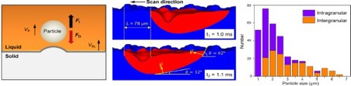
Figure 1. Theoretical analysis of particle engulfment in metal composites by SLM. (a) Schematic of particle motion. FI and FD stand for repulsive and drag force, respectively. VSL and VP are velocities of solidification front and particle motion, respectively. Gravity and buoyancy are not shown due to their small values. (b) The plot of net force as a function of VSL. Vc is critical pushing velocity. (c) The dependence of Vc on particle radius (R). The size ranges of TiB2 particles used in this work are shown. (d) Modeling results on VSL calculation. VSL = V sinθ. V is scanning speed (L/Δt). SD means scan direction. (e) The simulated 3D-temperature gradient profile. X, Y and Z are scan direction, transverse direction and sample building direction, respectively. Inset shows a schematic of melt flow during SLM.
We estimated Vc for our TiB2-Al composite with the generally adopted models. They are Uhlmann–Chalmers–Jackson (UCJ) model [Citation22], Chernov–Temkin–Mel’nikova (CTM) model [Citation23], Shangguan–Ahuja–Stefanescu (SAS) model [Citation24] and Stefanescu model [Citation21] (see Text S1 in Supplementary Materials for more calculation details). As shown in Figure (c), different models all suggest that Vc decreases with particle size, but its absolute value differs significantly. This is likely associated with the different assumptions for these models [Citation16]. In spite of the differences in physical origins, the predicted Vc is small (less than 3 mm/s, Figure (c)). In the following, we will show that the intragranular engulfment of TiB2 particles can be achieved through the rapid solidification during SLM.
3. Results and discussion
We first developed a high-fidelity modeling framework to estimate the melting/solidification behavior upon SLM [Citation25,Citation26]. The modeling delivers 3D temperature, velocity and other data in our composites based on real physical parameters and printing conditions (see Text S2 for modeling details). In particular, the solidification rate is described using the well-known relationship, VSL = R/G; where R is the cooling rate and G is the temperature gradient [Citation16]. As shown in Figure (d), our modeling results reveal that the solidification rate upon SLM ranges from 0.18 m/s to 0.46 m/s. These values are two to five orders of magnitude higher than the estimated critical velocity (as displayed in Figure (c)), suggestive of the spontaneous engulfment of TiB2 particles. In addition to facilitating particle embedding, SLM also demonstrates the capacity to disperse particles uniformly. As displayed in Figure (e), large thermal gradient is produced in melt pool, which creates macroscopic Marangoni vortexes. These macroscopic flow vortexes drag TiB2 particles to migrate in the melt, rendering a dense and uniform distribution of reinforcing particles in the as-built composite [Citation26].
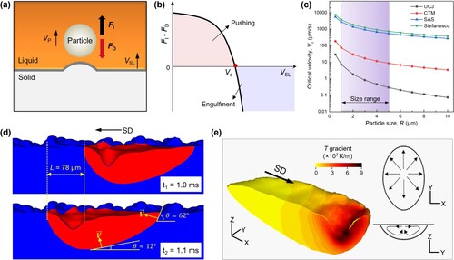
Figure (a) shows the electron backscatter diffraction (EBSD) phase map of the SLM TiB2 (15 vol.%)-Al composite (the fabrication and characterization details can be found in Supplementary Materials). A large proportion of TiB2 particles are intragranularly distributed, as desired. The as-built samples are composed of large columnar grains, which are oriented parallel to the build direction. This is a typical grain morphology associated with the directional heat flux in SLM [Citation27]. Grains have a mean size value of about 20 µm, most of which show local misorientations inside, as evidenced in the kernel average misorientation (KAM) map (Figure S1). We highlight the importance of SLM to achieve the intragranular dispersion by comparing samples fabricated with PM. Figure (b) is a representative EBSD image of the PM sample, revealing that the majority of TiB2 particles are intergranularly distributed. Further deformation (cold rolled by 90%) is also unable to achieve the intragranular dispersion (Figure (c)), although grains are refined from 15.7 µm to 5.1 µm. Specifically, the statistical histogram in Figure (d) indicates that a number fraction of ∼54% particles are intragranularly dispersed in the SLM composite, yet larger particles are prone to be distributed at GBs. We envision this particle-size dependent distribution might be associated with the nucleation process: at a preferential site such as a TiB2 particle (usually treated as a grain refiner in Al), the effective surface energy is lower, thus diminishing the free energy barrier and facilitating Al nucleation [Citation28,Citation29]. The large particle could have higher probability for nucleation due to the large surface area, which facilitates the particle to reside at GB when grain coalesces. Quantitative chemical analysis at TiB2/Al interface using atom probe tomography (APT) indicates that the diffusion of atoms is constrained within 5 nm across the interface, and there are no chemical reactions occurred (Figure (e)). By making use of proximity histograms, we estimate the composition of reinforcing particles in the as-built composite to be 32.7 ± 1.3 at% Ti and 67.1 ± 2.1 at% B, also indicating that there is no decomposition or melting of TiB2 particles upon SLM. The formation of a clean and sharp TiB2/Al interface is due to the fact that the melting/solidification process is extremely fast, which suppresses the diffusion reaction kinetics. We further made an in-depth analysis of the crystallographic relationship between TiB2 and Al matrix (Figure ). Figure (a,b) is the corresponding inverse pole figure of SLM TiB2-Al composite, showing the orientations of Al matrix parallel to the [0001]TiB2 direction. Interestingly, for the intragranularly dispersed TiB2 particles, 6 of the 173 (3.5%) display [0001] direction that is within 10° of the [111]Al direction, and 31 of the 173 (17.9%) have the [0001] direction within 10° of the [001]Al direction. That is, there are no preferred crystallographic orientation relationships between the engulfed TiB2 particles and Al matrix. Particles at GBs also show no systematic relationships, as revealed in Figure (b). These observations are contrary to the conventional TiB2-Al composites, where TiB2 and Al are shown to have a favorable crystallographic relationship of (0001)TiB2//(111)Al or (0001)TiB2//(001)Al [Citation28,Citation30]. Therefore, the solidification rate during SLM is so high that very limited time is allowed for the particles to migrate in the melt, impeding the achievement of a low-energy crystallographic relationship.
Figure 2. Microstructures of as-built TiB2-Al composites. Both SLM and PM TiB2-Al composites possess relative density of larger than 99.5%. (a) EBSD image showing the distribution of TiB2 particles (colored in green, 15 vol.%) in SLM composite. High-angle grain boundaries (HAGBs) with misorientation larger than 10° are superimposed. (b) EBSD image of comparing PM TiB2 (15 vol.%)-Al composite. The non-identified regions are shown in black. (c) EBSD image of PM composite after cold rolling. (d) Histogram showing the size distribution of TiB2 particles and their locations either in grain interiors or at GBs, as measured by EBSD. (e) A typical APT slice (thickness 10 nm) showing the atomic distributions across the TiB2-Al interface. The right panel shows the corresponding 1D compositional profiles.
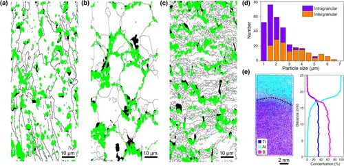
Figure 3. Crystallographic relationship between TiB2 and Al in SLM TiB2-Al composite. (a) and (b) are inverse pole figures showing the orientation of Al matrix parallel to the [0001] direction of the intragranularly and intergranularly distributed TiB2 particles, respectively.
![Figure 3. Crystallographic relationship between TiB2 and Al in SLM TiB2-Al composite. (a) and (b) are inverse pole figures showing the orientation of Al matrix parallel to the [0001] direction of the intragranularly and intergranularly distributed TiB2 particles, respectively.](/cms/asset/1632483b-2639-47fd-bd5b-a933f0533b03/tmrl_a_2153630_f0003_oc.jpg)
We conducted more detailed thermodynamic analyses to clarify the influences of other factors on particle embedding. It is known that, for reinforcing particles in high-temperature melt, the Brownian motion may facilitate particles to migrate randomly before being captured by the solidification front. To probe this effect, we calculate the thermal activation energy (∼kBT) for Brownian motion (Text S3 in Supplementary Materials). The thermal activation process leads to a particle velocity that ranges from 1.67 × 10⁻⁵ m/s to 1.87 × 10⁻⁴ m/s. This is marginal as compared with the solidification rate (on the scale of m/s, Figure (d)), implying that the particles are likely to be ‘frozen’ upon solidification. Moreover, we note that the cyclic re-heating upon SLM leads to the so-called intrinsic heat treatment [Citation31]. The re-heating of the as-solidified parts may trigger grain growth, engulfing TiB2 particles and resulting in the observed intragranular dispersion microstructure. However, our EBSD analysis reveals that the as-built composite contains numerous local misorientations (Figure S1). The intrinsic heat treatment, therefore, makes little contribution to the intragranular dispersion of particles, as the local residual stress could be relieved if grain growth occurs. Altogether, the above analyses indicate that the intragranular incorporation of particles is attributed to rapid solidification during SLM, instead of the complex and multiple thermodynamic mechanisms.
Our approach of achieving intragranularly dispersed particles results in a remarkably improvement in both tensile strength and ductility. We compare the mechanical properties of our SLM TiB2-Al composite with the conventional PM sample (Figure (b)). As revealed in Figure (a), with the same particle content (15 vol.%), the SLM composite shows nearly 2.8 folds in total elongation (from 3.1% to 8.6%) and a 30% improvement in tensile strength (from 176 MPa to 230 MPa) as compared with the PM sample. It is found that grain refinement plays a minor role on extra strengthening, as grain sizes of SLM and PM samples are similar (20 µm vs. 15.7 µm). Furthermore, the Young’s modulus of our SLM composite is 16% higher, increasing from 91 GPa (for PM composite) to 106 GPa, suggesting that the uniform and intragranular dispersion of TiB2 particles promote the load-bearing efficiency. It is worth mentioning that high-purity Al was chosen as the matrix here with the aim to show the superiority of particle intragranular dispersion. The design principle is extendable to a wide range of Al alloys.
Figure 4. Mechanical properties and deformation mechanisms. (a) The representative tensile stress–strain curves of SLM composite and PM TiB2-Al composite. (b) The plots of strain hardening rate as a function of true strain. Note that the strain hardening rate data after necking (which corresponds to true strain values of 1.4% and 3.9% for PM and SLM TiB2-Al composite, respectively) are not shown due to the non-uniform deformation. Inset shows the representative TEM image of the deformed SLM composite. Numerous dislocations, as indicated by black arrows, are present at the interface. (c) and (d) are fracture surfaces of PM and SLM composite, respectively. TiB2 are found at the fracture surface of PM sample, as indicated by the white dashed circles. (e) Ex-situ EBSD measurements for SLM composite with different strains (tensile strain: 0%, 1.5% and 3.0%). A, B and C are typical TiB2 particles that are distributed inside Al grains. They are selected for further EBSD examinations. KAM maps, measured in degrees, are used to illustrate the heterogeneous deformation inside Al grains. Local misorientations (or GNDs) show obvious increments with strain nearby the intragranular TiB2 particles, as indicated by the yellow dashed circles.
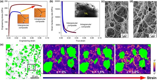
Strengthening and hardening via strong dislocation blockage and multiplication are critical for the high strength and ductility of metallic materials such as alloys [Citation32]. Metal composites with intragranular distribution of reinforcing particles are expected to obtain extraordinary mechanical properties via the similar mechanism. As indicated by the post-mortem transmission electron microscopy (TEM) images of deformed microstructure (Figure (b), inset), dislocation blockage and accumulation can be observed nearby the embedded TiB2 particles. This could lead to significant strain hardening of the SLM composite, as displayed in Figure (b). Specifically, we explain the underlying mechanisms of the remarkably improved ductility from the following two perspectives. First, fracture surface analyses show that the failure mechanism changes from interfacial debonding for the conventional PM composite (Figure (c)) to a typical ductile failure for the SLM composite (no crack nucleation at interfaces, Figure (d)). In our SLM composite, the intragranularly dispersed TiB2 reduces stress concentration at GBs, allowing large plastic deformation of Al matrix before crack nucleates. Second, KAM map identifies the presence of local misorientations nearby the intragranular particles, and the size of the local ‘domains’ increases with the applied strain (Figure (e)). Based on continuum elasticity theory, particles in the matrix are treated as Eshelby’s inclusion, where the elastic stress field increases with particle size [Citation33]. Thus, the intragranular TiB2 particle not only accumulates dislocations but also creates a relatively large elastic stress/strain field. This leads to the accumulation of geometrically necessary dislocations (GNDs) and the associated extra back-stress hardening. Also, the extensive GNDs distribution facilitates an interaction between GNDs and the gliding dislocations, which is promising for the extraordinary strain hardening in metallic materials [Citation34]. Therefore, the intragranular dispersion strategy in SLM composite has led the ability to combine two of the most important features for ductility improvements in metal composites, namely, the high strain hardening capacity and high fracture tolerance. On the contrary, for conventional metal composites where particles are distributed at GBs, the confinement of GNDs at GBs intensifies the local stress concentration, resulting in the early crack nucleation and material failure (Figure (c)). Furthermore, the localized GNDs at GBs reduce the interplay between dislocations, which in turn limits dislocation multiplication and accumulation. As a result, composite with the intergranularly distributed particles demonstrates limited strengthening efficiency, low strain hardening ability and low ductility (Figure (a,b)).
4. Conclusion
To conclude, we design and develop a new composite microstructure that enables remarkable strengthening and stress-delocalization. Our design strategy relies on the uniform dispersion of particles inside metal grains, which decouples stress concentrations induced by GBs and reinforcements. The resultant microstructure promotes dislocation multiplication and extra back-stress hardening, leading to enhanced tensile strength and ductility of the composites. The spontaneous engulfment of particles is achieved through rapid solidification, which is an intrinsic feature for laser-based additive manufacturing. Therefore, our approach could be transferred to other metal composite systems and a wide of additive manufacturing techniques.
Supplemental Material
Download MS Word (1.1 MB)Disclosure statement
No potential conflict of interest was reported by the author(s).
Additional information
Funding
References
- Mortensen A, Llorca J. Metal matrix composites. Annu Rev Mater Res. 2010;40:243–270.
- Chawla KK. Metal matrix composites. In: Composite materials. New York: Springer; 2012. p. 197–248.
- Rawal SP. Metal-matrix composites for space applications. JOM. 2001;53:14–17.
- Lin TC, Cao C, Sokoluk M, et al. Aluminum with dispersed nanoparticles by laser additive manufacturing. Nat Commun. 2019;10:4124.
- Chen LY, Xu JQ, Choi H, et al. Processing and properties of magnesium containing a dense uniform dispersion of nanoparticles. Nature. 2015;528:539–543.
- Ogawa F, Masuda C. Fabrication and the mechanical and physical properties of nanocarbon-reinforced light metal matrix composites: a review and future directions. Mater Sci Eng A. 2021;820:141542.
- Cao C, Yao G, Jiang L, et al. Bulk ultrafine grained/nanocrystalline metals via slow cooling. Sci Adv. 2019;5:eaaw2398.
- Lei T, Shin J, Gianola DS, et al. Bulk nanocrystalline Al alloys with hierarchical reinforcement structures via grain boundary segregation and complexion formation. Acta Mater. 2021;221:117394.
- Fu X, Tan Z, Min X, et al. Trimodal grain structure enables high-strength CNT/Al-Cu-Mg composites higher ductility by powder assembly & alloying. Mater Res Lett. 2021;9:50–57.
- Li Z, Guo Q, Li ZQ, et al. Regain strain-hardening in high-strength metals by nanofiller incorporation at grain boundaries. Nano Lett. 2018;15:8077–8083.
- Lei C, Du Y, Zhu M, et al. Microstructure and mechanical properties of in situ TiC/Ti composites with a laminated structure synthesized by spark plasma sintering. Mater Sci Eng A. 2021;812:141136.
- Zhang X, Xu Y, Wang M, et al. A powder-metallurgy-based strategy toward three-dimensional graphene-like network for reinforcing copper matrix composites. Nat Commun. 2020;11:2775.
- Li S, Wang X, Wei Z, et al. Simultaneously improving the strength and ductility of the as-sintered (TiB2 + La2O3)/Ti composites by in-situ planting ultra-fine networks into the composite powder. Scripta Mater. 2022;218:114835.
- Yan Q, Chen B, Cao L, et al. Improved mechanical properties in titanium matrix composites reinforced with quasi-continuously networked graphene nanosheets and in-situ formed carbides. J Mater Sci Technol. 2022;96:85–93.
- Youssef YM, Dashwood RJ, Lee PD. Effect of clustering on particle pushing and solidification behaviour in TiB2 reinforced aluminium PMMCs. Compos Part A. 2005;36:747–763.
- Wang G, Ouyang H, Fan C, et al. The origin of high-density dislocations in additively manufactured metals. Mater Res Lett. 2020;8:283–290.
- Martin JH, Yahata BD, Hundley JM, et al. 3D printing of high-strength aluminium alloys. Nature. 2017;549:365–369.
- Sen S, Juretzko F, Stefanescu DM, et al. In situ observations of interaction between particulate agglomerates and an advancing planar solid/liquid interface: microgravity experiments. J Cryst Growth. 1999;204:238–242.
- Kaptay G. Interfacial criterion of spontaneous and forced engulfment of reinforcing particles by an advancing solid/liquid interface. Metall Mater Trans A. 2001;32:993–1005.
- Kaptay G. Interfacial criteria to avoid pushing of particles during solidification of metal matrix composites. Mater Sci Forum. 2000;329–330:121–126.
- Stefanescu DM, Dhindaw BK, Kacar SA, et al. Behavior of particles at the solid-liquid metal interface in metal matrix composites. Metall Mater Trans A. 1988;19:2847–2855.
- Uhlmann DR, Chalmers B, Jackson KA. Interaction between particles and a solid-liquid interface. J Appl Phys. 1964;35:2986–2993.
- Chernov AA, Temkin DE, Mel’nikova AM. The influence of the thermal conductivity of a macroparticle on its capture by a crystal growing from a melt. Sov Phys Crystallogr. 1977;22:656–658.
- Shangguan D, Ahuja S, Stefanescu DM. An analytical model for the interaction between an insoluble particle and an advancing solid/liquid interface. Metall Trans A. 1992;23:669–680.
- Li Z, Cui Y, Yan W, et al. Enhanced strengthening and hardening via self-stabilized dislocation network in additively manufactured metals. Mater Today. 2021;50:79–88.
- Wang G, Zhang Y, Zou B, et al. Large volume dispersion of reinforcing particles in metal composites via controlled track scan in laser powder-bed-fusion. Under review.
- DebRoy T, Mukherjee T, Wei HL, et al. Metallurgy, mechanistic models and machine learning in metal printing. Nat Rev Mater. 2021;6:48–68.
- Ma Y, Addad A, Ji G, et al. Atomic-scale investigation of the interface precipitation in a TiB2 nanoparticles reinforced Al-Zn-Mg-Cu matrix composite. Acta Mater. 2020;185:287–299.
- Aboulkhair NT, Simonelli M, Parry L, et al. 3D printing of aluminium alloys: additive manufacturing of aluminium alloys using selective laser melting. Prog Mater Sci. 2019;106:100578.
- Kürnsteiner P, Wilms MB, Weisheit A, et al. High-strength Damascus steel by additive manufacturing. Nature. 2020;582:515–519.
- Schaffer PL, Miller DN, Dahle AK. Crystallography of engulfed and pushed TiB2 particles in aluminium. Scripta Mater. 2007;57:1129–1132.
- Meyers MA. Mechanical metallurgy principles and applications. New Jersey: Prentice-Hall; 1984.
- Ashby MF. The deformation of plastically non-homogeneous materials. Phil Mag. 1970;21:399–424.
- Zhao C, Zhou H, Lu Q, et al. Extra strengthening and work hardening in gradient nanotwinned metals. Science. 2018;362:eaau1925.