
Abstract
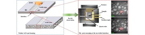
The pore fusion behavior of the core layer interface in the welded aluminum foam sandwich was observed through synchrotron radiation. Meanwhile, the effect of the FSW in foaming is explored. The FSW leads to the early formation of cracks in the core layer of powder in the weld zone. The heterogeneous nucleation of bubbles occurs at the interface and forms small pores. The evolutionary processes of small pores promote interfacial fusion. In addition, the presence of the panel changes the state of the melt at the interface, which benefits the fusion of the melt at the interface.
GRAPHICAL ABSTRACT
IMPACT STATEMENT
A new phenomenon was discovered and studied, where the interfacial fusion mechanism of the unwelded core layer facilitates the obtaining of welded aluminum foam sandwiches with homogeneous pores structure.
1. Introduction
Aluminum foam, a porous material inspired by nature, is produced by dispersing a gas phase in a metal matrix. It has attracted the curiosity of scholars with its unique properties in the last few years [Citation1]. The precursor foaming process is one of the industrialized manufacturing processes of aluminum foam, and the shaping of aluminum foam with high productivity is indispensable for its industrial production [Citation2–4]. In practical application, aluminum foams were produced by expanding multiple pieces of foamable precursor inside a mould to resolve the difficulty of making significant components [Citation5]. The evolutionary mechanism of metal melts with opacity, reactivity, high temperature, and low resistivity has been extensively explored [Citation6–12]. Meanwhile, the foaming mechanism of multiple precursors has received increased attention in recent years.
Nosko et al. [Citation13] reported that the initial position of the precursor in the mould would affect the heat conduction and pore formation kinetics during foaming, which affected the pore structure of the aluminum foam. Duarte et al. [Citation5] investigated the effect of precursor arrangement while taking into account their predominant growth direction and different thermal contacts between individual pieces of precursor. They discovered that placing precursors in such a way that the foam growth directions are perpendicular to each other results in better joining. However, aluminum foams produced using this method can create a non-uniform structure of pores. This phenomenon is equally influenced by mold characteristics, temperature processes, atmosphere, solidification details, multiple foaming, shape, surface/volume ratio, and precursor surface quality [Citation14–16].
An aluminum foam sandwich (AFS) is a material comprising an aluminum foam core and two metallic face plates. Presently, the friction stir welding method (FSW), which is originally developed for joining difficult-to-fusion weld Al-alloys to eliminate problems such as porosity formation [Citation17–22], is a well-applicated for joining AFS successfully to solve the size limitation problem in the current AFS panel preparation technology, such as powder metallurgy [Citation23]. The welded AFS by this method has an interface at the core layer, and the foaming process is similar to the aluminum foam prepared by expanding multiple pieces of foamable precursor inside a mould. The foaming mechanism may be significantly distinct, however, due to the different roles of the mold and the panels of AFS, as well as the influence of the FSW on the core layer powder. So far, there has been a lack of information on the interfacial evolution behavior of this AFS. In the present paper, the evolutionary behavior of the unwelded core interface of welded AFS during the foaming process, and the effect of the FSW technique on pore nucleation have been studied. In addition, the impact of the presence of AFS panels on the interfacial connection of the core layer is also explored.
2. Materials and methods
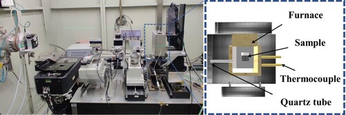
Synchrotron radiation has been widely applied in materials science [Citation24–26]. Compared to traditional microfocus X-rays, the synchrotron beams possessed a high intensity and very little dispersion, allowing for precise pictures of thin objects with exposure periods far below 1 s [Citation7]. Hence, the foaming process at the core interface of welded AFS was observed by this technology. Based on the 4W1A experimental station at the Beijing Synchrotron Radiation Facility (BSRF, Institute of High Energy Physics, Chinese Academy of Sciences, Beijing, China), the system for real-time, in situ, X-ray radioscopy during sample foaming was developed, as shown in Figure a. The synchrotron X-ray beam was monochromatized to 20 keV by a monochromator. It generated an absorption radiograph through the sample and analysis crystals captured with an electronic detector system based on a 1024×1024 pixel CCD camera with a 3.25 µm pixel size (VHR-16M High-resolution X-ray Imaging Camera system, Photonic Science Limited). An imaging field of view of 7.4 mm × 7.4 mm is convenient for observing the foaming process. The foaming was generated in a self-developed heating furnace with a rectangular hole (15 mm long and 15 mm wide) that the X-ray bean could pass. The exposure time range was adjusted from 300 ms to 1 s to obtain clear images according to the sample thickness. The Image J software (Version 1.49 National Institutes of Health, Bethesda, MD, USA) was used for adjusting contrast, brightness, background removal, and removing noise to maximize the characterization of pores from the images before collecting pore evolution data.
Figure 1. (a) the experimental setup consists of a synchrotron X-ray beam, a self-developed heating furnace, and a CCD camera. (b) a self-developed heating furnace, whose temperature is measured by two thermocouples, is used to control the foaming atmosphere and cooling rate by passing CO2 through quartz tubes into the furnace.
The AFS precursors were fabricated by the packing rolling powder metallurgy method. The friction stir welding was used for welding the precursor panels with the specific information described in [Citation23]. The samples to be used in synchrotron X-ray radioscopy experiments were taken in the weld zone with dimensions of 20 mm × 7 mm × 2 mm, and the surface of the cross-section was polished with 2000 grit paper to obtain clear images. The larger sample surfaces were always perpendicular to the welding direction. The rectangle specimens with the size of 240 mm × 120 mm were prepared to investigate the effect of AFS panels on the core layer foaming. The single side panel of the weld zone was peeled off using wire cutting and foamed at a preset furnace temperature of 625°C.
3. Results and discussion
The presence of panels improves the mechanical properties of AFS, such as yield compression, tension, torsion, or bending properties [Citation27,Citation28]. Moreover, it has a similar effect as the mould, affecting the foaming of the core layer powder. Figure shows the different interface conditions after the foaming of welded AFS precursors with different cavities. While the panel of the welded zone is stripped, the unwelded core layer is exposed directly to the air (left picture in the first row). The interface is separated to form two parts, and a denser oxide film is formed on the surface core layer after foaming see later two images in the first row. Conversely, the second-row images show that the melt near the edge of the panel is connected into a whole (image marked with red circles in the second row), the pores of the aluminum sandwich achieve a continuous structure, and no interface is present.
Figure 2. Schematic diagram of weld precursors with different panel treatments (left): the first row of weld precursor panels was stripped, which was not stripped in the second row. The physical diagram of AFS with different cavity conditions (middle) and schematic diagram of different core interfaces after foaming (right).
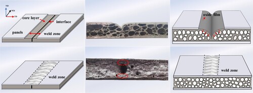
Undoubtedly, the interfacial fusion in the core layer of welded AFS has effects on various factors, among which the panels play an essential role. In the first case, the metal melt at the interface with weak wettability with gas tends to contract in the opposite direction (marked with the red arrow in Figure ) under surface tension to maintain the lowest energy state, which results in a large spacing between the unwelded linear interfaces of the core layers and form two separate curved interfaces. On the contrary, due to the wettability between the core melt and the panel being better than the gas, the melt spreads face-to-face on the panel and eventually fuses into a monolithic structure near the panel (middle picture in the second row). Briefly, the presence of the panel changes the force state between the melts and destroys the original tendency of the interface to shrink. As an "arch bridge," the panel promoted the integration of the two independent melts at the interface. Furthermore, the denser oxide film did not appear, which may be due to the presence of the panel preventing the oxidation of the core interface during the foaming.
FSW ensures a high-quality connection of the panel while having a specific impact on the foaming of the interface in the core layer. Figure demonstrates the early nucleation stage of welded AFS. An unwelded interface (1.5∼12.5 µm width) marked with a red arrow appears in the core layer, and the stirring action of the stirring needle mixes the core layer powder near the panel, causing the interface to vanish in the weld zone as shown in Figure a. There is a darker area in the welded zone in b (marked with a red rectangle). It starts to disappear at 148s, at which temperature is 573.6°C, and disappears completely after 9 s (in Figure c). The darker area (with stronger X-ray absorption than the matrix) [Citation29,Citation30] is the enriched area of cooper, which may be caused by the material flow in the weld zone during the FSW process [Citation31,Citation32]. Figure d shows the state of the powder in the weld zone marked with a red rectangle with a small gray value, which is significantly different from the matrix. During the foaming, it forms cracks before the matrix, which will form a large number of cracks after 13 s, as shown in Figure e, f. In the early stages, different gray values within the image correspond to the different states of the powder. The pores (white zones) are crack-like, oriented parallel to the transverse direction of the powder, and develop in a typical way from cracks to more spherical bubbles.
Figure 3. (a) Metallographic image of the interface in the core layer; Series images of the early stage of welded AFS monitored by x-ray radioscopy: (b)∼(c) the copper enriched area of the welded zone; (d)∼(f) the formation process of cracks in the welded zone and the matrix.
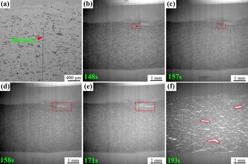
It was found that pore formation occurs at the weak points in the matrix (e.g. low-melting components) [Citation1,Citation32,Citation33]. One reason for the early occurrence of the cracks at the weld zone is the alloy composition of AlSi6Mg4Cu4, which results in copper-enriched in the weld zone during the FSW, as shown in Figure b. Furthermore, the addition of Cu to the Al–Si–Mg alloys can reduce the melting temperature [Citation34], the solidus and liquidus temperatures of the quaternary alloy AlSi6Mg4Cu4 were calculated to be 507 and 596 °C [Citation35], respectively. The dissolution of Cu occurs at low temperatures, leading to type II nucleation [Citation32], which may prematurely produce cracks in the weld zone. In addition, the previous study found that one factor influencing the production of commercial aluminum foam with excellent foam structure and foaming properties by powder metallurgy is good powder compressibility with a relative density of more than 98% [Citation36]. In preparing the AFS precursor using the packing rolling powder metallurgy method, there is still microporosity in the dense core layer powder matrix. During the friction stir welding process, the intense plastic deformation reduces the microporosity in the powder of the welded zone and becomes dense. The high density of the core layer powder provides further conditions for the formation of cracks.
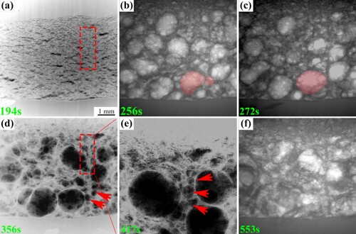
FSW technology not only affects the foaming of the core layer, but more considerably, the AFS welded by this method after foaming, the unwelded core layer can also be on to obtain a continuous bubble hole structure. In this process, the process of pore evolution is a worthwhile in-depth study. Figure shows the dynamic in-situ observation process of the pores at the core layer interface. When the precursor heats for 272s, the rapid expansion of the precursor occurs. In this stage, cracks are formed at the core layer interface location in 194s, as shown in Figure a. In particular, the pores at the interface coalesce in this stage with increased sphericity. As an example, when two pores come into contact, a completely elastic bubble surface would shrink at an increasing rate as pressure scales with the inverse of bubble diameter according to Laplace's law [Citation10], so that the large bubble engulfs and merges the small bubble to form a larger one shown in Figure c. The small-sized pores with an average diameter of 0.38 mm formed at the interface in Figure d. The phenomenon of a high-density region, see the red region in Figure d, that may cause by the outer oxide layer in the local area is observed at the interface which will result in the pore structure uneven. However, the pores with smaller sizes (0.49 mm), as seen in Figure e, will be formed in this area, causing the high-density region to vanish. In addition, the small interfacial distance of the core layer after FSW helps to reduce the generation of oxide layers. Moreover, magnesium also contributes to the oxide layer's dissolution, reducing the oxide layer's role and making the high-density region disappear [Citation37–39]. In summary, forming small pores at the interface leads to the disappearance of highly dense regions. In addition, small pores are unstable and prone to merge with large pores, making the interface disappear. Small pores’ nucleation, growth, and coalescence at the interface promote interfacial fusion.
Figure 4. Series of images of interface monitored by x-ray radioscopy: (a) cracks at the interface; (b)∼(c). pore coalescence marked with red; (d) small pores and the high-density region at the interface marked with arrows and rectangular; (e) small pores in the high-density region marked by arrows; (f) foam collapse. Figs (a), (d), and (e) were LUT processed for better observation of small pores.
4. Conclusion
Welded AFS with an interface in the core layer was studied for the interface fusion mechanism. Studies revealed that the panels change the force state of the melt in the interface, promoting interfacial fusion during the foaming. Synchrotron radiation technology enables in-situ observation of the interface foaming process. FSW technology would cause the powder in the welded zone to form cracks in advance. The nucleation and growth of small pores at the unwelded interface make the high-density region disappear, and the coalescence between the bubbles facilitates the fusion of the interface.
Disclosure statement
No potential conflict of interest was reported by the author(s).
Additional information
Funding
References
- Kamm PH, Neu TR, Garcia-Moreno F, et al. Nucleation and growth of gas bubbles in AlSi8Mg4 foam investigated by Xray tomoscopy. Act. Mater. 2021. DOI:10.1016/j.actamat.2020.116583
- Hangai Y, Kawato D, Ando M, et al. Nondestructive observation of pores during press forming of aluminum foam by Xray radiography. Mater. Charact. 2020. DOI:10.1016/j.matchar.2020.110631
- Baumgartner F, Duarte I, Banhart J. Industrialization of powder compact toaming proces. Adv. Eng. Mater. 2000;2:168–174.
- Banhart J. Light-Metal foams-history of innovation and technological challenges. Adv. Eng. Mater. 2013;15:82–111.
- Duarte I, Oliveira M, Garcia-Moreno F, et al. Foaming of AA 6061 using multiple pieces of foamable precursor. Colloid. Surface. A. 2013;438(45):47–55.
- Helfen L, Baumbach T, Stanzick H, et al. Viewing the early stage of metal foam formation by computed tomography using synchrotron radiation. Adv. Eng. Mater. 2002;4:808–813.
- Banhart J, Stanzick H, Helfen L, et al. Metal foam evolution studied by synchrotron radioscopy. Appl. Phys. Lett. 2001;78:1152–1154.
- Garcia-Moreno F, Mukherjee M, Jiménez C, et al. Metal foaming investigated by X-ray radioscopy. Metals (Basel). 2012;2:10–21.
- Villanova J, Daudin R, Lhuissier P, et al. Fast in situ 3D nanoimaging: a new tool for dynamic characterization in materials science. Mater Today. 2017;20:354–359.
- García-Moreno F, Kamm PH, Neu TR, et al. Using X-ray tomoscopy to explore the dynamics of foaming metal. Nat. Commun. 2019. DOI:10.1038/s41467-019-11521-1
- García-Moreno F, Kamm PH, Neu TR, et al. Tomoscopy: time-resolved tomography for dynamic processes in materials. Adv. Mater. 2021. DOI:10.1002/adma.202104659
- García-Moreno F, Banhart J. Influence of Gas pressure and blowing agent content on the formation of aluminum alloy foam. Adv. Eng. Mater. 2021;23:242–250.
- Nosko M, Simančík F, Florek R. Reproducibility of aluminum foam properties: effect of precursor distribution on the structural anisotropy and the collapse stress and its dispersion. Mater Sci Eng A. 2010;527:5900–5908.
- Duarte I, Oliveira M. Aluminium alloy foams: production and properties. In: K Kondoh, editor. Powder metallurgy. Croatia: InTech, Rijeka; 2012. p. 47–72.
- Duarte I, Banhart J. A study of aluminium foam formation-kinetics and microstructure. Act. Mater. 2000;48:2349–2362.
- Baumeister J, Stöbener K. Investigations on expansion behavior of granulated foamable precursor material. In: Banhart J, Fleck, NA, Mortensen, A, editor, Cellular metals: manufacture, properties, applications. Berlin: Metall Innovation Technologie MIT-Verlag; 2003. p. 143–146.
- Çam G, Javaheri V, Heidarzadeh A. Advances in FSW and FSSW of dissimilar Al-alloy plates. J. Adhes. Sci. Technol. 2022. DOI:10.1080/01694243.2022.2028073
- Kashaev N, Ventzke V, Çam G. Prospects of laser beam welding and friction stir welding processes for aluminum airframe structural applications. J. Manuf. Process. 2018;36:571–600.
- Çam G, Ipekoglu G. Recent developments in joining of aluminium alloys. Int. J. Adv. Manuf. Technol. 2017;91:1851–1866.
- Cam G. Prospects of producing aluminum parts by wire arc additive manufacturing (WAAM). Mater Today Proc. 2022;62 (1):77–85.
- Ipekoglu G, Çam G. Formation of weld defects in cold metal transfer arc welded 7075-T6 plates and its effect on joint performance. IOP conf. series: materials science and engineering; 2019; 629: 012007.
- Cam G, Ventzke V, Dos Santos JF, et al. Characterisation of electron beam welded aluminium alloys. Sci. Technol. Weld. Join. 1999;4(5):317–323.
- Su XX, Huang P, Feng ZH, et al. Study on aluminum foam sandwich welding by friction stir welding technology. Mater. Lett. 2021. DOI:10.1016/j.matlet.2021.130605
- Yang CX, Wu SJ, Wu SC, et al. In-situ characterization on crack propagation behavior of SiCf/SiC composites during monotonic tensile loading. J.Eur.Ceram.Soc. 2022;42:6836–6845.
- Wu SC, Song Z, Kang GZ, et al. The kitagawa-takahashi fatigue diagram to hybrid welded AA7050 joints via synchrotron X-ray tomography. Int J Fatigue. 2019;125:210–221.
- Wu SC, Xiao TQ, Withers PJ. The imaging of failure in structural materials by synchrotron radiation X-ray microtomography. Eng.Fract.Mech. 2017;182:127–156.
- Banhart J, Seeliger HW. Aluminium foam sandwich panels: manufacture, metallurgy and applications. Adv. Eng. Mater. 2008;10:793–802.
- Neu TR, Kamm PH, Eltz N, et al. Correlation between foam structure and mechanical performance of aluminium foam sandwich panels. Mater Sci Eng A. 2021. DOI:10.1016/j.msea.2020.140260
- Sun X, Huang P, Zhang X, et al. Densification mechanism for the precursor of AFS under different rolling temperatures. Mater. 2019;12:1–11.
- Zhu PP, Yuan QX, Huang WX, et al. Principles of X-ray diffraction enhanced imaging. Acta. Phys. Sin-Ch. Ed. 2006;55:1089–1097.
- Jiménez C, Paeplow M, Kamm PH, et al. Simultaneous X-ray radioscopy/tomography and energy-dispersive diffraction applied to liquid aluminium alloy foams. J. Synchrotron. Radiat. 2018;25:1790–1796.
- Rack A, Helwig HM, Bütow A, et al. Early pore formation in aluminium foams studied by synchrotron-based microtomography and 3-D image analysis. Act. Mate. 2009;57:4809–4821.
- Yang CC, Nakae H. The effects of viscosity and cooling conditions on the foamability of aluminum alloy. J. Mater. Process. Technol. 2003;141:202–206.
- Ding X, Peng B, Hu SX, et al. Effect of Cu and Sn additions on the cellular structure of Al-Si-Mg alloys foaming at low temperature (≤600 °C). Compos. Part. B-Eng. 2022. DOI:10.1016/j.compositesb.2022.109693
- Helwig HM, Garcia-Moreno F, Banhart J. A study of Mg and Cu additions on the foaming behaviour of Al-Si alloys. J. Mater. Sci. 2011;46:5227–5236.
- Helwig HM, Hiller S, Garcia-Moreno F. Influence of compaction conditions on the foamability of AlSi8Mg4 alloy. Metall Mater Trans B. 2009;40:755–767.
- García-Moreno F, Radtke LA, Neu TR. The influence of alloy composition and liquid phase on foaming of Al-Si-Mg alloys. Metals (Basel). 2020. DOI:10.3390/met10020189
- Lumley R, Sercombe T, Schaffer G. Surface oxide and the role of magnesium during the sintering of aluminum. Metall Mater Trans A. 1999;30:457–463.
- Nagelberg AS, Antolin S, Urquhart AW. Formation of Al2O3/metal composites by the directed oxidation of molten aluminum-magnesium-silicon alloys: part II. Growth Kinetics J. Am. Ceram. Soc. 1992;75:455–462.