
 ?Mathematical formulae have been encoded as MathML and are displayed in this HTML version using MathJax in order to improve their display. Uncheck the box to turn MathJax off. This feature requires Javascript. Click on a formula to zoom.
Abstract
Cycling-induced cathode interfacial degradations are usually attributed to chemical process, while the physical effect is overlooked to a large extent. Herein, we investigate the failure mechanism of LiCoO2 cathode and reveal that misfit strain plays a dominant role in the surface layer exfoliation process. We illustrate that highly strained LiCoO2 surface can initiate massive surface cracks, leading to the LiCoO2 surface layer broken and exfoliation. Mechanical cracking coupled with chemical etching aggravates the surface layer degradation, leading to a weathering-like degradation on LiCoO2 surface. Our work reveals that interfacial degradation of electrode materials is a complex physicochemical process.
Impact Statement
Interfacial degradations are usually believed as chemical effect dominated failure. Herein, we show that the overlooked physical effect, misfit strain, in fact plays a critical role in the surface degradation process and stress that LiCoO2 surface degradation is a complex physicochemical process.
GRAPHICAL ABSTRACT

1. Introduction
Solid/liquid interfaces in a rechargeable battery govern the charge transfer kinetics thus playing key roles in determining battery performance [Citation1–4]. Chemical instability-induced interfacial degradations at the cathode side is particularly important, which mainly include cathode/electrolyte interphase (CEI) formation [Citation5,Citation6], surface layer phase transformation [Citation7–9], reduction and dissolution of transition metal ions [Citation10,Citation11] and oxygen loss [Citation12–14]. CEI passivation layer and surface phase transformation layer (SPTL) are acting as blocking layers for charge transfer, causing voltage fading, capacity decay and poor rate capability [Citation5,Citation7]. Cathode surface erosion and fragmentation is a typical interfacial degradation, which causes the dissolution of transition metal (TM) ions into electrolytes [Citation15,Citation16]. TM migration and dissolution can accelerate irreversible structural transformation of cathode and passivate active surface, blocking lithium–ion intercalation and deintercalation [Citation11,Citation17]. TM loss also can induce surface pits, voids and cracks, which have been frequently observed at the layered cathode surface after electrochemical cycling [Citation18,Citation19]. These defects expose inner bulk to electrolyte, causing new sites for interfacial degradation [Citation20]. Continuously interfacial side reactions not only consume electrolyte but also cause gradual capacity decay due to the loss of active cathode materials [Citation15]. Moreover, the dissolved TM cations not only catalyze the decomposition of the electrolyte but also migrate and deposit on electrode surface causing SEI layer instability [Citation17,Citation21]. Fully understanding the cathode interfacial degradation is vital for realizing high cycling performance.
The chemical effect on cathode surface degradation has been widely recognized, such as surface etching, surface side reactions, especially the attack of acid HF species [Citation16,Citation22,Citation23]. Electrochemical cycling of layered structure can also lead to mechanical degradations, which is mainly due to delithiation-induced lattice deformation and phase transition [Citation24–27]. Such a physical effect incurs increasing attention recently and has been investigated intensively [Citation28]. As for the surface degradation layer, the lattice misfit strain between the surface phase transition layer (SPTL) and the matrix can cause an innegligible issue, which has not been studied systematically. In this work, we take commercial LiCoO2 cathode as an example to reveal the interfacial degradations and its evolution process upon prolonged cycles. Through microscopic characterizations and theoretical simulations, we show that LiCoO2 particles undergo a weathering-like surface degradation, in which misfit strain-induced mechanical cracking plays a key role in facilitating the SPTL exfoliation process. Our work highlights that mechanical failure plays an important role in the interfacial degradation process for those electrode materials suffering high interfacial strain.
2. Experimental section
2.1. Electrochemical performance tests
LiCoO2 cathode materials were purchased from Shenzhen Kejing Star Technology Co. Ltd. The electrochemical performance was tested with 2032 coin-type cells. First, the cathode electrodes, carbon black and polyvinylidene difluoride (PDVF) are mixed at a weight ratio of 8:1:1 in NMP stirred for 6 h. Then, slurry was cast onto carbon-coated Al foil current collector.
The carbon-coated Al foil with slurry is dried in a vacuum oven for 12 h at 60°C. All coin cells are assembled in an argon-filled glovebox with a metallic lithium foil as the counter electrodes, a Celgard 3501 polypropylene membrane as a separator, and the 1 M LiPF6 in ethylene carbonate and ethyl methyl carbonate (3:7 EC:EMC weight ratio) as the electrolyte. All cells are cycled at 0.2C rate (1C = 140 mA/g) with different voltage windows, 2.7–4.4 V, 2.7–4.55 V and 2.7–4.7 V.
2.2. Characterization methods
SEM imaging and TEM specimen preparation were conducted on an FEI Helios DualBeam Focused Ion Beam operating at 2–30 kV. First, a 1-μm-thick Pt layer was deposited on a region to avoid Ga ion beam damage in the subsequent lift-out and thinning process. After lift out, the specimen was thinned to 200 nm using 30 kV Ga ion beam by reducing the current gradually. Then the surface was polished by a 5-kV Ga ion beam to remove the surface damage layer and further thinning to electron transparency. Finally, a 2-kV Ga ion beam was used to clear the surface damage layer. Specimens were characterized using a probe spherical aberration transmission electron microscope (FEI Titan G2 60-300) with an acceleration voltage of 300 kV. In-situ X-ray diffraction (XRD) tests were carried out using a Bruker D8 Advance X-ray diffractometer.
3. Results and discussion
3.1. Interfacial degradations dominating LiCoO2 decay at 4.2 V
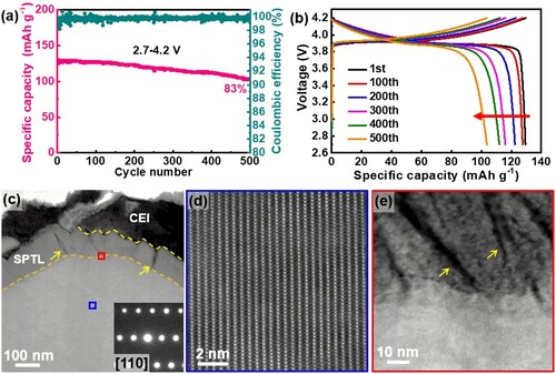
When cycled at voltage window 2.7–4.2 V, LiCoO2 performance decay is mainly due to the incremental capacity loss, while the voltage fading is negligible. As shown in Figure (a), the capacity retention is 83% after 500 cycles. Figure (b) shows the voltage fading is negligible. To understand the origins of LiCoO2 capacity decay, the cycled electrode is characterized by electron microscopy and XRD. Our results indicate that grain bulk does not show any appreciable changes even after 500 cycles at 2.7–4.2 V (Figure c, d and Figure S1). As revealed by the selected area electron diffraction (SAED) pattern (Figure c) and high angle annular dark field (HAADF) lattice image (Figure d), layered structure is well preserved. In contrast, we observed severe interfacial degradations at LiCoO2 surface. As shown in Figure (c), the surface phase transformation layer (SPTL) is as thick as 110 nm, and massive cracks are generated in the surface layer as denoted by the yellow arrows. More tiny cracks can be seen from the high magnification TEM image in the SPTL as shown in Figure (e), indicating the cracks are originated at the LCO/SPTL interface. The lattice structure of SPTL is a spinel-like structure (Figure S2) and many etching dots are formed (Figure e) due to massive Co dissolution and O loss as evidenced by EDS mapping (Figure S3). Our characterizations indicate that interfacial degradations are the major cause of the performance decay for the LiCoO2 cathode cycled at 2.7–4.2 V. Similar results were obtained from the sample after 300 cycles at 2.7–4.2 V (Figure S4).
Figure 1. Electrochemical performance and microstructure characterizations. The LCO/Li-metal half-cell is cycled at 0.2 C rate (1C = 140 mA g−1) in the voltage window 2.7–4.2 V. (a) Capacity retention and corresponding columbic efficiencies. (b) The corresponding charge/discharge voltage profiles, showing only capacity decay is significant (highlighted by the red arrow). (c) STEM-HAADF image to show a LiCoO2 particle after 500 cycles. Many cracks are formed in the SPTL highlighted by yellow arrows. Inset diffraction pattern is from the grain bulk, showing the well-preserved layered structure. (d) The lattice image from the blue area in (c), reveals the well-defined layered structure in the bulk. (e) Enlarged image from the red area in (c) to show the defective SPTL with high density of cracks and voids (dark contrast).
3.2. Mechanical cracking induced surface layer exfoliation
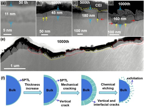
The SPTL thickness increases with increasing the cycle numbers. As shown in Figure (a–c), under 2.7–4.2 V operation, the typical SPTL thickness is about 11 nm after 50 cycles, 45 nm after 100 cycles and 180 nm after 500 cycles. With the increase of the SPTL thickness, surface cracks are gradually developed. The crack density increases with increasing cycle numbers as shown in Figure (b–d). The cracks are first initiated from the SPTL (Figure b), which are vertical to the SPTL/matrix interfaces, and with the thickness increase of the SPTL, the cracks deflect to the SPTL/matrix interfaces as indicated by red arrows in Figure (c, d) and Figure S5. The vertical cracks and the interfacial cracks are indicated by yellow arrows and red arrows, respectively. As shown in Figure (e), further extending the interfacial cracks along the interface finally leads to the SPTL exfoliation. Surface SPTL exfoliation is not homogeneous, which leads to a bumpy surface morphology and the SPTL thickness varies accordingly. More examples are shown in Figure S6. Figure (f) illustrates the whole evolution process of the LCO surface during cycling. First, a uniform SPTL layer is formed at the LCO surface and then vertical cracks are developed in the SPTL. Further increasing the SPTL thickness leads to interfacial cracks along the SPTL/matrix interfaces, which causes the exfoliation of the SPTL. Electrolyte penetration into the freshly formed cracks leads to a chemical etching effect, which can significantly accelerate the exfoliation of the SPTL.
Figure 2. Surface cracking and exfoliation process. (a–c) STEM-HAADF images show the SPTL thickness after different cycle numbers. The vertical cracks (yellow arrows) are formed in (b) after 100 cycles. The interfacial cracks (red arrows) are formed after more cycles in (c, d). (d, e) STEM-HAADF images of LiCoO2 particle after 1000 cycles, showing the SPTL are exfoliated. The SPTL shows gray contrast on the LCO surface. Completely exfoliated SPTL is highlighted by the dashed yellow lines. (f) Schematic diagrams to illustrate the surface layer exfoliation process during the cycling of LiCoO2.
3.3. Misfit strain-induced cracking.
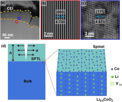
When the LiCoO2 surface undergoes degradation, its original layered structure transforms into the spinel-like structure. As shown in the STEM-HAADF images (Figure a–c), the SPTL is epitaxially grown on the LiCoO2 substrate after 300 cycles, in which the SPTL (111) plane is parallel to the layered (003) planes. As shown in Figure (b), the plane spacing of layered (003) is 4.73 Å, while the SPTL (111) plane spacing is 4.67 Å. Although the lattice mismatch is small (∼1.3%) between the SPTL and the LiCoO2 substrate, misfit strain still accumulates upon the SPTL growth. Figure (d) illustrates that when the SPTL exceeds a critical thickness (h), crack will be initiated to release the misfit strain energy. Crack relaxes strain energy but gives rise to new surface energy. Only when the relaxed strain energy is greater than the surface energy, cracking becomes energetically favorable [Citation29]. According to the film-substrate system, the critical thickness (hc) for crack formation is given by
(1)
(1) where Γ is the fracture resistance which is equal to the SPTL (111) plane surface energy, ESPTL is the Young’s modulus, ν is the Possion’s ratio, Z is a dimensionless driving force, depending on the cracking pattern and elastic mismatch. Generally, thin film cracking models could be classified into five different types: surface crack, channeling, substrate damage, spalling and debonding [Citation30]. In our case, the cathode particle exhibits channeling cracks without bulk damage, as shown in Figure (d). Therefore, Z = 1.976 [Citation30]. σ is the stress experienced by lattice mismatch at the SPTL/bulk interface, which is characterized as uniaxial tensile stress [Citation31]
(2)
(2)
Figure 3. Misfit-strain induced surface crack. (a–c) STEM-HAADF images of a LiCoO2 particle after 300 cycles. High-resolution lattice images from (b) the LCO substrate and (c) the SPTL, where the plane spacing of layered (003) is 4.73 Å and that of spinel SPTL (111) planes is 4.67 Å. (d) A film-substrate model to show the crack generation in the SPTL under tensile stress. Enlarged interfacial lattice structure model shows the misfit strain between delithiated LCO and SPTL.
where dbulk is the (003) plane spacing and dSPTL is the SPTL (111) plane spacing.
The calculation parameters are listed in Table S1 [Citation32,Citation33]. Due to lithiation/delithiation induced lattice breathing, the (003) plane can reach 4.81 Å at 50% delithiation (Li0.5CoO2), which is evidenced by our in-situ XRD test (Figure S7) and previous result [Citation34]. Thus the critical thickness hc is estimated as 13 nm, which is consistent with our experimental observations that cracks are usually generated in the SPTL thicker than 20 nm (Figure and Figure S8).
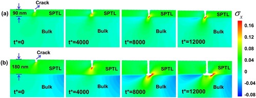
To further investigate the crack propagation for the SPTL beyond the critical thickness, an electro-chemo-mechanical phase field model is developed. The anisotropic lithium diffusion, the heterogeneous structure containing an SPTL and LCO matrix, and electrolyte penetration into the propagating surface crack are considered in this model. The detail description is shown in Figure S9. Since the SPTL thickness affects crack formation and crack propagation (Figure ), 90 nm SPTL (thin model) and 180 nm SPTL (thick model) are considered for the simulation. The crack propagation and stress evolution are shown in Figure S10 and Figure (the enlarged images of the crack region in Figure S10). Misfit strain and lithium gradient-induced strain are considered as shown in Figure S11 and the stress caused by the SPTL and the lithium gradient are shown in Figure S12 and Figure S13, respectively, which demonstrates that the stress magnitude is mainly determined by the SPTL due to the large lattice mismatch. The simulation results show that the crack grows vertically to the bulk/SPTL interface and stops at the interface for the thin SPTL model (Figure a). While for the thick SPTL model, when the surface vertical crack reaches the SPTL/bulk interface, it deflects to the interface (Figure b). The reason why the crack can deflect to the SPTL/bulk interface rather than penetrating the LCO matrix is attributed to two main reasons. One is that the stress magnitude caused by the thick SPTL is large enough to trigger the interface crack. The other is that the fracture resistance of LCO is higher than that of the SPTL, which prevents the crack to penetrate the LCO substrate. Our experimental observations also validate that the LCO underneath the SPTL is defect free (as shown in Figure S14). Note that deflection cracks into the SPTL/bulk interface causes the SPTL exfoliation from particle surface, which is detrimental.
Figure 4. Simulation of the crack propagation. The evolutions of dimensionless hydrostatic stress and the set surface crack at different dimensionless times t* = 0, t* = 4000, t* = 8000 and t* = 12000. (a) Thin SPTL model. When the SPTL thickness as 90 nm, the crack propagates vertically to the bulk/SPTL interface. (b) Thick SPTL model. The crack grows vertically and then bent to interfacial at the bulk/SPTL interface.
It is worth mentioning that the interfacial strain can also originate from the CEI layer. As shown in the TEM images, a thick CEI layer is usually found on the top of the SPTL. Based on the previous investigations, Young’s modulus of SEI is usually below 5 GPa [Citation35–39], which is much lower than that of the LCO substrate (191 GPa) [Citation40]. Therefore, in our case the CEI-induced strain is negligible. However, if the cathode particle is a secondary particle with the presence of cycling-induced massive cracks, the CEI-induced strain is not negligible anymore [Citation41,Citation42]. Additionally, based on our TEM observations, cracks can nucleate both from the LCO/SPTL interface and the SPTL/CEI interface (as shown in Figure S15), indicating the intricate chemo-mechanical coupling effect in facilitating the crack nucleation.
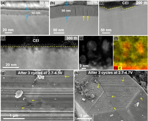
High voltage LiCoO2 is attracting increasing attention due to its high energy density. Our observations show that increasing the charge cutoff voltage leads to severe surface degradations. As shown in Figure (a–f) and Figure S16, the LCO sample is cycled at 2.7–4.4 V, SPTL exfoliation occurs significantly faster. The faster interfacial degradation leads to faster performance decay. The capacity retention is 59% after 300 cycles at 2.7–4.4 V cycling (Figure S17). The SPTL is observed again with extended cycling (e.g. the sample after 700 cycles) as shown in Figure S18, indicating that the SPTL undergoes formation–exfoliation–reformation process upon continuous cycling. Massive small fragmented pieces are found in the CEI layer as shown in Figure (d–f) and Figure S19. Increasing the cutoff voltage to 4.5 and 4.7 V, LCO surface cracks can be observed only after two cycles as shown in Figure (g, h).
Figure 5. Evolution of the SPTL when cycled at 2.7–4.4 V. (a–d) STEM-HAADF images to show the thickness of the SPTL when cycled at 2.7–4.4 V at different cycle numbers. The SPTL exfoliation is observed in (c, d). (e, f) EDS-mapping images show the fragmented pieces near the surface of bulk including Co elements and strong C signal, indicating that the SPTL fragments are entrapped in the CEI layer. (g–h) SEM images to show the massive cracks formed on the surface of LiCoO2 particle cycled at higher voltages, 4.5 and 4.7 V respectively.
Cycling-induced surface structure reconstruction is a very common behavior for many battery materials, including other layered cathodes, spinel-structure cathodes, olivine-structure polyanion cathodes and other electrode materials for rechargeable batteries [Citation43–47]. As long as the surface reconstruction layer is developed, the misfit strain builds up. Mechanically, the strain can generate cracks to cause particle fragmentations. Chemically, strain can assist chemical etching and corrosion to speed up the surface degradation process. The degradation is a complexed physicochemical process, which mimics the rock weathering process as illustrated in Figure S20 [Citation48]. Such a crack–corrosion–exfoliation process is more than a pure chemical etching effect. Therefore, to effectively stabilize the interface/surface of battery materials, it is essential to consider both physical and chemical effects together.
4. Conclusion
Through intensive microscopy analysis of the surface degradation process of LiCoO2, we reveal that the misfit-strain induced cracking plays a critical role in the surface degradation process. Such physical effect initiates cracks and fresh surfaces, which exaggerates the chemical effects, like side reactions, etching and corrosion. Combining the physical and chemical effects, the LiCoO2 surface suffers a weathering-like surface degradation process, featuring with surface layer exfoliation and corrosion. Surface degradation-induced surface structure reconstruction is a common phenomenon for various battery materials. Our work stresses that physical strain effect can be a dominant factor for surface layer degradation, which further deepens our understanding of the interfacial degradation mechanisms of battery materials and provides valuable insights for stabilizing interface/surface.
Supplemental Material
Download MS Word (8.5 MB)Disclosure statement
No potential conflict of interest was reported by the author(s).
Additional information
Funding
References
- Yu X, Manthiram A. Electrode–electrolyte interfaces in lithium-based batteries. Energ Environ Sci. 2018;11:527–543.
- Ramanujapuram A, Gordon D, Magasinski A, et al. Degradation and stabilization of lithium cobalt oxide in aqueous electrolytes. Energ Environ Sci. 2016;9:1841–1848.
- Xu K. Electrolytes and interphases in Li-ion batteries and beyond. Chem Rev. 2014;114:11503–11618.
- Armand M, Endres F, MacFarlane DR, et al. Ionic-liquid materials for the electrochemical challenges of the future. Nat Mater. 2009;8:621–629.
- Zhang JN, Li Q, Wang Y, et al. Dynamic evolution of cathode electrolyte interphase (CEI) on high voltage LiCoO2 cathode and its interaction with Li anode. Energy Storage Mater. 2018;14:1–7.
- Lu W, Zhang J, Xu J, et al. In situ visualized cathode electrolyte interphase on LiCoO2 in high voltage cycling. ACS Appl Mater Inter. 2017;9:19313–19318.
- Tornheim A, Sharifi-Asl S, Garcia JC, et al. Effect of electrolyte composition on rock salt surface degradation in NMC cathodes during high-voltage potentiostatic holds. Nano Energy. 2019;55:216–225.
- Wen Y, Xiao D, Liu X, et al. Microstructure dynamics of rechargeable battery materials studied by advanced transmission electron microscopy. NPG Asia Mater. 2017;9:e360–e360.
- Boulineau A, Simonin L, Colin JF, et al. First evidence of manganese-nickel segregation and densification upon cycling in Li-rich layered oxides for lithium batteries. Nano Lett. 2013;13:3857–3863.
- Kikkawa J, Terada S, Gunji A, et al. Chemical states of overcharged LiCoO2 particle surfaces and interiors observed using electron energy-loss spectroscopy. J Phys Chem C. 2015;119:15823–15830.
- Ko DS, Park JH, Park S, et al. Microstructural visualization of compositional changes induced by transition metal dissolution in Ni-rich layered cathode materials by high-resolution particle analysis. Nano Energy. 2019;56:34–442.
- Sharifi-Asl S, Soto FA, Nie A, et al. Facet-dependent thermal instability in LiCoO2. Nano Lett. 2017;17:2165–2171.
- Gao X, Ikuhara YH, Fisher CAJ, et al. Oxygen loss and surface degradation during electrochemical cycling of lithium-ion battery cathode material LiMn2O4. J Mater Chem A. 2019;7:8845–8854.
- Yan P, Zheng J, Tang ZK, et al. Injection of oxygen vacancies in the bulk lattice of layered cathodes. Nat Nanotechnol. 2019;14:602–608.
- Zheng J, Gu M, Xiao J, et al. Corrosion/fragmentation of layered composite cathode and related capacity/voltage fading during cycling process. Nano Lett. 2013;13:3824–3830.
- Zhan C, Wu T, Lu J, et al. Dissolution, migration, and deposition of transition metal ions in Li-ion batteries exemplified by Mn-based cathodes – a critical review. Energ Environ Sci. 2018;11:243–257.
- Zhan C, Lu J, Jeremy Kropf A, et al. Mn(II) deposition on anodes and its effects on capacity fade in spinel lithium manganate-carbon systems. Nat Commun. 2013;4:2437.
- Ryu HH, Park KJ, Yoon CS, et al. Capacity fading of Ni-rich Li[NixCoyMn1–x–y]O2 (0.6 ≤ x ≤ 0.95) cathodes for high-energy-density lithium-Ion batteries: bulk or surface degradation? Chem Mater. 2018;30:1155–1163.
- Yan P, Zheng J, Xiao J, et al. Recent advances on the understanding of structural and composition evolution of LMR cathodes for Li-ion batteries. Front Energy Res. 2015;3.
- Ryu HH, Park GT, Yoon CS, et al. Microstructural degradation of Ni-rich Li[NixCoyMn1-x-y]O2 cathodes during accelerated calendar aging. Small. 2018;14:e1803179.
- Xiao B, Sun X. Surface and subsurface reactions of lithium transition metal oxide cathode materials: An overview of the fundamental origins and remedying approaches. Adv Energy Mater. 2018;8:1802057.
- Liu T, Dai A, Lu J, et al. Correlation between manganese dissolution and dynamic phase stability in spinel-based lithium-ion battery. Nat Commun. 2019;10:4721.
- Aurbach D, Markovsky B, Salitra G, et al. Review on electrode–electrolyte solution interactions, related to cathode materials for Li-ion batteries. J Power Sources. 2007;165:491–499.
- Li Y, Li X, Du C, et al. Degradation by kinking in layered cathode materials. ACS Energy Lett. 2021;6:3960–3969.
- Oh J, Lee S, Kim H, et al. Overcharge-Induced phase heterogeneity and resultant twin-like layer deformation in lithium cobalt oxide cathode for lithium-Ion batteries. Adv Sci. 2022;14:2203639.
- Yan P, Zheng J, Gu M, et al. Intragranular cracking as a critical barrier for high-voltage usage of layer-structured cathode for lithium-ion batteries. Nat Commun. 2017;8:14101.
- Vemulapally A, Jangid M, Bhandakkar T, et al. Transformation induced plasticity drives stress instability during electrochemical delithiation of LiCoO2. J Electrochem Soc. 2021;168:060551.
- Stallard J, Wheatcroft L, Booth S, et al. Mechanical properties of cathode materials for lithium-ion batteries. Joule. 2022;6:984–1007.
- Krabbe M. Crack mechanisms and crack interaction in thin fims. Tech Rep Mech Engin. 2012;1:34.
- Hutchinson JW, Suo Z. Mixed mode cracking in layered materials. Adv Appl Mech. 1991;29:63–191.
- Jothilingam R, Koch MW, Posthill JB, et al. A study of cracking in GaN grown on silicon by molecular beam epitaxy. J Electron Mater. 2001;30:281–284.
- Su D, Dou S, Wang G. Single crystalline Co3O4 nanocrystals exposed with different crystal planes for Li–O2 batteries. Sci Rep-UK. 2014;4:5767.
- Zhang Z, Koppensteiner J, Schranz W, et al. Variations in elastic and anelastic properties of Co3O4 due to magnetic and spin-state transitions. Am Mineral. 2012;97:399–406.
- Wang H, Jang YI, Huang B, et al. TEM study of electrochemical cycling-induced damage and disorder in LiCoO2 cathodes for rechargeable lithium batteries. J Electrochem Soc. 1999;146:473–480.
- Guo K, Kumar R, Xiao X, et al. Failure progression in the solid electrolyte interphase (SEI) on silicon electrodes. Nano Energy. 2020;68:104257.
- Shin H, Park J, Han S, et al. Component-/structure-dependent elasticity of solid electrolyte interphase layer in Li-ion batteries: experimental and computational studies. J Power Sources. 2015;277:169–179.
- Yoon I, Jurng S, Abraham D, et al. In situ measurement of the plane-strain modulus of the solid electrolyte interphase on lithium-metal anodes in ionic liquid electrolytes. Nano Lett. 2018;18:5752–5759.
- Zhang H, Wang D, Shen C, et al. In-situ EC-AFM and ex-situ XPS characterization to investigate the mechanism of SEI formation in highly concentrated aqueous electrolyte for Li-ion batteries. Appl Sui Sci. 2020;507:145059.
- Guo H, Wang H, Guo Y, et al. Dynamic evolution of a cathode interphase layer at the surface of LiNi0.5Co0.2Mn0.3O2 in quasi-solid-state lithium batteries. J Am Chem Soc. 2020;142:20752–20762.
- Cheng E, Taylor N, Wolfenstine J. Elastic properties of lithium cobalt oxide (LiCoO2). J Asian Ceram Soc. 2017;5:113–117.
- Mao Y, Wang X, Xia S, et al. High-voltage charging-induced strain, heterogeneity, and micro-cracks in secondary particles of a nickel-rich layered cathode material. Adv Funct Mater. 2019;29:1900247.
- Lee K, Byeon Y, Lee H, et al. Revealing crack-healing mechanism of NCM composite cathode for sustainable cyclability of sulfide-based solid-state batteries. Energy Stor Mater. 2023;14.
- Eppes MC, Keanini R. Mechanical weathering and rock erosion by climate-dependent subcritical cracking. Rev Geophys. 2017;55:470–508.
- Yan P, Zheng J, Zhang JG, et al. Atomic resolution structural and chemical imaging revealing the sequential migration of Ni, Co, and Mn upon the battery cycling of layered cathode. Nano Lett. 2017;17:3946–3951.
- Fan J, Li G, Li B, et al. Reconstructing the surface structure of Li-rich cathodes for high-energy lithium-Ion batteries. ACS Appl Mater Interfaces. 2019;11:19950–19958.
- Lin F, Markus IM, Nordlund D, et al. Surface reconstruction and chemical evolution of stoichiometric layered cathode materials for lithium-ion batteries. Nat Commun. 2014;5:3529.
- Wang H, Ben L, Yu H, et al. Understanding the effects of surface reconstruction on the electrochemical cycling performance of the spinel LiNi0.5Mn1.5O4 cathode material at elevated temperatures. J Mater Chem A. 2017;5:822–834.
- Charles DA, Manuel AR, Maria V, et al. Revealing the reconstructed surface of Li[Mn2]O4. Nano Lett. 2016;16:2899–2906.