
Abstract
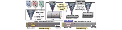
This study investigated cracking phenomena in 316L stainless steel (SS316L) and Inconel 718 (IN718) composition-graded material (CGM) additively manufactured by the direct energy deposition (DED) process. In order to prevent cracking in the CGM, thermodynamic analysis was performed to avoid the critical concentration for crack formation. Based on the local compositional detouring (LCD) method suggested by new approach, a crack-free CGM with a nonlinear combination of SS316L and IN718 was successfully fabricated with local additional elemental powder in the CGM defective region obtained using a multi-powder feeding system during the DED process.
GRAPHICAL ABSTRACT
IMPACT STATEMENT
We aim to avoid the cracks of functionally graded materials fabricated by local in-situ alloying technique using the result of thermodynamically analyzing.
1. Introduction
Metal additive manufacturing (MAM), also called metal three-dimensional (3D) printing, has led a global manufacturing trend by opening a new window for producing multi-functional complex geometry products [Citation1–6]. Among the various MAM techniques, the directed energy deposition (DED) process, in which powder is sprayed into a melt pool with scanning of a high-energy beam (e.g. laser beam), has recently attracted considerable attention. In particular, the fabrication of functionally graded materials (FGMs) in various compositions is possible using a DED machine equipped with multiple powder feeders [Citation7–11]. Therefore, numerous scientists have attempted to fabricate composition graded materials (CGMs) with various material combinations to obtain a multi-functional product with unique performance [Citation7–16]. In particular, the expected performance of the combination of austenitic stainless steels and austenitic nickel-based superalloys includes good mechanical properties at high temperatures, excellent corrosion resistance, and outstanding mechanical properties at cryogenic temperatures (e.g. nuclear reactors, aerospace, and offshore plants) [Citation7–11,Citation17–21]. On the other hand, intermetallic compound (IMC)-induced cracking has been often reported for DED-processed CGMs because the DED process generates a compositional gradient region at the interface from the complete melting of different materials [Citation17–19,Citation22,Citation23]. However, it has been reported that the avoidance of cracking is still difficult when using only a linear combination of nickel-based superalloy and stainless steels [Citation17–20,Citation24]. To develop a new strategy for avoiding cracking in nickel-based superalloy and stainless steel CGMs, the crack formation mechanism has been systematically explored both experimentally and theoretically in this study.
2. Experimental
A DED machine (MX-lab, InssTek Co., Republic of Korea) equipped with multi-powder feeders was used for the production of CGM in various configurations [Citation25,Citation26]. The rectangular blocks were deposited using SS316L (austenitic stainless steel ASTM 316L) and IN718 (austenitic nickel-based superalloy Inconel 718) powders on an SS316L substrate (see the schematic of the process in (a)). In order to fabricate a sample with gradient composition, the SS316L and IN718 powders were simultaneously sprayed from the powder nozzle while the volume fraction of IN718 powder was linearly increased during 54 layers from 0% at the bottom to 100% at the top. The length and width of the sample were 30 and 6 mm, respectively. For microstructure characterization, X-ray diffraction (XRD) analysis, Optical microscopy (OM) images, field-emission scanning electron microscopy (FE-SEM) equipped with energy-dispersive spectroscopy (EDS) and backscattered electron (BSE) detectors and electron backscatter diffraction (EBSD) analysis was conducted. The compositions of materials, DED processing conditions, and microstructure characterization details can be found in Supplemental Information.
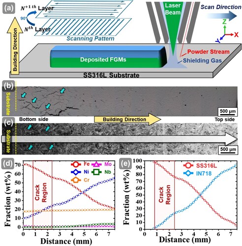
Figure 1. (a) Schematic of the DED process for CGM fabrication; (b) OM, (c) SEM, (d) EDS line profile, and (e) estimated concentration ratio of SS316L and IN718 CGM fabricated using the DED process. In this study, the longitudinal direction is denoted as X, the transverse direction is denoted as Y, and the fabrication direction is denoted as Z.
3. Results and discussion
(b) presents OM and SEM-BSE micrographs with EDS elemental analysis on the transverse section (Y plane) of the as-fabricated sample. As shown in (c), the grains were epitaxially grown along the building direction of the CGM. When the fraction of IN718 was increased along the building direction, the contrast of the SEM-BSE micrographs became brighter. This increase in brightness is attributed to a concentration of relatively heavy elements with the presence of secondary phases in IN718 compared to those in the SS316L [Citation21,Citation27,Citation28]. In order to measure the chemical composition distribution in the building direction of the sample, an EDS line profile was acquired along the white arrow in the SEM micrographs ((c)), as shown in (d). The Fe concentration linearly decreases and the Ni concentration linearly increases with increasing distance from the substrate along the building direction. Based on the elemental distribution measured in the EDS analysis, the variation of the fraction of SS316L and IN718 contents in the building direction could be calculated as indicated in (e). It can be clearly observed that the composition-graded sample was well fabricated with a gradual layer-by-layer increase of IN718 fraction using a DED process with multi-powder feeders.
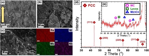
Figure 2. SEM micrographs obtained from the crack region at various magnifications: (a) the crack zone cracks are indicated by white arrows, building direction are indicated by yellow arrows, (b) cell structure and secondary phases, (c) SEM and EDS results obtained at high magnification. (d) XRD pattern of the CGM fabricated by the DED process and (e) a resized XRD pattern to clearly show secondary phases.
Meanwhile, as indicated by blue arrows in the OM ((b)) and SEM images ((c)), large cracks within a submillimeter length are observed at the bottom region of the as-fabricated sample, near the substrate. These micro-cracks are detected in the SS316L-rich region of the composition-graded sample while it is difficult to find any cracks in the middle and top regions of the samples. In other words, cracking occurs at a specific composition range in the gradient composition of the SS316L and IN718 mixture, and sound microstructure can be obtained without crack formation when the fraction of IN718 content is increased over a critical amount. The composition range of Fe in the crack formation region was measured to range from ∼58 to ∼66 wt%, which could be used to determine the range of SS316L content in the composition-graded sample: ∼78 to ∼98 wt%. The results also demonstrate that the secondary phase in a specific composition range (SS316L of ∼80–96 wt%) was more harmful than those in the other composition range. In the current work, we have confirmed the critical composition range in which the intermetallic formation causes cracking. Further, to solve the cracking problem, a technique for local in-situ control of chemical composition is proposed. Importantly, crack-free FGM of SS316L/IN718 was successfully produced by changing the composition in real-time only in the specific region where cracking was induced.
presents magnified SEM micrographs in the CGM crack region. It can be clearly observed in these micrographs that the cracks mainly propagate along the grain boundaries and cell boundaries in the fabrication direction. Meanwhile, as shown in (b), the secondary phases with white contrast in the SEM-BSE image have spherical or long-chain shapes along the crack surface and strongly imply that cracking could be induced by a secondary phase in the mixed SS316L and IN718. (c) shows SEM-BSE images combined with EDS mapping for the CGM crack region. Noticeably, an abundant enrichment of Mo and Nb content is observed in the secondary phases along the crack lines.
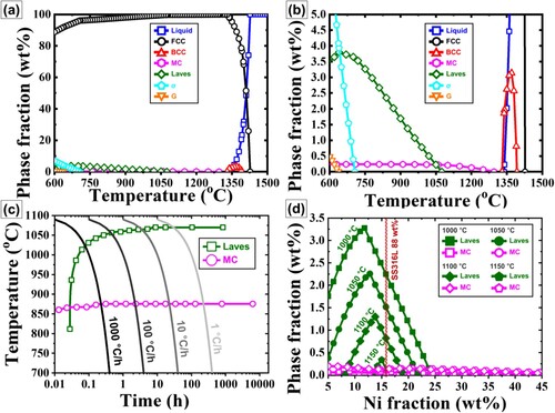
In order to understand the evolution of the secondary phase in the CGM cracking region, a thermodynamic calculation was conducted using the CALPHAD software (JMatPro® 7.0, Sente Software Ltd, UK, NiFe-based superalloy database). presents the equilibrium phase fraction with temperature at the chemical composition of the median composition of the CGM crack formation region (88-wt% SS316L and 12-wt% IN718). The secondary phases could be identified under a wide temperature range at the crack formation region composition. For a temperature range of 600–1300°C, NbC monocarbides (MCs) are found. The presence of MC-type carbide is often reported for additively manufactured IN718 alloys [Citation29,Citation30]. Moreover, it has been often reported that NbC carbide has high Mo solubility over a wide temperature range: NbC carbide could also involve the Mo contents as (Nb, Mo)C carbide [Citation17–19,Citation29,Citation30]. Below 1080 °C, precipitation of an Nb- and Mo-rich Laves phase is observed, and the fraction of the Laves phase increases when temperature decreases from 1080 to 640 °C. Meanwhile, the temperature range of the Laves phase and the NbC was obviously extended at the crack region of the CGM as compared to the case of IN718 alone [Citation24]. This demonstrates that the precipitation of brittle Laves phase and NbC is more preferential in the SS316L-enriched CGM composition than in those of the IN718 region and could highly promote the cracking at the SS316L-enriched region.
Figure 3. (a) Equilibrium phase fraction with temperature for a wt% ratio 88:12 (SS316L:IN718), (b) the magnified view of (a) to clearly show minor phases, (c) CCT curves as a function of time and temperature for a wt% concentration ratio of 88:12 (SS316L:IN718) and (e) fraction of secondary phases to Ni concentration considering the temperature of the CGM fabricated by the DED process.
(d, e) shows the XRD patterns obtained from the crack region of the CGMs. When identifying the XRD peaks, high-temperature stable phases (Laves phase and NbC) are detected in the face-centered cubic (FCC) matrix of the CGM. The XRD peak of Cr23C6 carbide could be mainly detected in the SS316L-side of the CGM, which was previously reported for additively manufactured austenitic stainless steel due to sensitization at a wide temperature range [Citation24]. It has been widely reported that DED-processed materials produce high-temperature-stable microstructure [Citation18,Citation31]. During DED, solidification occurs in the melt pool with a tremendously high cooling rate (102–104 K/s) after the melt pool is exposed to the laser beam [Citation32,Citation33]. Therefore, high-temperature-stable microstructure could be obtained under rapid solidification in DED-processed materials [Citation17,Citation34]. Moreover, an in-situ heat treatment affects phase transformation during additive manufacturing since the heat flux is repeatedly transferred from adjoining regions to the substrate, allowing for low-temperature stable phases to be dissolved [Citation35–37]. It has been suggested that representative temperatures should be considered for the phase evolution behavior of samples fabricated by DED. Carrol et al. [Citation17] investigated crack formation in a DED-processed CGM having three sections of SS304L, a gradient zone, and IN625 along the building direction. They found secondary-phase-induced cracking near the starting region of the gradient zone (approximately 82-wt% SS304L) and in the SS304L part, similar to our results. They supposed a representative temperature range of 950–1100 °C for the phase evolution behavior in CGMs during the DED process. In addition, they observed that high-temperature-stable precipitates remained in the as-fabricated CGMs. On the assumption of a representative temperature range of 950–1100 °C, the brittle phases (NbC, Laves phase) are dominant secondary phases in their CGMs. Furthermore, Nb is segregated at the cell boundaries because Nb atoms were ejected from liquid to solid during solidification [Citation38,Citation39]. This segregation can highly promote the formation of brittle Laves phase or NbC carbide in the samples.
(c) presents continuous cooling transformation (CCT) curves at a starting temperature of 1100 °C and a CGM wt% composition ratio of 88:12 (SS316L:IN718). Although both the NbC and the Laves phase coexist in the composition of the cracking region in the CGMs, formation of the Laves phase appears to be predominant compared with the formation of NbC carbide. Therefore, the major cracking factor at the transition region in the CGMs could be due to the Laves phase, which is widely known as the brittle phase in IN718 alloy [Citation38,Citation40]. (d) shows variations of Laves phase and MC carbide fractions with increasing Ni content at a temperature range of 1000–1150 °C. Noticeably, the maximum peaks of the Laves phase fraction are located at a Ni fraction ranging from 12 to 15 wt%, which corresponds with IN718 fractions ranging from ∼5 to ∼10 wt%. The composition range of the CGM cracking regions is well matched. Furthermore, the Ni composition range (∼12–25 wt%) accompanying the precipitation of the Laves phase in (d) is in good agreement with the crack formation region indicated by the red box in (d). When the Ni fraction increases beyond the maximum peak of the Laves phase fraction, the Laves phase fraction rapidly decreases. This strongly implies that the formation of the Laves phase is a key factor for the cracking phenomenon observed at a specific SS316L and IN718 composition range. Meng et al. [Citation41] recently investigated the phase evolution behavior in a DED-processed CGM of SS316L and IN625. They observed that the precipitated phases were transformed from FCC + Laves to FCC + NbC phases when increasing IN625 contents over 50 wt% in the CGM. Their observation is quite similar to our theoretical and experimental results. This strongly supports that the cracking mainly occurs due to the profuse evolution of the brittle Laves phase at the SS316L-rich region in the composition-graded region of the CGM. In addition, to understand the cracking during solidification, a Scheil-Gulliver solidification simulation that effectively calculates the solute elements’ segregations during the solidification was performed [Citation42–46]. The Scheil-Gulliver solidification simulations at the composition ratio of 88:12 (SS316L:IN718 in wt%) of FGM results in the conclusion that the Laves phase is the cause of the cracking (Figure S4). Moreover, it could be suggested that crack formation was suppressed by an increase in Ni contents that reduced the fraction of the Laves phase. It is well known that Laves phase, or Nb-rich phase ((Ni, Cr, Fe)2 (Nb, Mo, Ti, Si)), is a brittle intermetallic compound. Since austenitic stainless steels are susceptible to solidification cracking, small amounts of Laves could be sufficient to cause crack formation in the SS316L-rich region [Citation18,Citation19].
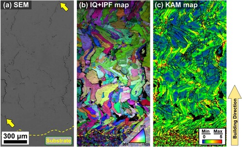
Furthermore, the high thermal residual stress during the DED process evolves due to the complex thermal cycle with ultrafast heating and cooling [Citation32,Citation33]. In particular, severe thermal residual stress could arise in the CGM sample due to the difference in thermal expansion coefficient between SS316L and IN718. presents EBSD maps of the CGM crack regions. The cracks are mainly located at the grain and cell boundaries. Local strains are abundantly accumulated at the crack surface, as indicated in (c). It has been reported that the strain accumulation during solidification could be catastrophic from the perspective of dislocation migration at grain boundaries [Citation17–19,Citation22–24,Citation47]. When the thermal-induced tensile stress exceeds the yield stress of a local region, dislocation slip could lead to dislocation pile-up at the grain boundaries having long chains of hard laves phase [Citation43], which promotes the tensile residual stress normal to the boundaries and accelerates cracking [Citation44–48]. This can be inferred from the high kernel average misorientation (KAM) value concentrated at the cracked grain boundaries (c).
Figure 4. SEM-EBSD maps of crack zones: (a) SEM micrograph showing cracks in the composition range between (SS316L ∼2 to ∼24 wt%), with yellow arrows showing the cracks. (b) The inverse pole figure map of the region shown in (a) indicates that the cracks formed along the grain boundary; (c) the corresponding KAM map shows that the crack regions have high KAM values.
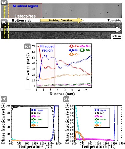
On the other hand, residual thermal stresses and the formation of brittle Laves phase are inevitable in a CGM because critical concentrations will always exist when using only a linear combination of IN718 and SS316L powders [Citation17]. Therefore, a potential approach to reduce the cracking in the CGM could be modifying the composition by using more powder feeders to suppress the formation of the Laves phase. Based on these results and analysis, A new additive manufacturing strategy, local compositional detouring (LCD), is introduced. The key of strategy is to avoid cracking factors by in-situ changing the local chemical composition during additive manufacturing. In order to verify the possibility of suppression of Laves-phase-induced cracking based on our thermodynamic study, pure Ni was simultaneously added to the SS316L-rich region from the substrate to the region with 70-wt% SS616L in the CGM. Cross-sectional micrographs (Y plane) with EDS line profile results for the Ni-added CGM are shown in . Strikingly, a crack-free sample was obtained by in-situ addition of Ni powder to the CGM. (c) indicates EDS line profile results for the pure Ni-added CGM. Based on the thermodynamic calculation ((d)), when the Ni composition exceeds 25 wt% at the crack region in the SS316L and IN718 CGM, the precipitation of Laves phase is suppressed and the NbC phase is the dominant Nb-rich precipitate. For the pure Ni-added samples, the Ni composition was over 25 wt% at the crack-sensitive region and there were no observable cracks in the samples (). The EDS results at the same location studied in the cracked FGM are Ni: 48.92, Fe: 33.68, Cr: 13.15, Mo: 0.772, and Nb: 0.982. Thermodynamic phase calculations at this composition are shown in (d, e). Compared to Figures (a, b), (Nb, Mo)C type carbides are present in a smaller fraction in all temperature ranges, and the laves phase is formed below 700 °C. In other words, the local Ni addition can effectively suppress the laves phase and effectively avoid the cause of crack formation. This demonstrates that the local addition of elemental powder using multi-powder feeders to vary the composition (compositional detouring method) is an effective crack-mitigation strategy for avoiding the critical concentration with respect to the precipitation of the harmful phase in the DED-fabricated CGM.
Figure 5. (a) OM, (b) SEM, and (c) corresponding EDS line profile results of the pure Ni-added CGM fabricated by in-situ alloying. Due to the local in-situ alloyed Ni, the local composition was changed and cracks disappeared (compared with the crack zone in ). (e) Equilibrium phase fraction with temperature for defect-free FGM at 12 wt% IN718, (f) the magnified diagram to clearly show minor phases.
4. Conclusion
In summary, cracks in an SS316L and IN718 CGM fabricated using a single DED process, without prior alloy powder fabrication or prior powder mixing, were analyzed. The induced cracks were analyzed considering the mixed composition and the cause for cracking was determined to be the secondary phase formed during the DED process (solidification with rapid cooling). Furthermore, a new method for manufacturing defect-free CGM was proposed in consideration of the composition. The current work suggests the LCD method for manufacturing defect-free continuous CGMs in a single process using an in-situ alloying technique. Furthermore, this method can be adopted not only for CGMs of SS316L and IN718 but also for other material combinations wherein cracks are induced by the secondary phases during solidification. Also, this method does not require pre-powder mixing, which saves considerable time. In addition, because this method can manufacture defect-free parts with FGM by tailoring compositions of local regions only, material savings are also expected.
Supplemental Material
Download MS Word (2.9 MB)Acknowledgments
Eun Seong Kim was supported by the Basic Science Research Program ‘Fostering the Next Generation of Researchers (Ph.D. Candidate)’ through the NRF funded by the Ministry of Education (2022R1A6A3A13073830).
Data availability
The raw/processed data required to reproduce these findings cannot be shared at this time as the data also forms part of an ongoing study.
Disclosure statement
No potential conflict of interest was reported by the author(s).
Additional information
Funding
References
- Karthik GM, Kim HS. Heterogeneous aspects of additive manufactured metallic parts: a review. Met Mater Int. 2021;27(1):1–39.
- Bandyopadhyay A, Zhang Y, Bose S. Recent developments in metal additive manufacturing. Curr Opin Chem Eng. 2020;28:96–104.
- DebRoy T, Wei HL, Zuback JS, et al. Additive manufacturing of metallic components – Process, structure and properties. Prog Mater Sci. 2018;92:112–224.
- Gorsse S, Hutchinson C, Gouné M, et al. Additive manufacturing of metals: a brief review of the characteristic microstructures and properties of steels, Ti-6Al-4V and high-entropy alloys. Sci Technol Adv Mater. 2017;18(1):584–610.
- Park JM, Asghari-Rad P, Zargaran A, et al. Nano-scale heterogeneity-driven metastability engineering in ferrous medium-entropy alloy induced by additive manufacturing. Acta Mater. 2021;221:117426.
- Park JM, Kim ES, Kwon H, et al. Effect of heat treatment on microstructural heterogeneity and mechanical properties of 1%C-CoCrFeMnNi alloy fabricated by selective laser melting. Addit Manuf. 2021;47:102283.
- Zhang C, Chen F, Huang Z, et al. Additive manufacturing of functionally graded materials: a review. Mater Sci Eng A. 2019;764:138209.
- Son JY, Yoon HS, Lee KY, et al. Investigation into high-temperature interfacial strength of heat-resisting alloy deposited by laser melting process. Met Mater Int. 2020;26(3):384–394.
- Saleh B, Jiang J, Fathi R, et al. 30 Years of functionally graded materials: an overview of manufacturing methods, Applications and Future Challenges. Composites, Part B. 2020;201:108376.
- Wu H, Chen S, Zhang C, et al. Layered 50Cr6Ni2/stellite X-40 multi-material fabricated by direct laser deposition: characterization and properties. Met Mater Int. 2021;27(1):40–49.
- Guo M, Chen S, Shang F, et al. Laser cladding novel NiCrSiFeBW–CeO2 coating with both high wear and corrosion resistance. Met Mater Int. 2021;27(8):2706–2719.
- Bohidar SK, Sharma R, Mishra PR. Functionally graded materials: a critical review. Int J Res. 2014;1(4):289–301.
- Studart AR. Biological and bioinspired composites with spatially tunable heterogeneous architectures. Adv Funct Mater. 2013;23(36):4423–4436.
- Chen P-Y, McKittrick J, Meyers MA. Biological materials: functional adaptations and bioinspired designs. Prog Mater Sci. 2012;57(8):1492–1704.
- Meyers MA, McKittrick J, Chen P-Y. Structural biological materials: critical mechanics-materials connections. Science. 2013;339(6121):773–779.
- Yu Q, Huang Z, Zheng G, et al. Thermal Shock Behavior of a Novel TiCx–Ni3(Al,Ti)/Ni Functionally Graded Composite. Met Mater Int. 2021;27(12):5133–5144.
- Carroll BE, Otis RA, Borgonia JP, et al. Functionally graded material of 304L stainless steel and inconel 625 fabricated by directed energy deposition: characterization and thermodynamic modeling. Acta Mater. 2016;108:46–54.
- Chen N, Khan HA, Wan Z, et al. Microstructural characteristics and crack formation in additively manufactured bimetal material of 316L stainless steel and Inconel 625. Addit Manuf. 2020;32:101037.
- Mei X, Wang X, Peng Y, et al. Interfacial characterization and mechanical properties of 316L stainless steel/inconel 718 manufactured by selective laser melting. Mater Sci Eng A. 2019;758:185–191.
- Dev S, Ramkumar KD, Arivazhagan N, et al. Investigations on the microstructure and mechanical properties of dissimilar welds of inconel 718 and sulphur rich martensitic stainless steel, AISI 416. J Manuf Process. 2018;32:685–698.
- Devendranath Ramkumar K, Patel SD, Sri Praveen S, et al. Influence of filler metals and welding techniques on the structure–property relationships of Inconel 718 and AISI 316L dissimilar weldments. Mater Des (1980-2015). 2014;62:175–188.
- Reichardt A, Dillon RP, Borgonia JP, et al. Development and characterization of Ti-6Al-4V to 304L stainless steel gradient components fabricated with laser deposition additive manufacturing. Mater Des. 2016;104:404–413.
- Bobbio LD, Otis RA, Borgonia JP, et al. Additive manufacturing of a functionally graded material from Ti-6Al-4V to Invar: experimental characterization and thermodynamic calculations. Acta Mater. 2017;127:133–142.
- Sagong MJ, Kim ES, Park JM, et al. Interface characteristics and mechanical behavior of additively manufactured multi-material of stainless steel and Inconel. Mater Sci Eng A. 2022;847:143318.
- Kim ES, Haftlang F, Ahn SY, et al. Effects of processing parameters and heat treatment on the microstructure and magnetic properties of the in-situ synthesized Fe-Ni permalloy produced using direct energy deposition. J Alloys Compd. 2022;907:164415.
- Lee Y, Li S, Kim ES, et al. Transformation-induced plasticity in the heterogeneous microstructured Ti-Zr-Nb-Sn alloy via in-situ alloying with directed energy deposition. Addit Manuf. 2022;58:102990.
- Timischl F, Inoue N. Increasing compositional backscattered electron contrast in scanning electron microscopy. Ultramicroscopy. 2018;186:82–93.
- Yasseri M, Farahi N, Kelm K, et al. Rapid determination of local composition in quasi-binary, inhomogeneous material systems from backscattered electron image contrast. Materialia. 2018;2:98–103.
- Wang K, Liu Y, Sun Z, et al. Microstructural evolution and mechanical properties of Inconel 718 superalloy thin wall fabricated by pulsed plasma arc additive manufacturing. J Alloys Compd. 2020;819:152936.
- Yesim Yalcin M, Bora D, Aydogan E. Development and additive manufacturing of oxide dispersion strengthened inconel 718: thermochemical and experimental studies. J Alloys Compd. 2022;914:165193.
- Barr C, Da Sun S, Easton M, et al. Influence of delay strategies and residual heat on in-situ tempering in the laser metal deposition of 300M high strength steel. Surf Coat Technol. 2020;383:125279.
- Lee HT, Chen CT. Numerical and experimental investigation into effect of temperature field on sensitization of AISI 304 in butt welds fabricated by Gas tungsten Arc welding. Mater Trans. 2011;52(7):1506–1514.
- Biegler M, Graf B, Rethmeier M. In-situ distortions in LMD additive manufacturing walls can be measured with digital image correlation and predicted using numerical simulations. Addit Manuf. 2018;20:101–110.
- Liu Z-K. Thermodynamic calculations of carbonitrides in microalloyed steels. Scr Mater. 2004;50(5):601–606.
- Li Y, Wu S, Li H, et al. Submerged arc additive manufacturing (SAAM) of low-carbon steel: effect of in-situ intrinsic heat treatment (IHT) on microstructure and mechanical properties. Addit Manuf. 2021;46:102124.
- Sames WJ, Unocic KA, Helmreich GW, et al. Feasibility of in situ controlled heat treatment (ISHT) of Inconel 718 during electron beam melting additive manufacturing. Addit Manuf. 2017;13:156–165.
- Li D, Huang H, Chen C, et al. Additive manufacturing of high strength near β titanium alloy Ti-55511 by engineering nanoscale secondary α laths via in-situ heat treatment. Mater Sci Eng A. 2021;814:141245.
- Xiao H, Li S, Han X, et al. Laves phase control of Inconel 718 alloy using quasi-continuous-wave laser additive manufacturing. Mater Des. 2017;122:330–339.
- Ye X, Zhang P, Zhao J, et al. Effect of macro- and micro-segregation on hot cracking of Inconel 718 superalloy argon-arc multilayer cladding. J Mater Process Technol. 2018;258:251–258.
- Sui S, Chen J, Fan E, et al. The influence of Laves phases on the high-cycle fatigue behavior of laser additive manufactured Inconel 718. Mater Sci Eng A. 2017;695:6–13.
- Meng W, Zhang W, Zhang W, et al. Fabrication of steel-Inconel functionally graded materials by laser melting deposition integrating with laser synchronous preheating. Opt Laser Technol. 2020;131:106451.
- Bobbio LD, Bocklund B, Simsek E, et al. Design of an additively manufactured functionally graded material of 316 stainless steel and Ti-6Al-4V with Ni-20Cr, Cr, and V intermediate compositions. Addit Manuf. 2022;51:102649.
- Moustafa AR, Durga A, Lindwall G, et al. Scheil ternary projection (STeP) diagrams for designing additively manufactured functionally graded metals. Addit Manuf. 2020;32:101008.
- Okugawa M, Izumikawa D, Koizumi Y. Simulations of Non-equilibrium and equilibrium segregation in nickel-based superalloy using modified scheil-gulliver and phase-field methods. Mater Trans. 2020;61(11):2072–2078.
- Martin JH, Yahata BD, Hundley JM, et al. 3D printing of high-strength aluminium alloys. Nature. 2017;549(7672):365–369.
- Keller T, Lindwall G, Ghosh S, et al. Application of finite element, phase-field, and CALPHAD-based methods to additive manufacturing of Ni-based superalloys. Acta Mater. 2017;139:244–253.
- Lippold JC. Welding metallurgy and weldability. Hoboken (NJ): Wiley; 2014.
- Kong D, Dong C, Ni X, et al. High-throughput fabrication of nickel-based alloys with different Nb contents via a dual-feed additive manufacturing system: effect of Nb content on microstructural and mechanical properties. J Alloys Compd. 2019;785:826–837.