
 ?Mathematical formulae have been encoded as MathML and are displayed in this HTML version using MathJax in order to improve their display. Uncheck the box to turn MathJax off. This feature requires Javascript. Click on a formula to zoom.
Abstract
A novel type of austenite–martensite dual-phase laminate steel with a yield strength of 2.2 GPa, ultimate tensile strength of 2.5 GPa, uniform elongation of 9.4% and total elongation of 12% was produced. Such unexpectable mechanical properties were mainly due to the synergistic strengthening of nanolaminate microstructure, high densities of dislocations and nanoprecipitates. The high uniform elongation at very high stress could be attributed to the strongly enhanced work hardening rate, mainly enabled by transformation-induced plasticity (TRIP) of the austenite reverted by annealing, as well as the cooperative deformation and stress/strain partitioning between the austenite–martensite stacked nanolaminate.
GRAPHICAL ABSTRACT
IMPACT STATEMENT
This work verifies an effective strategy of combining TRIP and maraging to achieve both ultrahigh strength and high ductility of steel.
1. Introduction
Steels and alloys with both extremely high yield strength (YS) exceeding 2 GPa and good ductility attracted extensive attention recently [Citation1–5]. These unexpectable mechanical properties give promising materials for the solution of weight lightening, energy saving, as well as safety requirement, which have important technological applications in the engineering fields of aerospace and energy. Martensitic steels have very high strength above 1 GPa, due to the fine martensite lathes and high dislocation density. When submitting the martensite to aging treatment, massive nanosized precipitates are formed in martensite lathes. The precipitates act as effective obstacles to the dislocation motion, thereby enhancing the YS of steels further up to 2 GPa [Citation1,Citation5,Citation6]. However, the significant increase in YS is usually accompanied by a drop in ductility, particularly the uniform tensile elongation, because the steels have lost strain hardening capability [Citation1,Citation5,Citation6].
In order to improve the ductility of martensitic steels without sacrificing strength, a new design strategy was proposed, i.e. combining transformation-induced plasticity (TRIP) and martensite aging (maraging) effect in one steel [Citation7–12]. Accordingly, the steel is called TRIP-maraging steel. In this kind of steel, fine austenite grains are partially reverted from the martensite, while nanosized intermetallic precipitates are formed in the martensitic matrix during ageing treatment. This complex microstructure has three typical effects named the TRIP effect, the maraging effect and the synergetic effect of austenite–martensite composite structure, which can work concurrently in one steel. The simultaneous improvement of both YS and ductility has been experimentally verified in several TRIP-maraging steels. For instance, introducing 15 vol.% retained austenite into age-hardened martensite led to 1.3 GPa tensile strength and 21% total elongation in a 12 wt.% Mn steel [Citation7]. Besides, the austenite–martensite composite microstructure exhibits strong strain partitioning by deformation-induced phase transformation and mechanical twinning, and can enhance the damage resistance of TRIP-maraging steel [Citation12,Citation13].
To date, significantly improving the ductility of 2 GPa steel is still a great challenge, although engineering extremely high dislocation density and TRIP effect had achieved this aim [Citation2]. In this work, applying the TRIP-maraging strategy we fabricate an austenite–martensite nanolaminate steel, which shows great potential to break through the bottleneck of low ductility on extra-high YS of 2.2 GPa.
2. Materials and methods
The experimental steel, with a chemical composition in weight of 0.35% C, 8% Ni, 8% Cr, 4% Mo, 2% Mn, 2% Al, 0.1% V and 0.1% Nb, was melted in a vacuum induction furnace and then cast in a 25 kg ingot by a mold with a diameter of 110 mm. The cast ingot was then homogenized at 1200 °C for 6 h and forged into rods with a diameter of 30 mm; and cooled down to room temperature (RT). Then, another homogenization treatment was performed at 1100 °C for 2 h and the steel was quenched in water. Thereafter, a small plate in thickness of 10 mm was cut from the rod and rolled by multiple passes with a total reduction of ∼90% at RT. The cross-section size of the steel after rolling is 1 mm in thickness and 30 mm in width. The rolled samples were aged at 500 °C for 2 h followed by air cooling. Finally, intercritical annealing was conducted at 600 °C for 10 min followed by air cooling. The tensile specimens with a gauge size of 1 × 2 × 10 mm3 were cut along the rolling direction. Uniaxial tensile tests were carried out at a strain rate of 5 × 10⁻⁴ s−1 at RT. The microstructures were characterized on a FEI G2 F20 transmission electron microscope (TEM). TEM foils were obtained by carefully polishing the specimens to a thickness of ∼50 µm, and then further thinning by ion beam milling. The phase composition and dislocation density were measured by using X-ray diffractometer (XRD) with a Co Kα radiation, in a scanning range from 40° to 110° with a step of 0.01°. Atom-scale element partitioning among the phases was investigated by employing atom probe tomography (APT). The APT characterizations were performed on a Cameca LEAP 5000XR instrument in high-voltage mode at 60 K with an amplitude of 15% of the applied direct-current voltage and a repetition rate of 200 kHz. Cameca IVAS 3.8 was used to recover the APT data.
3. Results and discussion
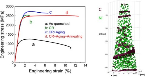
(a) shows the tensile engineering stress–strain curves of the studied steel in different states. The sample in as-quenched state has a low YS of 990 MPa, an ultimate tensile strength (UTS) of 1261 MPa, and a low tensile elongation (TE) of 11%. 90% Cold rolling increases the YS to 2261 MPa and the UTS to 2539 MPa, whereas the TE drops to ∼3%. By aging treatment at 500 °C for 2 h, the YS of the steel is further elevated to 2518 MPa and the UTS is raised to 2734 MPa, while the TE is recovered to ∼6%.
Figure 1. Tensile behaviors of the studied steel. (a) Engineering stress–strain curves of the steels in different states. (b) True stress–strain curves and strain hardening behaviors of the experimental steel.
The final intercritical annealing leads to the YS of 2251 MPa, the UTS of 2513 MPa and the TE higher than 12% together with a uniform elongation of 9.4%, which produces an excellent product of strength-to-ductility of about 30 GPa%. This unexpectable combination of extra-high strength and good ductility, in particularly the high uniform elongation, is much superior to many other ultrahigh strength steels at the same YS level [Citation1,Citation3,Citation5,Citation6]. It is obvious that the high strain hardening regained during intercritical annealing contributes to the substantial increase in ductility. As shown in (b), a hardening trend governed by the TRIP effect is presented, in which the strain hardening rate drops firstly and thereafter gradually climbs with increasing strain. Obviously, the TRIP effect is the most fundamental reason why the studied steel retains its ductility.
Figure 2. Typical lamellar microstructure in the sample after aging and intercritical annealing treatment. (a) and (b) Bright- and dark-field TEM images, respectively. (c) The distributions of layer thickness before and after tensile test. (d) HRTEM image showing austenite–martensite nanolamellar structure. (e) An enlarged HRTEM image from the area marked with white frame in (d). The inset is the corresponding SAD pattern with the zone axis [011]γ // [11]α. (f) HRTEM image showing SFs in austenite layer. The insets in the up-right and low-right corners are the corresponding FFT pattern and SFs, respectively.
![Figure 2. Typical lamellar microstructure in the sample after aging and intercritical annealing treatment. (a) and (b) Bright- and dark-field TEM images, respectively. (c) The distributions of layer thickness before and after tensile test. (d) HRTEM image showing austenite–martensite nanolamellar structure. (e) An enlarged HRTEM image from the area marked with white frame in (d). The inset is the corresponding SAD pattern with the zone axis [011]γ // [1¯11]α. (f) HRTEM image showing SFs in austenite layer. The insets in the up-right and low-right corners are the corresponding FFT pattern and SFs, respectively.](/cms/asset/c218e91a-6213-45e9-af7d-10676234b475/tmrl_a_2194910_f0002_oc.jpg)
To understand the unique tensile behaviors of the studied steel, the microstructures before and after tensile tests are carefully investigated. (a,b) shows the typical bright- and dark-field TEM images of the steel after intercritical annealing. The microstructure is characterized by a lamellar structure. It is measured that the average spacing of the lamellae is about 277 nm, as shown in (c). Tensile deformation does not change the layer spacing significantly. In comparison with the martensitic microstructure in as-quenched state (Fig. S1), cold-rolling together with subsequent aging and annealing treatment has substantially changed the morphology, producing typical laminated microstructure ((a,b) and Fig. S2). Such microstructure with extremely thin laminates strengthens the steel significantly, as verified in (a). XRD measurements indicates that the volume fraction of austenite reverted from martensite is about 19.4% in the laminate (Fig. S3). As seen in (d), the austenite is also presented in very thin layers, and inserted into the martensite matrix to produce an austenite–martensite composite microstructure. The orientation relationship between austenite and martensite layers follows the Kurdjumov-Sachs (K-S) relation, i.e. (11
)γ// (
10)α and [011]γ// [
11]α, as verified by the corresponding selected-area diffraction (SAD) pattern in the inset of (e). Stacking faults (SFs) are occasionally observed within austenite lamella ((f)), possibly due to the high internal stress imposed by the neighboring highly strained martensite.
Figures (a,b) reveal typical precipitation inside martensite lath. The corresponding SAD pattern in the inset of (a) shows the super-structure diffraction spots from the B2 ordered precipitates, as marked with white circles. In the high-angle annular dark-field (HAADF) TEM image ((c)), high densities of spherical precipitates with a highly uniform distribution in martensite lath are observed. There are two types of precipitates in the steel, i.e. coherent and incoherent precipitates. The incoherent nanoparticles are probably carbides with diameter of 5–10 nm, as seen in (d). The coherent one is identified as B2 structured phase with much small size of 2–3 nm. (e) displays the high-resolution TEM (HRTEM) image of a coherent precipitation. The corresponding fast Fourier transform (FFT) pattern of the selected red area shows diffraction spots that are generated from the B2 ordered phase. The distribution of compositional elements is further investigated by EDS mapping. It is seen that the enrichment of Ni and Al is greater than that of other elements ((f)), further indicating that the small nanoparticles are B2 Ni/Al-rich structure.
Figure 3. Nanoprecipitation in the sample after aging and intercritical annealing treatment. (a) and (b) Typical bright- and dark-field TEM images, respectively, showing precipitation in the specific martensite lath. The inset in (a) is the corresponding SAD pattern with [001]α zone axis. The super-structure diffraction spots are marked with white circles. (c) A high density of spherical precipitates viewed by HAADF TEM. (d) The coherent and incoherent nanoprecipitates viewed in HRTEM image. (e) HRTEM image showing the precipitate with B2 structure. The inset is the FFT pattern of the area marked with red frame. The super-structure diffraction spots are marked with white circles. (f) Enrichment of Ni, Al in the martensite matrix detected by EDS.
![Figure 3. Nanoprecipitation in the sample after aging and intercritical annealing treatment. (a) and (b) Typical bright- and dark-field TEM images, respectively, showing precipitation in the specific martensite lath. The inset in (a) is the corresponding SAD pattern with [001]α zone axis. The super-structure diffraction spots are marked with white circles. (c) A high density of spherical precipitates viewed by HAADF TEM. (d) The coherent and incoherent nanoprecipitates viewed in HRTEM image. (e) HRTEM image showing the precipitate with B2 structure. The inset is the FFT pattern of the area marked with red frame. The super-structure diffraction spots are marked with white circles. (f) Enrichment of Ni, Al in the martensite matrix detected by EDS.](/cms/asset/798cfabb-cbf4-4587-ac04-c9b500063252/tmrl_a_2194910_f0003_oc.jpg)
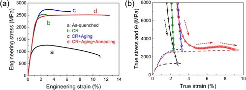
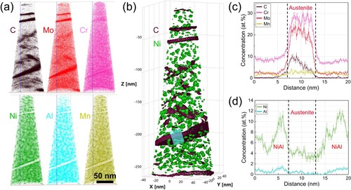
Details of the microstructure and elemental composition of the precipitates were further characterized by 3-D APT technique. Strong segregations of the main elements (C, Mo, Cr, Ni, Al and Mn) in the steel are visible, as shown in (a). The elements of C, Mo and Cr are abundant in the form of specific layers with no fixed stoichiometric ratio. On the other hand, the elements of Ni, Al and Mn show spherical distribution out of the specific layers. As shown in (b), the NiAl nanoparticles are randomly precipitated in the martensite matrix with an average diameter of about 2.2 nm. The number density of NiAl nanoparticles is about 4.3 × 10²³ m3, i.e. about 2.4% of volume fraction. Such high density of NiAl nanoparticles is similar to other type of maraging steels [Citation1,Citation5–7]. To further investigate the elements distribution, one of the APT datasets ((b)) is subjected to tomographic reconstruction, as presented in (c,d). It can be seen clearly that the elements of C, Cr and Mo are segregated to form austenite layer in a thickness of about 8 nm ((c)), which is in agreement with the TEM observation of austenite phase ((e)). The segregation of Ni and Al produces Ni/Al-rich precipitates.
Figure 4. 3-D APT analysis showing the tomography and chemical composition of austenite phase and precipitates. (a) C, Mo, Cr, Ni, Al and Mn atom maps in steel. (b) The tomographic reconstruction shows precipitates and lamellar austenite. (c) and (d) One-dimensional concentration profile of the cylindrical region highlighted in b, showing the enrichment of specific elements.
The compositions of Ni/Al-rich precipitates were obtained by using proximity histograms. It is revealed that all precipitates, regardless of their sizes, shapes or nucleation sites, are chemically similar, with an average composition of 46.530.36 at.% Ni, 7.89
0.20 at.% Al, 9.97
0.13 at.% Mn and 33.01
0.34 at.% Fe. This confirms that the Al-atomic sites in the B2 structure are partially substituted by Mn and Fe, forming a B2 Ni (Al, Mn, Fe) phase. The high level of chemical interaction and good compatibility of Mn with the NiAl phase is the mechanism for Mn partitioning to the NiAl nanoparticles. As reported in the literature [Citation14], Mn is more energetically preferred to occupy the Al sublattice, which enhances the energy for the creation of NiAl nanoparticles in ferritic alloys. As a result, Mn partitioning significantly increases the density of NiAl nanoparticles while also refining particle size.
Based on the above microstructural observations, the contributions to the strength increment in the studied steel include solid solution elements (), boundary strengthening from very fine lamellae (
), high densities of dislocations (
) and nanoprecipitates (
). Using a linear combination of these strengthening processes, an overall yield strength of the studied steel can be evaluated as [Citation15]
(1)
(1)
where
is the lattice friction stress (50 MPa) of body centered cubic (BCC) iron. Based on the measurements of chemical composition, densities of dislocations and precipitates, and lamellar thickness (Table S1), the strengthening contributions in the steel after aging and annealing treatment are that the solid solute (
) contributes to YS is 223 MPa, the lamellar boundaries (
) 1200 MPa, the dislocations (
) 357 MPa and the nanoprecipitates (
) 505 MPa (Seeing supplementary materials). Obviously, the refined lamellae spacing contributes significantly to the YS. By introducing high densities of dislocations and nanoprecipitates into martensite phase, the YS is further elevated. The YS of the steel after aging and annealing treatment calculated by above equation is about 2335 MPa, which is close to the experimental value of 2251 MPa. For the cold rolling and rolling + aging states, the calculated YSs are also in line with experimental results (Table S2).
In addition to the extra-high strength, the studied steel displays strong abilities of uniform plastic deformation and TRIP-like strain hardening (). Therefore, we examine the microstructures after tension to find the proofs of deformation-induced phase transformation. In XRD measurements (Fig. S3), the volume fraction of austenite decreases from initial 19.4% to about 8.6% after tensile test, suggesting the transformation from austenite to martensite during tension. (a,b) shows the co-exist of deformation micro-twins and α’ martensite primes in size of about ten nanometers within austenite lamellae. According to the corresponding SAD pattern ((c)), the orientation relations among austenite, deformation twins and α’ martensite are [10]γ // [1
0]twin // [1
1]α’ and (111)γ // (
11) twin // (110)α’. This is the well-known K-S orientation relation that is usually observed in the deformation-induced phase transformation from austenite to martensite in iron alloys [Citation16–18]. (d) shows the growth of α’ martensite into austenite. In front of the martensite/austenite interface, many micro-twins and SFs are pre-produced. These deformation twins and SFs are formed on two different slip systems, as indicated in (e). It has been revealed that two shears by partial dislocations on two independent (111)γ planes produce BCC martensite phase, which prefers to occur at the intersections of deformation twins, shear bands, etc. [Citation16–18].
Figure 5. Microstructural characterization of the phase transformation from austenite to martensite after tensile deformation. (a) Bright-field and (b) dark-field TEM images showing deformation microtwins and α’ martensite primes, as indicated by white arrows. (c) The SAED pattern and indexed pattern (a) with [011]γ zone axis. (d) HRTEM image showing the martensite–austenite interface. Deformation twins and SFs are detected in front of α’ martensite. (e) Enlarged image of the area marked with white frame in (d).
![Figure 5. Microstructural characterization of the phase transformation from austenite to martensite after tensile deformation. (a) Bright-field and (b) dark-field TEM images showing deformation microtwins and α’ martensite primes, as indicated by white arrows. (c) The SAED pattern and indexed pattern (a) with [011]γ zone axis. (d) HRTEM image showing the martensite–austenite interface. Deformation twins and SFs are detected in front of α’ martensite. (e) Enlarged image of the area marked with white frame in (d).](/cms/asset/ae7a1b2d-56e0-44fb-adc4-dfadedcbe33f/tmrl_a_2194910_f0005_oc.jpg)
In the TRIP-maraging steels, the martensite phase with high density of nanoprecipitates is usually much harder than the soft austenite. Therefore, the dynamic stress and strain partitioning between these two phases are primarily needed during further deformation, otherwise microcracks will be nucleated at the phase interface [Citation19–21]. This process can be accomplished by the phase transformation, because the TRIP process can introduce strain gradient at phase boundaries and maintain the strain continuity of whole sample [Citation10,Citation21]. Furthermore, the nanolaminate morphology shows great capability of enhancing both strength and ductility by the synergic deformation of austenite/martensite layers under the assistant of TRIP effect. Based on the composite effect [Citation11,Citation22–25], the hard layers act as effective ‘barriers’ to the plastic deformation of the soft phase to ensure the achievement of extra-high yield strength. Meanwhile, the difference in lateral shrinkage between the hard and soft layers leads to mutual constraints between them, forming an elastic/plastic interaction and a later plastic stability/instability mutual constraint [Citation25–27]. These mutual restraints change the applied uniaxial stress state to a multiaxial state, which contributes to higher internal stress levels [Citation22,Citation28] and thus effectively promotes phase transformation. Such scene is as similar as that in heterostructured materials, in which strong hetero-zone interaction occurs during plastic deformation to produce hetero-deformation induced stress (including back stress in the soft layer and forward stress in the hard layer) [Citation23,Citation29]. This constraint and cooperative deformation of soft/hard zone (austenite/martensite nanolayers in the current steel) is ultimately manifested by an increase in strain hardening rate and a delay in strain concentration, resulting in good ductility at high strength.
4. Conclusion
In summary, a new nanolaminate steel with YS of 2.2 GPa, extra-high UTS of 2.5 GPa and high uniform elongation of 9.4% (TE of 12%) is obtained by means of TRIP-maraging conception. The ultrahigh strength can be mainly attributed to the synergetic strengthening of martensite/austenite nanolaminate structure, high-density dislocations and massive intermetallic nanoprecipitates. The good ductility is originated from the deformation-induced phase transformation from austenite to martensite, as well as the cooperative deformation of austenite/martensite nanolayers assisted by TRIP, which contributes to high strain hardening rate.
Supplemental Material
Download MS Word (172 MB)Disclosure statement
No potential conflict of interest was reported by the author(s).
Additional information
Funding
References
- Jiang S, Wang H, Wu Y, et al. Ultrastrong steel via minimal lattice misfit and high-density nanoprecipitation. Nature. 2017;544:460–464.
- He BB, Hu B, Yen HW, et al. High dislocation density–induced large ductility in deformed and partitioned steels. Science. 2017;357:1029–1032.
- Gao B, Lai Q, Cao Y, et al. Ultrastrong low-carbon nanosteel produced by heterostructure and interstitial mediated warm rolling. Sci Adv. 2020;6:eaba8169.
- Li H, Zong H, Li S, et al. Uniting tensile ductility with ultrahigh strength via composition undulation. Nature. 2022;604:273–279.
- Liu T, Cao Z, Wang H, et al. A new 2.4 GPa extra-high strength steel with good ductility and high toughness designed by synergistic strengthening of nano-particles and high-density dislocations. Scr Mater. 2020;178:285–289.
- Yang MX, Yang G, Liu ZD, et al. Significant enhancement of strength in a lamellar-type nanostructured maraging steel subjected to equal-channel angular pressing for 12 passes. Mater Sci Eng Struct Mater Prop Microstruct Process. 2012;550:429–433.
- Raabe D, Ponge D, Dmitrieva O, et al. Nanoprecipitate-hardened 1.5 GPa steels with unexpected high ductility. Scr Mater. 2009;60:1141–1144.
- Dmitrieva O, Choi P, Gerstl SSA, et al. Pulsed-laser atom probe studies of a precipitation hardened maraging TRIP steel. Ultramicroscopy. 2011;111:623–627.
- Raabe D, Sandlöbes S, Millán J, et al. Segregation engineering enables nanoscale martensite to austenite phase transformation at grain boundaries: a pathway to ductile martensite. Acta Mater. 2013;61:6132–6152.
- Wang M-M, Tasan CC, Ponge D, et al. Smaller is less stable: size effects on twinning vs. transformation of reverted austenite in TRIP-maraging steels. Acta Mater. 2014;79:268–281.
- Wang M-M, Tasan CC, Ponge D, et al. Nanolaminate transformation-induced plasticity–twinning-induced plasticity steel with dynamic strain partitioning and enhanced damage resistance. Acta Mater. 2015;85:216–228.
- Wang M-M, Tasan CC, Ponge D, et al. Spectral TRIP enables ductile 1.1 GPa martensite. Acta Mater. 2016;111:262–272.
- Zhang H, Sun M, Liu Y, et al. Ultrafine-grained dual-phase maraging steel with high strength and excellent cryogenic toughness. Acta Mater. 2021;211:116878.
- Jiao ZB, Luan JH, Miller MK, et al. Effects of Mn partitioning on nanoscale precipitation and mechanical properties of ferritic steels strengthened by NiAl nanoparticles. Acta Mater. 2015;84:283–291.
- Wang J-S, Mulholland MD, Olson GB, et al. Prediction of the yield strength of a secondary-hardening steel. Acta Mater. 2013;61:4939–4952.
- Olson G, Cohen M. Mechanism for strain-induced nucleation of martensitic transformations. J Common Met. 1972;28:107–118.
- Huang CX, Yang G, Gao YL, et al. Investigation on the nucleation mechanism of deformation-induced martensite in an austenitic stainless steel under severe plastic deformation. J Mater Res. 2007;22:724–729.
- Yang X-S, Sun S, Zhang T-Y. The mechanism of bcc alpha ‘nucleation in single hcp epsilon laths in the fcc gamma -> hcp epsilon -> bcc alpha’ martensitic phase transformation. Acta Mater. 2015;95:264–273.
- Ryu JH, Kim D-I, Kim HS, et al. Strain partitioning and mechanical stability of retained austenite. Scr Mater. 2010;63:297–299.
- Fujita N, Ishikawa N, Roters F, et al. Experimental-numerical study on strain and stress partitioning in bainitic steels with martensite-austenite constituents. Int J Plast. 2018;104:39–53.
- Xu SS, Li JP, Cui Y, et al. Mechanical properties and deformation mechanisms of a novel austenite-martensite dual phase steel. Int J Plast. 2020;128:102677.
- Mara NA, Beyerlein IJ. Review: effect of bimetal interface structure on the mechanical behavior of Cu-Nb fcc-bcc nanolayered composites. J Mater Sci. 2014;49:6497–6516.
- Zhu Y, Wu X. Heterostructured materials. Prog Mater Sci. 2023;131:101019.
- Wu X, Yang M, Yuan F, et al. Heterogeneous lamella structure unites ultrafine-grain strength with coarse-grain ductility. Proc Natl Acad Sci USA. 2015;112:14501–14505.
- Ma XL, Huang CX, Xu WZ, et al. Strain hardening and ductility in a coarse-grain/nanostructure laminate material. Scr Mater. 2015;103:57–60.
- Ma X, Huang C, Moering J, et al. Mechanical properties of copper/bronze laminates: role of interfaces. Acta Mater. 2016;116:43–52.
- Huang CX, Wang YF, Ma XL, et al. Interface affected zone for optimal strength and ductility in heterogeneous laminate. Mater Today. 2018;21:713–719.
- Wang Y, Yang M, Ma X, et al. Improved back stress and synergetic strain hardening in coarse-grain/nanostructure laminates. Mater Sci Eng Struct Mater Prop Microstruct Process. 2018;727:113–118.
- Zhu Y, Ameyama K, Anderson PM, et al. Heterostructured materials: superior properties from hetero-zone interaction. Mater Res Lett. 2021;9:1–31.