
Abstract
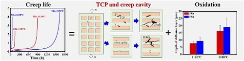
Ru is crucial in improving creep properties in Nickel-based single-crystal superalloys. The effect of Ru content on the creep behavior of nickel-based single-crystal superalloy was studied. Ru exhibits unprecedented mechanical properties, increasing the creep life at 1120 °C but decreasing it at 1180 °C. This is due to the competition in the stress concentration formed between the topologically close-packed phases and the creep cavity. They are both related to the dissociation of the γ′ phase. The effect of oxidation caused by the addition of Ru is lower than these two factors. This work helps to recognize the comprehensive effect of Ru and can provide guidance for alloy design in the future.
GRAPHICAL ABSTRACT
IMPACT STATEMENT
The study first revealed that adding Ru can reduce the creep life at high temperatures. The competition mechanism between the topologically closed-packed phase and the creep cavity is established.
1. Introduction
Nickel-based single-crystal superalloys are widely used for turbine blades [Citation1,Citation2]. When used in turbine blades, superalloys are subjected to continuous centrifugal forces and high temperatures. Therefore, creep resistance is important for these alloys [Citation3–5]. Among the alloying elements, Re and Ru are crucial elements used for this purpose [Citation6,Citation7]. Re is an effective strengthening element, with a 30 K increase in endurance temperature for 3 wt.% Re addition, as observed in the first three generations of superalloy. Ru is one of the defining elements that separates third from fourth generation superalloys. For example, the addition of 3 wt.% Ru is found to increase creep life at 1100 °C/137 MPa condition by 100%, from 164 h to 321 h [Citation8].
This is mainly due to its inhibiting the precipitation of topologically close packed (TCP) phases [Citation9]. The precipitation of the brittle TCP phases can significantly reduce the creep life [Citation10,Citation11]. The effect of Ru on inhibiting the precipitation of TCP phases is attributed to three main factors: (1) Ru improves the solid solubility of refractory elements[Citation12,Citation13], (2) Ru reduces the segregation coefficient of refractory elements between the γ and γ′ phases, a phenomenon known as the ‘reverse partition effect’ [Citation14], and (3) Ru increases the lattice strain energy of the TCP/γ phase interface [Citation15].
The commercial used second and third-generations Nickel-based superalloys typically serve at 1100 °C [Citation16]. With the addition of Ru, the endurance temperature of the alloys can be higher [Citation17,Citation18]. It is generally known that the γ′ phase dissolves, thus reducing its volume fraction at higher service testing temperatures [Citation19]. The dissolution of the γ′ phase will change the composition of the γ phase. More specifically, it will reduce the concentrations of the TCP phase-forming elements, thus lowering the tendency for their formation. In addition, Ru facilitates the growth of the oxide layer and results in the degradation of mechanical properties [Citation20,Citation21]. In summary, the effect of Ru in Nickel-based superalloys is complex and multi-faceted and varies with different testing (service) conditions. This work compares the creep life of two Nickel-based single-crystal superalloys with different Ru contents.
2. Experiment
The fourth-generation superalloy produced by the Beijing Institute of Aeronautical Materials is chosen as the base alloy. To investigate the effect of Ru content on the creep life, an alloy with different contents of Ru element was also adopted. Their nominal compositions are shown in Table , no minor elements were added in these two alloys, only containing different Ru contents, denoted 3Ru and 5Ru. The two alloys were fabricated by means of directional solidification investment casting into cylindrical single crystal bars of Φ16 mm × 75 mm with a [001] axial orientation. The bars were solution treated at 1345 °C for 4 h in argon atmosphere to dissolve the low-melting inter-dendrite eutectic structure into the matrix to ensure compositional homogeneity, followed by air cooling (AC) with the cooling rate of approximately 200 °C/min. After the solution treatment, the alloy was aged in two steps at 1120 °C/4 h (AC) followed by 870 °C/30 h (AC). The higher-temperature step encourages high-rate nucleation of the γ′ phase, and the lower-temperature step ensures the steady growth of the γ′ phase to achieve good cubicity and size uniformity. After the aging treatment, the 3Ru and 5Ru alloys were manufactured into samples in cylindrical dumbbell shape with a gauge section dimension of Φ5 × 27 mm and a [001] orientation along the axial direction. The creep tests were conducted under a 100 MPa tensile stress at two different temperatures: 1120 and 1180 °C. Study of microstructure and morphology using FEI Quanta 650F field emission scanning electron microscope operating at 20 kV, with a resolution of 1 nm. Scanning transmission electron microscopy (STEM) analysis was performed on a FEI Talos F2000X electron microscope (200 kV) equipped with an energy dispersive X-ray spectroscopy (EDS) spectrometer. Using a screening current of approximately 250 nA, with a magnification of approximately 230 k and a point resolution of approximately 0.25 nm, for 10 min for EDS collection. For quantitative EDS analysis, the Velox software equipped with an electron microscope is used to measure it.
Table 1. Nominal composition of experimental superalloy (wt. %).
3. Results and discussion
Figure (a) shows the creep lives of the two alloys tested at 1120 °C/100 MPa and at 1180 °C/100 MPa. The creep life is 888 h for the 3Ru alloy and 1628 h for the 5Ru alloy at 1120 °C. However, when the creep temperature increases to 1180 °C, the creep life is reduced to 139 h for the 3Ru alloy and 48 h for the 5Ru alloy. It is seen that the 5Ru alloy outperforms the 3Ru alloy in creep life at 1120 °C but underperforms it at 1180 °C. Figures (b) ∼ (e) show the relationship between creep strain rate and strain rate during the creep process, and the creep strain rate is denoted by its logarithmic values. It can be seen that all curves have three creep stages. The minimum creep rates of the two alloys are relatively close at 1120 °C. At 1180 °C, the creep rate of both alloys is higher than 1120 °C. And at this point, the 5Ru alloy exhibits a higher minimum creep rate.
Figure 1. Creep data of the 3Ru and 5Ru alloys creep tested at 1120 and 1180 °C under 100 MPa tensile load. (a) Creep lives of the 3Ru and 5Ru alloys; (b) ∼ (e) Strain rate versus strain curves of 3Ru and 5Ru alloys in different states.
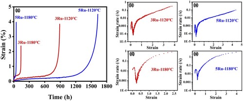
Figure shows the microstructures of the two alloys before and after the creep tests. Figures (a) and (b) are the initial microstructures of the 3Ru and 5Ru alloys before creep testing, respectively. They both consist of the standard γ′ cuboidal – γ channel microstructures. Figure (c) shows the size distributions of the γ′ cuboids in the two alloys. The average γ′ cuboid size is 307 nm for 3Ru and 249 nm for 5Ru. Figures (d) and (e) are the cross-section views of the microstructures of the samples after the creep test at 1120 °C/100 MPa. The samples were taken just under the creep surface within the necking zone. In the 3Ru alloy, needle-shaped precipitates of a TCP phase and some creep cavities have appeared within the γ′/γ matrix. In comparison, the 5Ru alloy contains only the creep cavities. The density of the creep cavities appears to be higher in the 5Ru alloy. The creep cavities are spatially distributed in three dimensions. Thus, they exhibit different contrast for the different magnitudes of secondary electrons for the various depth. And they are in sphere and square shape, which may be caused by the competition between the interface and strain energies during their formation. Figures (f) and (g) are the microstructures at a higher magnification of Figures (d) and (e), to show the TCP phases, the creep cavities and details of the γ′/γ matrix.
Figure 2. Microstructures of the two alloys under different conditions. (a) and (b) the 3Ru and 5Ru alloy in the initial state, respectively; (c) size distributions of the γ′ cuboids in the two alloys; (d) and (e) the 3Ru and 5Ru alloy after creep testing at 1120 °C/100 MPa, respectively; (f) and (g) the microstructures at a higher magnification of (d) and (e), respectively; (h) and (i) the 3Ru and 5Ru alloy after creep testing at 1180 °C/100 MPa; (j) and (k) volume fractions of the γ′ phase and densities of the creep cavity in the two alloys, respectively.
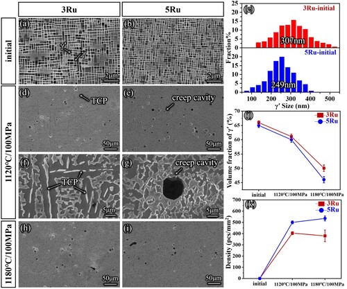
Figures (h) and (i) show the microstructures of the cross-section views of the samples after the creep test at 1180 °C/100 MPa. In this case, the TCP phases are only formed in the 3Ru alloy but in a lower volume fraction than at 1120 °C/100 MPa. The density of the creep cavities seems to be higher in the 5Ru alloy. Figure (j) shows the volume fractions of the γ′ phase in the two samples. The volume fraction of the γ′ phase decreased after the creep tests. The magnitude of the reduction is higher in the 5Ru alloy. Figure (k) shows the densities of the creep cavity in the samples. At both testing temperatures, the density is higher in the 5Ru alloy than in the 3Ru alloy.
The other sample of the 3Ru alloy was tested for 48 h at 1180 °C/100 MPa without creep. Figures (a) and (b) show the cross-section views of the microstructures of the two samples taken just under the necked regions. The 3Ru alloy exhibits TCP phases and creep cavities, whereas the 5Ru alloy shows only creep cavities. In addition, the density of the creep cavities is also much higher in the 5Ru alloy than in the 3Ru alloy. Figure (c) is the cross-section view of the microstructures of the sample taken at 6 mm below the fractured surface in 5Ru alloy. The density of the creep cavity is much lower than the region adjacent to the fracture, as shown in Figure (b). This indicates the creep cavity is promoted with higher deformation. Figure (d) shows EDS element mapping in one square-shaped creep cavity. There is no element segregation in the region. Figure (e) shows the volume fractions of the γ′ phase and the densities of the creep cavity. The reduction of the volume fraction of the γ′ phase is larger in 5Ru than in 3Ru. The density of the creep cavity is also higher in the 5Ru alloy.
Figure 3. The microstructures of the two alloys after the creep interruption experiment with 48 h at 1180 °C/100 MPa. (a) and (b) microstructures of 3Ru and 5Ru alloys, respectively; (c) microstructure of 5Ru alloy at 6 mm below the fractured surface; (d) EDS mapping surrounding the creep cavity in 5Ru alloy; (e) the volume fractions of γ′ phase and densities of the creep cavities; (f) structure of oxide scale; (g) the depth of the diffusion layer.
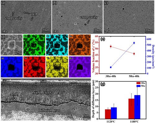
Figures (f) show the oxide layer structure. It consists of the NiO, Ni(Al, Cr)2O4 and Al2O3 oxide layers and the diffusion layer in the metal. The oxide layers are easy to peel off, and the depth of the diffusion layer is positively correlated with the thickness of the oxide scale [Citation22,Citation23]. Therefore, the depth of the diffusion layer is used to investigate the difference in oxidation degree, as shown in Figure (g). The diffusion layer is found to increase with temperature and the addition of Ru. This is similar to the observations in the literature [Citation24,Citation25], the addition of Ru leads to accelerated oxidation of the alloy. However, the deviation caused by adding Ru is less than ∼ 5 μm at any temperature. Considering the thickness of the oxide layer is twice the diffusion layer, the deviation can estimate to be ∼10 μm. This is in the same magnitude as one creep cavity. In this regard, the difference in creep life caused by oxidation is far less than that caused by creep cavities.
Dislocation network spacing is also generally considered to influence the creep lives of Nickel-based single-crystal alloys [Citation26,Citation27]. Figure shows a TEM examination of the dislocation networks in the four creep samples. All four samples exhibit dislocation networks containing <110> and <100> dislocations, as evident in Figures (a) ∼ (d). Figures (e) ∼ (h) show the size distributions of dislocation cells. They are all similar at ∼ 30 nm. Figure (i) shows the EDS element mapping around a dislocation in the 3Ru alloy after the creep test at 1120 °C/100 MPa. Table presents the quantitative chemical analysis of the dislocation and its surrounding γ matrix. The dislocation line is rich in Co, Cr and Re, poor in Al and Ni, and neutral for Ta and Ru. In addition, the 5Ru alloy appears to have lower partition ratios for the Co, Cr and Re elements between the dislocation and the matrix.
Figure 4. Morphologies of dislocation networks and element distributions around dislocations. (a) ∼ (d) The morphologies of dislocation networks; (e) ∼ (h) size distributions of the dislocation cell; (i) EDS element mapping around a dislocation in the 3Ru alloy after the creep test at 1120 °C/100 MPa.
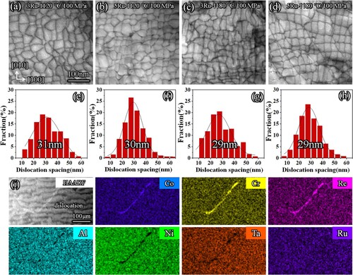
Table 2. Chemical composition measurement of matrix and dislocation (wt. %).
The 5Ru alloy showed a longer creep life than the 3Ru alloy at 1120 °C/100 MPa but a lower creep life at 1180 °C/100 MPa. This is attributed to two reasons. First, no TCP phases is formed in the 5Ru alloy at both temperatures. This is attributed to the effect of Ru in reducing the volume fraction of the γ′ phase. A higher volume fraction of the γ phase can accommodate (or dilute) more TCP phases forming elements, thus suppressing its formation. This is consistent with the lower partition ratios for the Co, Cr and Re between the dislocation and the matrix in the 5Ru alloy. The formation of TCP phase needle precipitates decreases the creep life by causing local stress concentrations and internal cracking. This explains the longer creep life of the 5Ru alloy at 1120 °C/100 MPa. At 1180 °C, the advantage of 5Ru alloy in inhibiting the precipitation of the TCP phases decreases as the dissociation of the γ′ phase is enhanced. This is also the reason why there are fewer TCP phases precipitates in the 3Ru alloy at 1180 °C/100 MPa than at 1120 °C/100 MPa. Second, a lower volume fraction of the γ′ phase in the 5Ru alloy makes it exhibit a higher strain as the plasticity of γ′ phase is lower than the γ phase [Citation28,Citation29]. This leads to a higher density of creep cavities formed in the 5Ru alloy. The creep cavities cause local stress concentrations and promote internal cracking. This contributes to the lower creep life of the 5Ru alloy at 1180 °C/100 MPa.
After excluding the influence of oxidation. This study suggests that the creep mechanism of the alloy is still consistent with the conventional dislocation motion and diffusion mechanisms [Citation30,Citation31]. For example, under creep conditions of 1180 °C/100 MPa, the dislocation movement and diffusion of the alloy intensify. At this point, the creep life of the alloy will be significantly reduced. However, this study observed that the dislocation network spacing remained basically unchanged for different Ru contents. Therefore, the movement and morphology of dislocations are not the main reasons for the differences in creep performance at the same temperature. Furthermore, during creep, both the TCP phase and creep cavities originate from diffusion behavior. Therefore, the TCP phase and creep cavities are weak links in the alloy during service.
4. Conclusion
The creep life of the 5Ru alloy is longer than that of the 3Ru alloy at 1120 °C/100 MPa. This is attributed to the effect of Ru in preventing the formation of the TCP phases. The creep life of the 5Ru alloy is shorter than that of the 3Ru alloy at 1180 °C/100 MPa. This is mainly attributed to the higher density of the creep cavity. They are both caused by decreased volume fraction of γ′ phase with temperature. The difference in creep life caused by oxidation is far less than that caused by creep cavities as the dimension only match the magnitude of one creep cavity.
Disclosure statement
No potential conflict of interest was reported by the author(s).
Additional information
Funding
References
- Han L, Li P, Yu S, et al. Creep/fatigue accelerated failure of Ni-based superalloy turbine blade: microscopic characteristics and void migration mechanism. Int J Fatigue. 2022;154:106558.
- Williams JC, Starke EA. Progress in structural materials for aerospace systems11 the golden jubilee issue—selected topics in materials science and engineering: past, present and future, edited by S. Suresh. Acta Mater. 2003;51(19):5775–5799.
- Caron P, Khan T. Evolution of Ni-based superalloys for single crystal gas turbine blade applications. Aerosp Sci Technol. 1999;3(8):513–523.
- Singer R. Advanced materials and processes for land-based gas turbines. Proc Mater Adv Power Eng. 1994: 1707–1729.
- Reed RC. The superalloys fundamentals and applications. Cambridge: Cambridge University; 2006.
- Gaag T, Ritter N, Peters A, et al. Improving the effectiveness of the solid-solution-strengthening elements Mo, Re, Ru and W in single-crystalline nickel-based superalloys. Metals. 2021;11(11):1707.
- Wang Y, Zhao M, Li Z, et al. The synergistic effect of Re and W on the evolution of TCP phases in nickel-based superalloys. J Alloys Compd. 2022;900:163286.
- Guoqi Z, Sugui T, Delong S, et al. Influence of Ru on creep behaviour and concentration distribution of Re-containing Ni-based single crystal superalloy at high temperature. Mater Res Express. 2020;7(6):066507.
- Sato A, Harada H, Yokokawa T, et al. The effects of ruthenium on the phase stability of fourth generation Ni-base single crystal superalloys. Scr Mater. 2006;54(9):1679–1684.
- Belan J. GCP and TCP phases presented in Nickel-base superalloys. Mater Today Proc. 2016;3(4):936–941.
- Zhang Z, Yue Z. TCP phases growth and crack initiation and propagation in nickel-based single crystal superalloys containing Re. J Alloys Compd. 2018;746:84–92.
- Heckl A, Neumeier S, Cenanovic S, et al. Reasons for the enhanced phase stability of Ru-containing nickel-based superalloys. Acta Mater. 2011;59(17):6563–6573.
- Yeh AC, Tin S. Effects of Ru and Re additions on the high temperature flow stresses of Ni-base single crystal superalloys. Scr Mater. 2005;52(6):519–524.
- Peng Z, Povstugar I, Matuszewski K, et al. Effects of Ru on elemental partitioning and precipitation of topologically close-packed phases in Ni-based superalloys. Scr Mater. 2015;101:44–47.
- Singer RRaRF. Influence of ruthenium on topologically close packed phase precipitation in single-crystal ni-based superalloys: numerical experiments and validation. Superalloys. 2012;2012:205–214.
- El-Bagoury N. Ni base superalloy: casting technology, metallurgy, development, properties and applications. Int J Eng Sci Res Technol. 2016;5(2):108–152.
- Zhao Y, Luo Y, Zhang M, et al. On the effect of Ru upon creep behaviour and dislocation evolution in Ni-based single crystal superalloys. Mater Today Commun. 2022;30:103220.
- Song W, Wang XG, Li JG, et al. Effect of ruthenium on microstructure and high-temperature creep properties of fourth generation Ni-based single-crystal superalloys. Mater Sci Eng A. 2020;772:138646.
- Wang T, Wang X, Zhao Z, et al. Dissolution behaviour of the γ′ precipitates in two kinds of Ni-based superalloys. Mater High Temp. 2016;33(1):51–57.
- Kawagishi K, Harada H, Sato A, et al. The oxidation properties of fourth generation single-crystal nickel-based superalloys. JOM. 2006;58(1):43–46.
- Kawagishi K, Sato A, Sato A, et al. Oxidation behavior of Ru-containing Ni-base single-crystal superalloys. Mater Sci Forum. 2006;522-523:317–322.
- Hu Y, Cao T, Cheng C, et al. Oxidation behavior of a single-crystal Ni-based superalloy over the temperature range of 850 °C–950 °C in air. Appl Surf Sci. 2019;484:209–218.
- Hu Y, Cheng C, Zhang L, et al. Microstructural evolution of oxidation film on a single crystal nickel-based superalloy at 980 °C. Oxid Met. 2018;89(3):303–317.
- Sun J, Liu J, Li J, et al. Dual effects of Ru on the microstructural stability of a single crystal superalloy. Scr Mater. 2021;205:114209.
- Edmonds IM, Evans HE, Jones CN, et al. The kinetics of oxidation of Ru-bearing nickel-based superalloys. Mater Sci Forum. 2008;595:59–67.
- Zhang J, Murakumo T, Koizumi Y, et al. Interfacial dislocation networks strengthening a fourth-generation single-crystal TMS-138 superalloy. Metall Mat Trans A. 2002;33(12):3741–3746.
- Zhang J, Murakumo T, Harada H, et al. Creep deformation mechanisms in some modern single-crystal superalloys. Superalloys. 2004;2004:189–195.
- McHugh RMPE. Modelling of creep in a Ni base superalloy using a single crystal plasticity model. Comput Mater Sci. 1997;9:134–140.
- Zhang Y, Yang C, Xu Q. Numerical simulation of microstructure evolution in Ni-based superalloys during P-type rafting using multiphase-field model and crystal plasticity. Comput Mater Sci. 2020;172:109331.
- Jogi T, Bhattacharya S. Interfacial dislocation network in precipitation strengthened alloys during creep: a discrete dislocation dynamics (DDD) study in three dimensions. Modell Simul Mater Sci Eng. 2021;29(3):035010.
- Sugui T, Huihua Z, Jinghua Z, et al. Formation and role of dislocation networks during high temperature creep of a single crystal nickel–base superalloy. Mater Sci Eng A. 2000;279(1):160–165.