
Abstract
The deformation of a single-crystal Fe48Mn32Co10Cr10 alloy is captured in situ at the atomic scale. The results show that full and partial dislocations, along with deformation twins, are involved in the deformation process. Partial dislocation activities result in the formation of nanotwins, high-density coherent twin boundaries, and incoherent twin boundaries. Full dislocations interact with the coherent/incoherent twin boundaries, and partial dislocations, thereby producing high strength and remarkable strain hardening. The observed high activity of full dislocations can be attributed to the inhomogeneous distribution of solid solution atoms in the alloy.
GRAPHICAL ABSTRACT
Introduction
Recently, there has been a global surge in interest in high-entropy alloys (HEA) owing to their outstanding mechanical properties [Citation1–6]. Among these alloys, FeMnCoCr is of particular interest owing to its high ductility and remarkable strain-hardening [Citation7–10]. The mechanical properties of the materials are directly related to their deformation mechanisms. Understanding deformation mechanisms is essential to facilitate the design of tailored HEAs with exceptional mechanical properties. Therefore, numerous studies have investigated the deformation mechanisms of FeMnCoCr alloys. Many interesting ex situ studies and nanoscale resolution investigations have suggested that the plastic deformation of FeMnCoCr alloys is governed by partial dislocations [Citation11–13]. For example, Li et al. [Citation14] showed that partial dislocation results in a phase transition from a face-centered cubic (FCC) to a hexagonal close-packed (HCP) structure and that deformation twinning occurs in the Fe50Mn30Co10Cr10 alloy after plastic deformation. Many researchers have concluded that FeMnCoCr alloys have low stacking fault energies and that partial dislocation and deformation twinning are known to frequently nucleate, whereas full dislocation activity during deformation is rare. However, most previous studies were performed at a nanoscale resolution and were therefore unable to clearly distinguish between full and partial dislocations. It is unclear whether full dislocation occurs during deformation, owing to the lack of direct atomic-scale evidence. Moreover, deformation twins not only provide plasticity but also interact with mobile dislocations, resulting in strong strain hardening [Citation15–17]. Picak et al. [Citation18] suggested that the deformation of Fe40Mn40Co10Cr10 alloy was governed by partial dislocations, which led to the formation of high-density nanotwins. Further deformation increases the prevalence of twin-twin and twin-dislocation interactions, leading to strong strain hardening in these systems. Without in-situ atomic-scale observations, the mechanism by which these deformation twins cause strain-hardening remains unclear owing to a lack of in-situ atomic-scale observations; therefore, such in-situ atomic-scale results are required to elucidate the deformation mechanism of FeMnCoCr alloys.
In this study, the deformation behavior of an Fe48Mn32Co10Cr10 single-crystal nanoplate was observed in situ using transmission electron microscopy (TEM) with a tensile device. We provide a direct in-situ observation of the atomic-scale deformation behavior of an Fe48Mn32Co10Cr10 high-entropy alloy. Full and partial dislocations along with deformation twins are involved in the deformation process. In addition, partial dislocation activities led to the formation of high-density nanotwins, after which full dislocations interacted with the coherent twin boundary (CTB), incoherent twin boundary (ITB), and partial dislocations, thereby increasing the strain hardening.
Method
The Fe48Mn32Co10Cr10 single-crystal nanoplate was derived from an annealed polycrystalline bulk Fe48Mn32Co10Cr10 alloy with an FCC structure. Our results reveal that the annealed bulk alloy has an average grain size of approximately 3 μm, and importantly, there is no HCP phase present in this alloy (further details can be found in the Supplementary Materials under Method S1). Fig. S1 presents the stress–strain curve of the annealed polycrystalline bulk Fe48Mn32Co10Cr10 alloy. Prior to further examination, the alloy was initially characterized using electron backscatter diffraction (EBSD). Subsequently, using the orientation distribution derived from the inverse pole figure via EBSD, a tensile sample was extracted from grains aligned with the [110] zone axes. This extraction was performed using a Helios G4 UC focused ion beam (FIB). The nanoplate tensile sample was cut into the shape of a dog bone with a length, width, and thickness of 1000, 400, and 100 nm, respectively (more details in Method S1). The nanoplate was then attached to an INSTEMS-MT in situ tensile device with double-tilt capability [Citation19,Citation20] and observed using an FEI Titan environmental transmission electron microscope (TEM). The EBSD characterization was performed using an FEI-Quanta 650 field-emission scanning electron microscope equipped with an EBSD system from TexSEM Laboratories.
Results and discussion
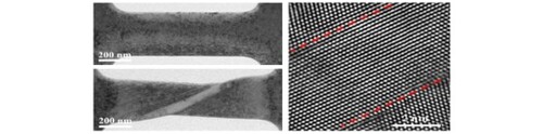
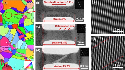
Figure a shows the EBSD pattern of the polycrystalline Fe48Mn32Co10Cr10 alloy used for fabricating the single-crystal nanoplate for the in situ tensile test. A single-crystal sample for in-situ tensile testing was fabricated from grains with a [110] zone axis identified in the EBSD image. The TEM image captured before deformation (Figure b), in which the viewing direction was along the [110] zone axis, showed that the tensile sample contained no grain boundaries or growth twins. The selected area electron diffraction (SAED) pattern of the nanoplate (Figure b, inset) shows typical single-crystalline features, which can be well indexed to the FCC-structured Fe48Mn32Co10Cr10 alloy. Several nanoscale deformation twins with thicknesses ranging from 1 to 10 nm were formed as the strain increased to 5.8% during tensile processing (red arrows in Figure c). These deformation twins resulted from partial dislocations, and passed through the entire tensile sample. With further loading, both the number and thickness of the deformation twins increased (Figure d). The increase of thickness of these deformation twins was also attributed to the typical layer-by-layer gliding of partial dislocations, which is consistent with the results of previous studies on FeMnCoCr alloys [Citation11–17]. As the strain increased, many twinned spots appeared in the SAED patterns (Figure c and 1d, insets), further confirming the generation of deformation twins. The single-crystalline features of the nanoplate before deformation are clearly observed in the high-resolution TEM (HRTEM) image (Figure e). The HRTEM image captured after plastic deformation shows that deformation twins were generated (Figure f). Furthermore, no HCP phase is generated during the loading of nanoplate.
Figure 1. (a) EBSD characterization of Fe48Mn32Co10Cr10 alloy. (b) Nanoplate fabricated from a grain of the alloy using FIB. (c) Nanoscale deformation twins generated during straining. (d) The number and thickness of the deformation twins increased with strain. The insets in parts b-d show the corresponding SAED pattern of the deformed region. (e, f) HRTEM images captured before and after plastic deformation.
In addition to the formation of nanoscale deformation twins, full dislocation and deformation-twin interactions were directly observed. Figure shows a typical example of in situ atomic-scale HRTEM images of the twin-dislocation interaction during straining. The CTB and reference area for the in situ observations are indicated by red dashed lines and orange dashed rectangles, respectively. A deformation twin approximately 5 nm in thickness was observed (Figure a), along with many full dislocations pinned on the top side of the CTB (indicated by the symbol ‘T’). As observed, there is an additional (111) plane inserted on the CTB (detailed in Figure e), indicative of a typical full dislocation structure with a Burgers vector of 1/2<110> and a glide plane of (111) [Citation21]. Moreover, numerous atomic-scale steps are evident on the CTB. These steps emerge due to the emission and glide of partial dislocations on the CTB. When these partial dislocations stop at the CTB, they lead to the formation of steps. Therefore, in this study, these types of steps on the CTB directly correspond to partial dislocations. These partial dislocations possess a Burgers vector of 1/6<112> and a glide plane of (111) [Citation22,Citation23], and notably, they do not introduce additional (111) planes (as seen in Figure f). Full dislocations often hinder the glide of partial dislocations on the CTB. Therefore, many atomic-scale steps are pinned on the CTB. The bottom of this deformation twin varies in thickness, with that of the left-side and right-side twins being ∼ 4.4 nm and ∼ 5.5 nm in thickness, respectively, owing to a step with 7 atomic layers. This large step represents an ITB [Citation24–26], and several full dislocations are pinned in this region. With increasing strain, as shown in Figure b-d, many full dislocations escaped from the CTB, whereas many new full dislocations were simultaneously pinned onto the CTB. These pinning and unpinning processes frequently occur in the CTB during deformation.
Figure 2. (a-d) In-situ HRTEM images of full dislocation interactions with the CTB and ITB in the Fe48Mn32Co10Cr10 alloy. The CTB is indicated by the red dashed line, and ITB is indicated by the dashed rectangle. Full dislocations are marked with symbol ‘T’.
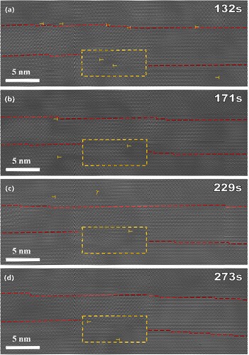
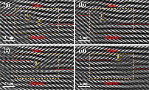
Figure 3. (a-d) Magnified HRTEM images showing the full dislocation-CTB interaction during deformation. (e, f) HRTEM extract from the framed region of (b, c).
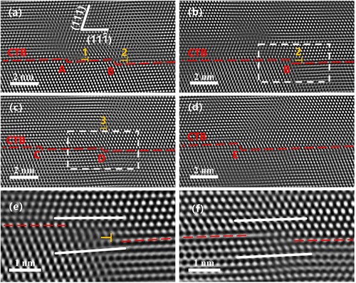
In the initial stages of deformation, the successive emission of partial dislocations on {111} plane resulted in twin nucleation. Subsequently, numerous partial dislocations glided along the CTB, generating atomic-scale steps. As the loading progressed, many gliding partial dislocations were obstructed by full dislocations, resulting in the formation of complex steps due to the interaction of full dislocations with the steps. Figure presents a series of magnified HRTEM images that demonstrate the interactions between the full dislocations and the CTB during deformation. Two full dislocations (denoted ‘1’ and ‘2’ in Figure a) are pinned by the CTB (as shown in Figure e, there is an extra (111) plane insert on the CTB), leading to localized distortions in the lattice. This type of dislocation-CTB interaction increases the stress of dislocation sliding, leading to strain-hardening [Citation27,Citation28]. In addition, several steps (denoted ‘A’ and ‘B’ in Figure ) are formed on the CTB at the location of full dislocation. These complex steps result from the interaction of partial dislocations on the CTB and full dislocations with the (111) glide plane. Our in-situ atomic-scale observations show that the movement of these types of complex steps is severely inhibited until the full dislocation escapes from the CTB. Thus, the motion of these step types typically requires a relatively long time. As the strain increases (Figure b), the full dislocation ‘1’ escapes from the observed area, and the step resulting from this partial dislocation quickly glides right to left, causing step ‘A’ to disappear. In contrast, step ‘B’ shows no obvious change because the full dislocation ‘2’ remains pinned. This observation further confirmed that the full dislocation-CTB interaction obstructed partial dislocations in the CTB and inhibited CTB migration. As the strain is further increased (Figure c), the full dislocation ‘2’ escapes from the CTB, resulting in the rapid disappearance of step ‘B’ owing to the removal of the obstruction caused by the full dislocation. Meanwhile, two new steps of one atomic layer (denoted ‘C’ and ‘D’) and full dislocation ‘3’ were generated. The rapid gliding of partial dislocations on the CTB lead to the formation of steps ‘C’ and ‘D’ (Figure d), which combine to form the two-atomic-layers thick step ‘E.’ The results presented above indicate that deformation-induced nanotwins not only anchor the full dislocation but also hinder the movement of partial dislocations on the CTB, resulting in enhanced strain hardening. (Two additional examples show full dislocations resting on the CTB and blocking partial dislocations, leading to the formation of complex steps). Figure e provides a magnified HRTEM image, clearly displaying both the full dislocation and a step on the CTB (related to Figure b). Figure f offers a zoomed-in HRTEM image that corresponds to the highlighted region in Figure c, illustrating solely the step on the CTB.
Figure displays a series of enlarged HRTEM images showing the full dislocation-ITB interaction during deformation. In the region enclosed by the orange dashed rectangle, the CTB on the left is seven atomic layers higher than that on the right, forming a typical ITB consisting of seven atomic layers between the matrix and the deformation twin. In situ observations revealed that the ITB also inhibited the movement of full dislocations. In Figure a, two full dislocations (labeled ‘1’ and ‘2’) are anchored on the ITB's left side, revealing an additional (111) plane embedded within the ITB. This structure contrasts with the ITB devoid of a full dislocation, as illustrated in Fig. S2. The ITB is formed by a sequence of partial dislocations with a glide plane parallel to the CTB, and its migration is driven by the movement of these partial dislocations [Citation29,Citation30]. When the full dislocation on the (111) glide plane interacts with the ITB, a high stress is necessary to activate the motion of the partial dislocation array (comprising the ITB), contributing to strain hardening. Our in-situ atomic-scale observations showed that the interaction of the ITB with the full dislocation strongly inhibits its movement until the full dislocation escapes. With increasing strain, the full dislocations ‘1’ and ‘2’ escaped from the observed area (Figure b and 4c). Simultaneously, a new full dislocation labeled as ‘3’ emerges and also interacts with the ITB (see Figure c). As the strain continues to increase, similar interactions between the full dislocation and ITB, and the escape of the full dislocation from the ITB, are observed once more (Figure d). Furthermore, comparing Figure a-4d reveals shifts in the position and structure of the ITB, suggesting that the partial dislocation array motion was active during the straining process [Citation29,Citation30]. Typically, ITB migration takes place when the full dislocation disengages from the ITB, indicating full dislocation-ITB interaction inhibits the ITB movement. Based on images taken during in-situ experiments, we plotted the ITB migration distance against time (refer to Fig. S4 in Supplementary Materials). The results demonstrate that the ITB migration rate drops when full dislocations are anchored to the ITB. Conversely, when these dislocations depart from the ITB, the migration rate of the ITB elevates, further confirming that the full dislocation-ITB interaction inhibits the ITB motion. While ITBs have pinned full dislocations, these dislocations might also impede ITB migration, contributing to pronounced strain hardening. Here, we primarily center on the movement of the ITB, which consists of an array of partial dislocations. It is worth noting, however, that in other regions, numerous partial dislocations glide on the CTB. This is validated by the observed migration of the CTB and the progression of multiple steps on the CTB during loading.
Figure 4. (a-d) Magnified HRTEM images showing the full dislocation-ITB interaction during deformation.
Many previous studies attributed the excellent mechanical properties of FeMnCoCr alloys to partial dislocations, FCC to HCP phase transitions, and deformation twinning [Citation11–17]. Our in-situ observations provide direct evidence that full and partial dislocations and deformation twins are involved in the deformation of Fe48Mn32Co10Cr10 nanoplates. First, partial dislocations result in the formation of many nanotwins, leading to high CTB and ITB densities in the nanoplate tensile sample. Second, both the CTB and ITB strongly inhibited the motion of dislocations and played important roles in strain hardening. The frequent activity of full dislocations may be a consequence of the inhomogeneous distribution of solid-solution atoms, which leads to variations in the chemical composition at different locations in HEA [Citation31–34]. This variation in chemical composition leads to variations in mechanical properties owing to changes in local stacking fault energy (SFE) [Citation35–37]. Partial dislocations and nanotwins are preferred in regions with low SFE, whereas full dislocation activities frequently occur in regions with relatively high SFE. Therefore, the plastic deformation of the Fe48Mn32Co10Cr10 alloy is governed by both full and partial dislocations.
The deformation mechanism observed in the single-crystal nanoplate is also anticipated to be present in bulk polycrystalline alloys. However, considering the extensive presence of grain boundaries in the latter, it is important to be circumspect when applying our findings to bulk polycrystalline alloys. This distinction becomes evident when comparing the stress–strain curves of a single-crystal nanoplate to those of the bulk polycrystalline Fe48Mn32Co10Cr10 alloy (refer to Fig. S1 and S5). While both curves display clear strain hardening, the single-crystal nanoplate shows higher stress but limited ductility. In contrast, the bulk polycrystalline Fe48Mn32Co10Cr10 alloy exhibits larger plasticity but low strength. In bulk polycrystalline alloys, both pre-existing dislocations and grain boundaries can act as sources of dislocations, thereby enhancing plasticity [Citation38–41]. Furthermore, as noted in our earlier study [Citation10], the HCP phase also generates during deformation. Consequently, there is an expectation of a high density of deformation twins, both partial and full dislocations, and the HCP phase within the grains. The emergence of these diverse defects and their subsequent interactions contribute to the bulk polycrystalline Fe48Mn32Co10Cr10 alloy's pronounced plasticity and strain hardening. On the other hand, the single-crystal nanoplate, due to its reduced initial dislocation density and smaller size, necessitates higher stress for dislocation nucleation owing to size effects [Citation42,Citation43]. Moreover, dislocations in the nanoplate are easily escaped. As a result, strain hardening primarily stems from the interactions of full dislocations with CTB and ITB after the generation of deformation nanotwins. This leads to the nanoplate displaying high strength, albeit with limited ductility.
Conclusion
In summary, our in-situ atomic-scale observations reveal that, in addition to partial dislocations, full dislocations also significantly influence the plastic deformation of the single-crystal Fe48Mn32Co10Cr10 alloy. Initial partial dislocation activity prompts the formation of deformation nanotwins, resulting in a high density of CTB and ITB, which in turn enhance plasticity. As strain intensifies, full dislocations interact with CTB and ITB introducing two types of strain-hardening. This provides insight into the strain-hardening observed in the Fe48Mn32Co10Cr10 alloy. Moreover, full dislocations on CTB hinder the gliding of partial dislocations on the CTB, which causes the emergence of complex step formations. These findings are expected to deepen our understanding of the deformation mechanisms in HEAs and guide the development of HEAs with optimized mechanical properties
Supplemental Material
Download ()Disclosure statement
No potential conflict of interest was reported by the author(s).
Additional information
Funding
References
- George EP, Raabe D, Ritchie RO. High-entropy alloys. Nat Rev Mater. 2019;4(8):515–534. doi:10.1038/s41578-019-0121-4
- Miracle DB, Senkov ON. A critical review of high entropy alloys and related concepts. Acta Mater. 2017;122:448–511. doi:10.1016/j.actamat.2016.08.081
- Li Z, Zhao S, Ritchie RO, et al. Mechanical properties of high-entropy alloys with emphasis on face-centered cubic alloys. Prog Mater Sci. 2019;102:296–345. doi:10.1016/j.pmatsci.2018.12.003
- Zhang Y, Zuo TT, Tang Z, et al. Microstructures and properties of high-entropy alloys. Prog Mater Sci. 2014;61:1–93. doi:10.1016/j.pmatsci.2013.10.001
- George EP, Curtin WA, Tasan CC. High entropy alloys: a focused review of mechanical properties and deformation mechanisms. Acta Mater. 2020;188:435–474. doi:10.1016/j.actamat.2019.12.015
- Park JM, Yang DC, Kim HJ, et al. Ultra-strong and strain-hardenable ultrafine-grained medium-entropy alloy via enhanced grain-boundary strengthening. Mater Res Lett. 2021;9(7):315–321. doi:10.1080/21663831.2021.1913768
- He ZF, Jia N, Wang HW, et al. The effect of strain rate on mechanical properties and microstructure of a metastable FeMnCoCr high entropy alloy. Mater Sci Eng, A. 2020;776:138982. doi:10.1016/j.msea.2020.138982
- He ZF, Jia N, Ma D, et al. Joint contribution of transformation and twinning to the high strength-ductility combination of a FeMnCoCr high entropy alloy at cryogenic temperatures. Mater Sci Eng, A. 2019;759:437–447. doi:10.1016/j.msea.2019.05.057
- Su J, Raabe D, Li Z. Hierarchical microstructure design to tune the mechanical behavior of an interstitial TRIP-TWIP high-entropy alloy. Acta Mater. 2019;163:40–54. doi:10.1016/j.actamat.2018.10.017
- Xu N, Yang Z, Mu X, et al. Effect of Al addition on the microstructures and deformation behaviors of non-equiatomic FeMnCoCr metastable high entropy alloys. Appl Phys Lett. 2021;119(26):261902. doi:10.1063/5.0069518
- Qi L, Huang XD, Zhang AP, et al. Martensitic transformation induced dislocation walls in Fe42Mn38Co10Cr10 high-entropy alloy. Scr Mater. 2021;201:113929. doi:10.1016/j.scriptamat.2021.113929
- Niu P, Li R, Fan Z, et al. Additive manufacturing of TRIP-assisted dual-phases Fe50Mn30Co10Cr10 high-entropy alloy: microstructure evolution, mechanical properties and deformation mechanisms. Mater Sci Eng, A. 2021;814:141264. doi:10.1016/j.msea.2021.141264
- Wei S, Kim J, Tasan CC. Boundary micro-cracking in metastable Fe45Mn35Co10Cr10 high-entropy alloys. Acta Mater. 2019;168:76–86. doi:10.1016/j.actamat.2019.01.036
- Li Z, Pradeep KG, Deng Y, et al. Metastable high-entropy dual-phase alloys overcome the strength-ductility trade-off. Nature. 2016;534(7606):227–230. doi:10.1038/nature17981
- Deng Y, Tasan CC, Pradeep KG, et al. Design of a twinning-induced plasticity high entropy alloy. Acta Mater. 2015;94:124–133. doi:10.1016/j.actamat.2015.04.014
- Yang S, Yang Y. Thermodynamics-kinetics of twinning/martensitic transformation in Fe50Mn30Co10Cr10 high-entropy alloy during adiabatic shearing. Scr Mater. 2020;181:115–120. doi:10.1016/j.scriptamat.2020.02.024
- Li S, Li L, Souami A, et al. In-situ observation of deformation twin associated sub-grain boundary formation in copper single crystal under bending. Mater Res Lett. 2022;10(7):488–495. doi:10.1080/21663831.2022.2057201
- Picak S, Liu J, Hayrettin C, et al. Anomalous work hardening behavior of Fe40Mn40Cr10Co10 high entropy alloy single crystals deformed by twinning and slip. Acta Mater. 2019;181:555–569. doi:10.1016/j.actamat.2019.09.048
- Wang L, Zhang Y, Zeng Z, et al. Tracking the sliding of grain boundaries at the atomic scale. Science. 2022;375(6586):1261–1265. doi:10.1126/science.abm2612
- Zhang Z, Mao MM, Wang J, et al. Nanoscale origins of the damage tolerance of the high-entropy alloy CrMnFeCoNi. Nat Commun. 2015;6(1):10143. doi:10.1038/ncomms10143
- Hirth JP, Lothe J, Mura T. Theory of dislocations (2nd ed.). J Appl Mech. 1983;50(2):476–477.
- Arzaghi M, Beausir B, Tóth LS. Contribution of non-octahedral slip to texture evolution of fcc polycrystals in simple shear. Acta Mater. 2009;57(8):2440–2453. doi:10.1016/j.actamat.2009.01.041
- Zhu YT, Liao XZ, Wu XL. Deformation twinning in nanocrystalline materials. Prog Mater Sci. 2012;57(1):1–62. doi:10.1016/j.pmatsci.2011.05.001
- Guo Y, Wang Z, Zhang B, et al. Twin thickness and dislocation interactions affect the incoherent-twin boundary phase in face-centered cubic metals. Cell Rep Phys Sci. 2022;3(3):100736. doi:10.1016/j.xcrp.2021.100736
- Chen Z, Zheng Y, Löfler L, et al. Real-time atomic-resolution observation of coherent twin boundary migration in CrN. Acta Mater. 2021;208:116732. doi:10.1016/j.actamat.2021.116732
- Kou Z, Huang R, Yang Y, et al. Revealing the atomic-scale evolution of sessile disconnections on twin boundaries during deformation. Scr Mater. 2022;221:114956. doi:10.1016/j.scriptamat.2022.114956
- Zhu YT, Wu XL, Liao XZ, et al. Dislocation-twin interactions in nanocrystalline fcc metals. Acta Mater. 2011;59(2):812–821. doi:10.1016/j.actamat.2010.10.028
- Lu K, Lu L, Suresh S. Strengthening materials by engineering coherent internal boundaries at the nanoscale. Science. 2009;324(5925):349–352. doi:10.1126/science.1159610
- Arroyo Rojas Dasilva Y, Erni R, Isa F, et al. Atomic-scale structural characterization of grain boundaries in epitaxial Ge/Si microcrystals by HAADF-STEM. Acta Mater. 2019;167:159–166. doi:10.1016/j.actamat.2019.01.031
- Lu L, Chen X, Huang X, et al. Revealing the maximum strength in Nanotwinned copper. Science. 2009;323(5914):607–610. doi:10.1126/science.1167641
- Chen X, Wang Q, Cheng Z, et al. Direct observation of chemical short-range order in a medium-entropy alloy. Nature. 2021;592(7856):712–716. doi:10.1038/s41586-021-03428-z
- Ma E, Wu X. Tailoring heterogeneities in high-entropy alloys to promote strength-ductility synergy. Nat Commun. 2019;10(1):5623. doi:10.1038/s41467-019-13311-1
- Jian W, Xie Z, Xu S, et al. Effects of lattice distortion and chemical short-range order on the mechanisms of deformation in medium entropy alloy CoCrNi. Acta Mater. 2020;199:352–369. doi:10.1016/j.actamat.2020.08.044
- Chen X, Yuan F, Zhou H, et al. Structure motif of chemical short-range order in a medium-entropy alloy. Mater Res Lett. 2022;10(3):149–155. doi:10.1080/21663831.2022.2029607
- Wong SL, Madivala M, Prahl U, et al. A crystal plasticity model for twinning- and transformation-induced plasticity. Acta Mater. 2016;118:140–151. doi:10.1016/j.actamat.2016.07.032
- Laplanche G, Kostka A, Reinhart C, et al. Reasons for the superior mechanical properties of medium-entropy CrCoNi compared to high-entropy CrMnFeCoNi. Acta Mater. 2017;128:292–303. doi:10.1016/j.actamat.2017.02.036
- Uzer B, Picak S, Liu J, et al. On the mechanical response and microstructure evolution of NiCoCr single crystalline medium entropy alloys. Mater Res Lett. 2018;6(8):442–449. doi:10.1080/21663831.2018.1478331
- Shan Z, Stach EA, Wiezorek JMK, et al. Grain boundary-mediated plasticity in Nanocrystalline Nickel. Science. 2004;305(5684):654–657. doi:10.1126/science.1098741
- Zhou X, Li X, Lu K. Size dependence of grain boundary migration in metals under mechanical loading. Phys Rev Lett. 2019;122(12):126101. doi:10.1103/PhysRevLett.122.126101
- Cao P. The strongest size in gradient nanograined metals. Nano Lett. 2020;20(2):1440–1446. doi:10.1021/acs.nanolett.9b05202
- Li X, Sun S, Zou Y, et al. Twin-coupled shear bands in an ultrafine-grained CoCrFeMnNi high-entropy alloy deformed at 77 K. Mater Res Lett. 2022;10(6):385–391. doi:10.1080/21663831.2022.2053220
- Greer JR, Oliver WC, Nix WD. Size dependence of mechanical properties of gold at the micron scale in the absence of strain gradients. Acta Mater. 2005;53(6):1821–1830. doi:10.1016/j.actamat.2004.12.031
- Shan ZW, Mishra RK, Syed Asif SA, et al. Mechanical annealing and source-limited deformation in submicrometre-diameter Ni crystals. Nat Mater. 2008;7:115–119. doi:10.1038/nmat2085