
 ?Mathematical formulae have been encoded as MathML and are displayed in this HTML version using MathJax in order to improve their display. Uncheck the box to turn MathJax off. This feature requires Javascript. Click on a formula to zoom.
ABSTRACT
Surgical robots rely on robust and efficient computer vision algorithms to be able to intervene in real-time. The main problem, however, is that the training or testing of such algorithms, especially when using deep learning techniques, requires large endoscopic datasets which are challenging to obtain, since they require expensive hardware, ethical approvals, patient consent and access to hospitals. This paper presents VisionBlender, a solution to efficiently generate large and accurate endoscopic datasets for validating surgical vision algorithms. VisionBlender is a synthetic dataset generator that adds a user interface to Blender, allowing users to generate realistic video sequences with ground truth maps of depth, disparity, segmentation masks, surface normals, optical flow, object pose, and camera parameters. VisionBlender was built with special focus on robotic surgery, and examples of endoscopic data that can be generated using this tool are presented. Possible applications are also discussed, and here we present one of those applications where the generated data has been used to train and evaluate state-of-the-art 3D reconstruction algorithms. Being able to generate realistic endoscopic datasets efficiently, VisionBlender promises an exciting step forward in robotic surgery.
1. Introduction
Robotic surgery has revolutionised everyday surgical practice, and it has become a vital tool for many surgical procedures, enhancing surgical skills and allowing faster recovery for patients (Koh et al. Citation2018). Surgical robotic technologies constantly evolve with the ultimate goal to enable autonomous surgical task execution (Zhang et al. Citation2017a, Citation2017b; Zhan et al. Citation2020). For this purpose, a robot needs to be able to perceive the surgical scene in real-time and to precisely move surgical tools in reference to the deforming soft tissue. The standard approach for robotic scene perception is through computer vision algorithms, analysing in real-time image data captured by an endoscopic camera. However, the development and validation of surgical vision algorithms, both for traditional computer vision and for deep learning-based techniques, relies on having access to large datasets of endoscopic images and videos. Obtaining these datasets can be particularly challenging as it requires accessing expensive hardware, securing ethical approval, procuring patient consent and having regular access to hospitals. These obstacles result in a complex and time-consuming process, which contributes to delays for research and innovation in this field.
Currently, a few endoscopic datasets are publicly available, such as the Hamlyn Endoscopic Video Dataset (Giannarou et al. Citation2013) and the MICCAI Endoscopic Video Challenge (EndoVis Citation2015–2020). These datasets, while valuable, are still significantly limited in size and content. Generating synthetic datasets programmatically using realistic surgical scenes provides a solution to the challenges outlined above. This approach leverages recent advancements in computer graphics hardware and software to efficiently generate large and realistic datasets, with accurate ground truth data. Current synthetic dataset generators, such as UnrealCV (Qiu and Yuille Citation2016) and ML-ImageSynthesis (Zioma Citation2017), could potentially be used to generate endoscopic data. However, they lack the support to generate certain ground truth maps – for example, UnrealCV cannot generate optical flow – and they cannot also simulate playback of data as if authentically captured by a robot. This paper presents a solution to these challenges by introducing VisionBlender, a synthetic dataset generator that operates with Blender.Footnote1 Blender is increasingly becoming the premier solution for generating large training datasets (Veldhuizen Citation2018; Haim et al. Citation2018; Villegas et al. Citation2018; Newell and Densg Citation2020; Ranjan et al. Citation2020; Alexopoulos et al. Citation2020; Chen et al. Citation2020a, Citation2020b). To the best of our knowledge, VisionBlender is the first user interface to facilitate the generation of endoscopic training datasets within Blender. It offers a variety of unique features dedicated to surgical robotic vision, including a larger variety of ground truth maps.
VisionBlender supports the generation of both monocular and stereo video data, accompanied by ground truth maps of depth, disparity, segmentation masks, surface normals, optical flow, object pose and camera parameters (shown in ). Also, VisionBlender features the unique ability to generate ROS-compatible data – a process which accurately simulates data capture from a surgical robot. This process allows the user to play the simulation back at any desired frequency. VisionBlender will facilitate consistent comparison and benchmarking of computer vision algorithms for robotic surgery. Its simplicity and intuitive interface enables non-experts to use the solution and extended it to other computer vision applications, such as self-driving cars, human pose estimation, and robotics in general. It can also be used in computer vision courses to help students bridge the gap between theory and practice. In this paper, an example application for VisionBlender is presented. Specifically, VisionBlender has been used to generate a dataset of 23,000 endoscopic stereo images, to perform a comparison of state-of-the-art 3D reconstruction algorithms.
It is expected that VisionBlender will become the standard tool for generating computer vision datasets in Blender, providing high-quality data and covering the lack of existing solutions. The contributions of this paper are:
VisionBlender is introduced, the first user interface to generate ground truth data for computer vision applications in Blender;
Contrary to most of the existing generators, VisionBlender supports all the required ground truth maps for robotic surgery;
A ROS package is developed to support robotic applications and enable playback of the synthetic data as if a real surgical robot was capturing it;
Several different endoscopic virtual scenes were created in Blender which can be found along with VisionBlender’s code in our open-source repositoryFootnote2;
A ‘deep learning vs traditional computer vision’ analysis of state-of-the-art 3D reconstruction algorithms was performed, using generated synthetic data.
2. Methodology
2.1. Introducing VisionBlender
VisionBlender is a synthetic video and ground truth data generator for computer vision applications developed using Blender, a free and open-source computer graphics software. Blender was selected because of its recent surge in popularity with the computer vision community which can be primarily attributed to its Python API. Using the API the user can edit any part of the virtual scene (e.g., change the pose of a virtual object) through a Python script instead of manually clicking on the graphical user interface. Furthermore, Blender is an industry leader in generating realistic synthetic images. VisionBlender is an add-on that extends Blender’s functionality by adding the ability to generate ground truth maps of depth, disparity, segmentation masks, surface normals, optical flow, object pose, and camera parameters. , shows an example of the ground truth generated data on an endoscopic video sequence. Before rendering, the user can easily select which ground truth maps are to be generated, as shown on the user interface in .
Figure 1. VisionBlender’s user interface, displayed on the top right of the image
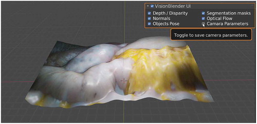
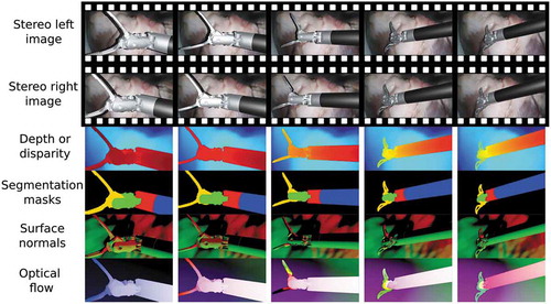
Figure 2. Example results of some generated ground truth maps in a video sequence of a robotic surgical instrument, moving over an ex vivo pig heart
A virtual scene is composed of virtual objects (e.g., tissue structure, surgical instruments), light sources, and a virtual camera. After creating the virtual scene, the user selects a render engine. In Blender 2.82 (VisionBlender’s initial release), two main render engines are available, namely Eevee and Cycles. In general, while Eevee was built for real-time rendering, Cycles was built for realism. Therefore, Cycles is significantly slower than Eevee at rendering images unless dedicated graphics cards (GPUs) are used. Currently, as shown in , while using Cycles, a user can generate all available types of ground truth maps, unlike Eevee, which cannot generate segmentation masks and optical flow ground truths.
Table 1. An overview of render engines in Blender 2.82, which can be used to generate different ground truth maps
Using VisionBlender, during each animation frame, Blender not only renders an image but also generates the ground truth maps relative to the virtual camera. At the end of rendering, one compressed zip file is created for each animation frame containing the ground truth maps. In the rest of this section, it is explained how each ground truth map is obtained.
2.1.1. Depth and disparity map
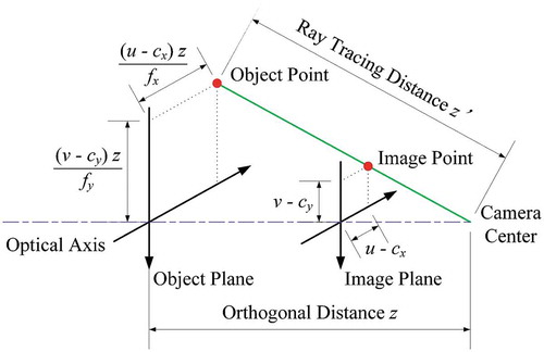
The depth is obtained from Blender’s Z pass. In Eevee, the output of the Z pass can be directly used as depth values, while in Cycles, EquationEq. (1)(1)
(1) needs to be applied first to the depth values. Since Cycles is a ray trace rendering engine, when using Cycles, the Z pass values correspond to the length of the ray from the object’s point to the camera’s pinhole (
). However, instead, the depth values should correspond to the orthogonal distance between the object’s point and the camera lenses plane (
), as shown in . For example, if a plane is in the virtual scene and is parallel to the camera lenses plane, all the points on the surface of that plane should have the same
value. Therefore, in Cycles, the following equation is applied:
where, and
are distances in
,
and
are the pixel coordinates of the point in the image,
and
the coordinates of the principal point in
, and
and
the focal lengths in
. Note that when the coordinates of the point in the image (
) coincide with the coordinates of the principal point(
), then
=
.
Figure 3. Projecting the ray tracing distance into the orthogonal distance
For stereo images, it is more convenient to generate disparity instead of depth maps. Therefore, when a virtual stereo camera is detected, the following equation is applied:
where is the disparity in
,
is the focal length in
,
is the baseline in
, and
is the depth in
. Since in Blender’s stereo cameras
then
.
2.1.2. Segmentation masks
To create segmentation masks in the presence of virtual objects, the user first assigns an integer index number for each virtual object. Then, using Blender’s Object Index pass, a mask can be extracted for each object. A single virtual object can have multiple masks associated with the different parts of that object, as shown in the surgical instruments depicted in . Conversely, the user could choose to use the same Object Index for multiple virtual objects so that they belong to the same class, for example, when training a semantic segmentation algorithm.
2.1.3. Surface normals and optical flow
The surface normals and optical flow ground truths are captured from Blender’s Normal, and Vector passes, respectively.
2.1.4. Object pose
By storing an object’s pose, its translation and rotation relative to the reference coordinate system of the virtual scene can be tracked. The translation is represented in Cartesian coordinates, and the orientation is represented with either quaternions or Euler angles. At each animation frame, an iteration through all the virtual objects stores the pose of each object’s coordinate system. It is possible to add multiple coordinate systems to a single object, to keep track of different parts of the object, which is particularly useful when tracking non-rigid objects such as soft tissue.
2.1.5. Camera parameters
The camera parameters are composed of the camera’s intrinsic and extrinsic parameter matrix. The intrinsic parameter matrix is calculated and stored once, before starting the rendering. Conversely, the extrinsic matrix is stored for every individual animation frame, since the virtual camera may move around the virtual scene between consecutive frames of an animation. The intrinsic matrix is represented by EquationEq. (3)(3)
(3) . These values are calculated, taking into account the focal length, sensor size, sensor fit, horizontal/vertical shift, and the rendered image resolution and pixel aspect ratio of Blender’s virtual camera. In Blender, there is no skew and no distortion on the rendered image.
The matrix (
) in EquationEq. (4
(4)
(4) ), represents the pose of the camera. A 3D point denoted by
in the virtual scene can be projected to a 2D point denoted by
in the rendered image using the following equation:
where s is an arbitrary scale factor.
2.2. Bringing the generated data into ROS
In the research field of robotic surgery, the Robot Operating System (ROS)Footnote3 middleware is extensively used to control robotic systems such as the da Vinci surgical robot, using the popular dVRK platform (Kazanzides et al. May 2014). When developing computer vision algorithms for surgical robots, it is advantageous to simulate that the data is being captured in real-time by an endoscopic camera to validate the algorithm, before testing on a real physical robot. Therefore, in VisionBlender, a ROS package is developed to convert the rendered images and ground truth data into ROS messages, which are then stored in a ‘rosbag’ file. The ‘rosbag’ file can be used to playback the rendered data at a chosen frequency as if that data was captured from a real camera sensor. With multiple ‘rosbag’ files, the computer vision software of the robot can be tested on multiple virtual scenarios.
2.3. VisionBlender in action
Figure 4. VisionBlender being used for training and validating an algorithm that estimates the pose of a surgical instrument using a cylindrical marker. This marker was taken from (Huang et al. Citation2020)
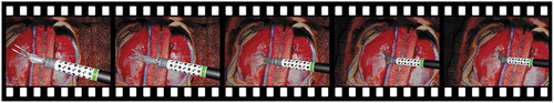
One of the primary applications for VisionBlender in robotic surgery is to generate datasets for training or validating surgical vision algorithms. For example, VisionBlender can be used for applications, such as surgical instrument pose estimation (as shown in ), instrument segmentation and tracking. This paper presents one of the possible applications as an example. Here, VisionBlender is used to generate endoscopic data to compare and evaluate 3D reconstruction algorithms.
2.3.1. Creating virtual scenes using a depth camera
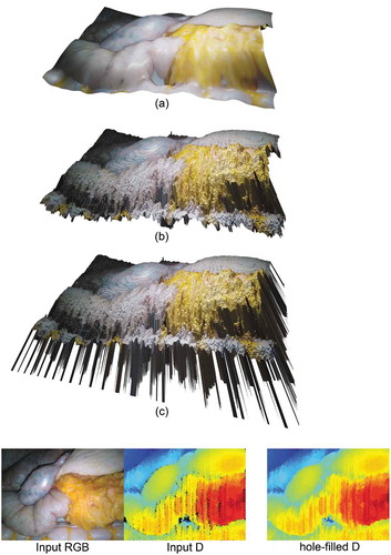
In this paper, the virtual scenes are created using the image and the 3D structure of a surgical scene (from ex vivo and phantom data) captured using a physical depth camera. Therefore, the generated video sequences look realistic by default. This advances the traditional approach for creating a virtual scene in Blender by 3D modelling the scene from scratch as, when using this traditional approach, how realistic or not the virtual scene looks depends heavily on the artist’s skills. Each virtual scene in VisionBlender has been created using the following process, which is illustrated in :
An RGB-D image is captured using a depth camera (e.g., Kinect camera);
The holes in the RGB-D image are filled using the approach of (Liu et al. Citation2016);
The RGB-D image with filled holes is converted into a Blender virtual object;
The virtual object is smoothed using Blender’s ‘CorrectiveSmooth’ function.
In total, 26 surgical scenes were created, displaying four phantoms and two ex-vivo organs. Examples of these virtual scenes can be found in our GitHub repository located at https://github.com/Cartucho/vision_blender. With 22 of these virtual scenes, 22,000 pairs of stereo images were generated (1,000 per each virtual scene) displaying two different abdominal phantoms. Those images were captured by moving the virtual camera through a pre-defined path in the virtual scene. Each pair of stereo images had a corresponding ground truth disparity map. This dataset was used for training deep learning algorithms in our performance evaluation study. The remaining four virtual scenes were used to generate a test set of 1,000 pairs of stereo images (250 per each virtual scene) to compare and evaluate all the selected 3D reconstruction algorithms in Section 3. Note that the stereo images produced with Blender were already horizontally aligned, so there was no need to rectify the images. All the generated images had a resolution of 256512 and the input RGB-D images, from the Kinect camera, had a resolution of 640
480.
Figure 5. Example of a virtual scene – created after processing an input RGB-D image – illustrating a liver-stomach phantom. (c) shows the obtained virtual scene before any processing – for illustration purposes, the depth values of the holes were set to a large constant value, resulting in the visible ‘spikes’. (b) shows the virtual scene after filling 7,784 holes using (Liu et al. Citation2016), and (a), shows the resulting virtual scene after smoothing the tissue using Blender’s ‘CorrectiveSmooth‘ object modifier. Using (a) a user can generate an endoscopic dataset
2.3.2. Deep learning
Using the training dataset described above (21,000 images for training, and 1,000 for validating), the state-of-art supervised learning algorithm proposed in (Chang and Chen Citation2018) and the unsupervised learning algorithm proposed in (Godard et al. Citation2017) were trained for 3D reconstruction. Both supervised and unsupervised algorithms used stereo image pairs as input to predict disparity maps as output. The algorithms were trained and tested in PyTorch.Footnote4
The selected supervised 3D reconstruction algorithm (Chang and Chen Citation2018) is one of the latest available and features an end-to-end estimation of disparity maps. It requires no additional post-processing and advances on previous methods in the literature by introducing pyramid stereo matching networks – an architecture that allows multi-scale context understanding. For unsupervised 3D reconstruction approaches, the neural network learns to regenerate the input stereo images, based on the warping of the input with the output predicted disparity map. (Godard et al. Citation2017) in particular introduces the foundation of unsupervised algorithms, where the left and right disparity maps are estimated by optimising for the image regeneration of the stereo pair. Though this unsupervised algorithm is introduced as monocular depth estimation, the authors also extend their framework to perform stereo matching to achieve better performance. The above algorithms were selected instead of more recent ones, such as (Pilzer et al. Citation2020), because of their code availability and their compatibility with our system.
2.3.3. Traditional computer vision
Despite the advances in deep learning algorithms for 3D reconstruction, traditional computer vision approaches are still extensively used in robotic surgery. A well-known algorithm is the Efficient Large-scale Stereo Matching (ELAS) (Geiger et al. Citation2011), which is used in our comparative study in this paper. The effectiveness of ELAS for surgical robot applications has been verified in multiple works (Zhang et al. Citation2017a, Citation2017b; Zhan et al. Citation2020; Lu et al. Citation2020). The main advantage when compared to the deep learning algorithms is that it does not need training, and it can be used off-the-shelf on a pair of rectified stereo images to estimate disparity.
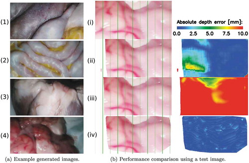
Figure 6. (a) Sample frames of our generated datasets including (1)-(2) training data from two different abdominal phantoms and testing data from an (3) ex vivo pig heart, and (4) ex vivo sheep brain. (b) Comparison example of the 3D reconstruction algorithms. (iv) is the left image from the stereo pair on which the ELAS algorithm had its best performance. (ii)-(iv) show the left-stereo images regenerated by using the disparity maps estimated with the supervised, unsupervised and ELAS algorithms, respectively. A colour map of the depth error is shown for each of the compared algorithms on the last column
3. Results
The test set, generated as described in Section 2.3.1, has been used to compare the performance of the 3D reconstruction algorithms selected above. It includes images displaying ex vivo pig heart and sheep brain tissue, as well as, a heart and a liver phantom. Sample images of the test set are displayed in . Sub ) and (i) are two different images from the same virtual scene.
The selected 3D reconstruction algorithms have been evaluated using the same performance evaluation metrics as in (Eigen et al. Citation2014; Garg et al. Citation2016). These metrics include Root Mean Square Error (RMSE), Absolute Relative Error (Abs REL), Square Relative Error (Sq Rel), Log RMSE (RMSE Log) and accuracy. As it can be observed in , ELAS (Geiger et al. Citation2011) performed the best, with an RMSE of 3.26 mm, followed by the supervised learning algorithm (Chang and Chen Citation2018) and finally by the unsupervised learning algorithm (Godard et al. Citation2017). The qualitative results, shown in ), illustrate the best performance of the ELAS algorithm. The vertical green lines were added to facilitate the comparison of the regenerated left-stereo images. A left-stereo image is regenerated by warping the ground truth right-stereo image with the values from the disparity map. ) also shows a colour map of the depth error. The depth values were calculated from the predicted disparity values using EquationEq. (2)(2)
(2) . In (iv), the ELAS algorithm scored an RMSE of 0.62 mm. On different test images, the supervised learning algorithm had its best performance, scoring an RMSE of 1.53 mm, and the unsupervised algorithm had its best performance with an RMSE of 9.63 mm.
Table 2. Performance evaluation conducted on the test set, containing 1,000 stereo pairs of images. The table displays the mean and standard deviation values of the results on the test samples. For columns with red headers, a lower value is better. For the columns with green headers, higher value is better. The best performing model is highlighted in blue
4. Discussion
As shown in , when creating the virtual scenes, a large amount of processing needs to be applied to an input depth map (D channel) to obtain a smooth tissue surface. This is because the depth maps captured by commodity sensors (such as the Kinect camera) are noisy and contain numerous holes and outliers. Another limitation is that, as the colour information (RGB channels) is coming from a single image, sharp shadows and specular highlights will remain at the same position on the tissue surface, even when the virtual light sources are moved around the virtual scene. This would not happen using a real physical endoscope since when the endoscope moves, shadows and specular highlights change their position and shape on the tissue surface. A solution to address both these limitations would be to merge multiple RGB-D images to create a virtual scene with more accurate depth, softer shadows and reduced reflections. A suitable solution for merging multiple depth maps of a static tissue is KinectFusion (Newcombe et al. Citation2011), and for deforming tissue scenes, SurfelWarp (Gao and Tedrake Citation2018) can be used. Another advantage of merging multiple RGB-D images is that a larger virtual scene would be created, which would allow the generation of endoscopic data from a broader range of perspectives since the virtual camera could move around a larger scene.
From , it is clear that ELAS (Geiger et al. Citation2011) outperformed both the supervised (Chang and Chen Citation2018) and the unsupervised learning algorithm (Godard et al. Citation2017). The RMSE scores obtained with the deep learning algorithms are approximately one centimetre which is higher than desired for robotic surgery applications. The high RMSE values are mainly due to the tissues’ homogeneous texture on the generated images. It is expected that the performance of the deep learning algorithms would be improved by training on larger amounts of data, not just in the number of samples, but in scene variation too. Therefore, our future work will focus on generating larger datasets with higher scene variability by using more phantoms and ex vivo organs. As mentioned above, we will also focus on merging multiple RGB-D images to create larger and more accurate virtual scenes.
As render engines continue evolving and become increasingly realistic, it is expected that Blender will be increasingly used to generate synthetic data and that VisionBlender will become the standard tool for generating computer vision datasets in Blender. The open-source nature of VisionBlender is expected to lead to its continued development.
5. Conclusion
In this paper, VisionBlender is introduced, a tool which addresses the challenges of obtaining endoscopic videos with ground truth data. VisionBlender generates accurate synthetic endoscopic datasets, of video sequences containing various ground truth maps, which will facilitate consistent comparison and benchmarking of algorithms for robotic surgery. This study validated VisionBlender’s efficacy by comparing the performance of state-of-the-art 3D reconstruction algorithms using generated synthetic endoscopic data. Although this paper focuses on endoscopic applications, VisionBlender could also be used for other applications such as autonomous vehicles, human pose estimation, object tracking and robotics in general.
Acknowledgments
The authors are grateful for the support from the NIHR Imperial BRC (Biomedical Research Centre), the Cancer Research UK Imperial Centre, the Royal Society (UF140290) and technical support in the form of tool model CAD data from Intuitive Surgical.
Disclosure statement
No potential conflict of interest was reported by the authors.
Additional information
Notes on contributors
João Cartucho
João Cartucho is a PhD student in the Hamlyn Centre for Robotic Surgery at Imperial College London, UK. His research focus is in Computer Vision, and Robotic Surgery.
Samyakh Tukra
Samyakh Tukra is a PhD student in the Hamlyn Centre for Robotic Surgery at Imperial College London, UK. His research focus is in Computer Vision, Deep Learning and Automated Machine Learning.
Yunpeng Li
Yunpeng Li is a PhD student in Tianjin University, China. His major research interests is in Computer Vision and Optical Measurement.
Daniel S. Elson
Daniel S. Elson is a Professor of Surgical Imaging and Biophotonics in the Hamlyn Centre for Robotic Surgery, Institute of Global Health Innovation and Department of Surgery and Cancer, UK. Research interests are based around the development and application of photonics technologies to medical imaging and endoscopy.
Stamatia Giannarou
Stamatia Giannarou is a Royal Society University Research Fellow at the Hamlyn Centre for Robotic Surgery, Imperial College London, UK. Her main research interests include visual recognition and surgical vision.
Notes
1. More info at https://blender.org.
2. Code available at https://github.com/Cartucho/vision_blender.
3. More info at https://ros.org.
4. More info at https://pytorch.org.
References
- Alexopoulos K, Nikolakis N, Chryssolouris G. 2020. Digital twin-driven supervised machine learning for the development of artificial intelligence applications in manufacturing. Int J Comput Integr Manuf. 33(5):429–439. doi:10.1080/0951192X.2020.1747642.
- Chang J, Chen Y 2018. Pyramid stereo matching network. In: 2018 IEEE/CVF Conference on Computer Vision and Pattern Recognition, Utah, United States. p. 5410–5418. doi:10.1109/CVPR.2018.00567.
- Chen H, Sun K, Tian Z, Shen C, Huang Y, Yan Y 2020a. Blendmask: top-down meets bottom-up for instance segmentation. In: 2020 IEEE/CVF Conference on Computer Vision and Pattern Recognition (CVPR). p. 8570–8578. doi:10.1109/CVPR42600.2020.00860.
- Chen Q, Nguyen V, Han F, Kiveris R, Tu Z 2020b. Topology-aware single-image 3d shape reconstruction. In: 2020 IEEE/CVF Conference on Computer Vision and Pattern Recognition Workshops (CVPRW). p. 1089–1097. doi:10.1109/CVPRW50498.2020.00143.
- Eigen D, Puhrsch C, Fergus R 2014. Depth map prediction from a single image using a multi-scale deep network. In: Advances in Neural Information Processing Systems 27. Montreal, Canada: Curran Associates, Inc. p. 2366–2374. http://papers.nips.cc/paper/5539-depth-map-prediction-from-a-single-image-using-a-multi-scale-deep-network.pdf.
- EndoVis. 2015–2020. Endoscopic vision challenge. [accessed 2020 Jan 19]. https://endovis.grand-challenge.org/.
- Gao W, Tedrake R. 2018. Surfelwarp: efficient non-volumetric single view dynamic reconstruction. CoRR Robot Sci Sys XIV. 14:29–38. http://www.roboticsproceedings.org/rss14/p29.html.
- Garg R, Bg VK, Carneiro G, Reid I. 2016. Unsupervised cnn for single view depth estimation: geometry to the rescue. In: Leibe B, Matas J, Sebe N, Welling M, editors. Computer Vision – ECCV 20. Cham: Springer International Publishing; p. 740–756. doi:10.1007/978-3-319-46484-8_45
- GeigerA, Roser M, Urtasun R. 2011. Efficient large-scale stereo matching. In: Kimmel R, Klette R, Sugimoto A, editors. Computer Vision – ACCV 20. Berlin (Heidelberg): Springer Berlin Heidelberg; p. 25–38. doi:10.1007/978-3-642-19315-6_3
- Giannarou S, Visentini-Scarzanella M, Yang G. 2013. Probabilistic tracking of affine-invariant anisotropic regions. In: IEEE Transactions on Pattern Analysis and Machine Intelligence (Volume: 35, Issue: 1, Jan. 2013). doi:10.1109/TPAMI.2012.81.
- Godard C, Aodha OM, Brostow GJ 2017. Unsupervised monocular depth estimation with left-right consistency. In: 2017 IEEE Conference on Computer Vision and Pattern Recognition (CVPR), Hawaii, United States. p. 6602–6611. doi:10.1109/CVPR.2017.699.
- Haim H, Elmalem S, Giryes R, Bronstein A, Marom E. 2018. Depth estimation from a single image using deep learned phase coded mask. IEEE Trans Comput Imaging. 4:298–310. doi:10.1109/TCI.2018.2849326
- Huang B, Tsai YY, Cartucho J, Vyas K, Tuch D, Giannarou S, Elson DS. 2020. Tracking and visualization of the sensing area for a tethered laparoscopic gamma probe. Int J Comput Assist Radiol Surg. 15(8):1389–1397. doi:10.1007/s11548-020-02205-z.
- Kazanzides P, Chen Z, Deguet A, Fischer GS, Taylor RH, DiMaio SP May 2014. An open-source research kit for the da vinci® surgical system. In: IEEE Intl. Conf. on Robotics and Auto. (ICRA), Hong Kong, China. p. 6434–6439. doi:10.1109/ICRA.2014.6907809.
- Koh DH, Jang WS, Park JW, Ham WS, Han WK, Rha KH, Choi YD. 2018. Efficacy and safety of robotic procedures performed using the da vinci robotic surgical system at a single institute in korea: experience with 10000 cases. Yonsei Med J. 59(8):975–981. doi:10.3349/ymj.2018.59.8.975.
- Liu S, Chen C, Kehtarnavaz N. 2016. A computationally efficient denoising and hole-filling method for depth image enhancement. In: Real-time image and video processing 2016. Vol. 9897, International Society for Optics and Photonics;SPIE Photonics Europe, 2016, Brussels, Belgium, p. 235–243. doi:10.1117/12.2230495.
- Lu J, Jayakumari A, Richter F, Li Y, Yip MC 2020. Super deep: A surgical perception framework for robotic tissue manipulation using deep learning for feature extraction. arXiv preprint arXiv:200303472. [accessed 2019 Jan 19]. https://arxiv.org/abs/2003.03472v1.
- Newcombe RA, Izadi S, Hilliges O, Molyneaux D, Kim D, Davison AJ, Kohi P, Shotton J, Hodges S, Fitzgibbon A 2011. Kinectfusion: real-time dense surface mapping and tracking. In: 2011 10th IEEE International Symposium on Mixed and Augmented Reality, Basel, Switzerland. p. 127–136. doi:10.1109/ISMAR.2011.6092378.
- Newell A, Deng J 2020. How useful is self-supervised pretraining for visual tasks? In: 2020 IEEE/CVF Conference on Computer Vision and Pattern Recognition (CVPR). p. 7343–7352. doi:10.1109/CVPR42600.2020.00737.
- Pilzer A, Lathuilière S, Xu D, Puscas MM, Ricci E, Sebe N. 2020. Progressive fusion for unsupervised binocular depth estimation using cycled networks. IEEE Transactions on Pattern Analysis and Machine Intelligence, Vol 42 (10), October 1. doi:10.1109/TPAMI.2019.2942928.
- Qiu W, Yuille A. 2016. Unrealcv: connecting computer vision to unreal engine. In: Hua G, Jégou H, editors. Computer vision – ECCV 201. Cham: Springer International Publishing; p. 909–916. doi:10.1007/978-3-319-49409-8_75
- Ranjan A, Hoffmann DT, Tzionas D, Tang S, Romero J, Black MJ. 2020. Learning multi-human optical flow. Int J Comput Vis. 128(4):873–890. doi:10.1007/s11263-019-01279-w.
- Veldhuizen B 2018. Blender for computer vision machine learning. [accessed 2020 Jan 19]. https://www.blendernation.com/2018/05/28/blender-for-computer-vision-machine-learning/.
- Villegas R, Yang J, Ceylan D, Lee H 2018. Neural kinematic networks for unsupervised motion retargetting. In: 2018 IEEE/CVF Conference on Computer Vision and Pattern Recognition, Utah, United States. p. 8639–8648. doi:10.1109/CVPR.2018.00901.
- Zhan J, Cartucho J, Giannarou S. 2020. Autonomous tissue scanning under free-form motion for intraoperative tissue characterisation. arXiv Preprint arXiv:200505050. https://arxiv.org/abs/2005.05050v3.
- Zhang L, Ye M, Giataganas P, Hughes M, Bradu A, Podoleanu A, Yang GZ. 2017a. From macro to micro: autonomous multiscale image fusion for robotic surgery. IEEE Robot Autom Mag. 24(2):63–72. doi:10.1109/MRA.2017.2680543.
- Zhang L, Ye M, Giataganas P, Hughes M, Yang G 2017b. Autonomous scanning for endomicroscopic mosaicing and 3d fusion. In: 2017 IEEE International Conference on Robotics and Automation (ICRA), Marina Bay Sands Singapore, Singapore. p. 3587–3593. doi:10.1109/ICRA.2017.7989412.
- Zioma R 2017. Ml-imagesynthesis. [accessed 2020 Jan 19]. https://github.com/U3DC/Image-Synthesis-for-Machine-Learning.