
 ?Mathematical formulae have been encoded as MathML and are displayed in this HTML version using MathJax in order to improve their display. Uncheck the box to turn MathJax off. This feature requires Javascript. Click on a formula to zoom.
ABSTRACT
In computer assisted interventions (CAI), surgical tool tracking is crucial for applications such as surgical navigation, surgical skill assessment, visual servoing, and augmented reality. Tracking of cylindrical surgical tools can be achieved by printing and attaching a marker to their shaft. However, the tracking error of existing cylindrical markers is still in the millimetre range, which is too large for applications such as neurosurgery requiring sub-millimetre accuracy. To achieve tool tracking with sub-millimetre accuracy, we designed an enhanced marker pattern, which is captured on images from a monocular laparoscopic camera. The images are used as input for a tracking method which is described in this paper. Our tracking method was compared to the state-of-the-art, on simulation and ex vivo experiments. This comparison shows that our method outperforms the current state-of-the-art. Our marker achieves a mean absolute error of 0.28 [mm] and 0.45 [°] on ex vivo data, and 0.47 [mm] and 1.46 [°] on simulation. Our tracking method is real-time and runs at 55 frames per second for image resolution.
1. Introduction
In computer assisted interventions (CAI), surgical tool tracking is important for applications such as, surgical navigation (Giannarou et al. Citation2016), visual servoing (Zhan et al. Citation2020), surgical skill assessment (Wang et al. Citation2020), and augmented reality (Huang et al. Citation2020). Tool tracking in the context of robotic Minimally Invasive Surgery (MIS) is of major importance since it is considered one of the three technologies that will enable level-1 autonomy (Attanasio et al. Citation2020) in surgical robotics. By tool tracking, it is meant that both the translation and rotation are estimated as a surgical tool moves with six degrees of freedom (6DoF) in the 3D space. However, in robotic MIS there is still a lack of a tool tracking method that achieves sub-millimetre accuracy.
One way to track surgical tools is to use external hardware, such as electromagnetic tracking systems (Liu et al. Citation2021) and optical tracking systems (Wu et al. Citation2018). This external hardware is popularly used for tracking tools in neuronavigational systems such as StealthStation® and Brainlab®. However, in the context of robotic MIS, adding extra equipment to the operating theatre is impractical (Zhang et al. Citation2017) and, it is preferable to track the surgical tools using the laparoscopic camera and kinematic information if it is available on the robot. Therefore, tool tracking methods that fuse kinematic information and laparoscopic images were created (Ye et al. Citation2016; Hao et al. Citation2018). However, kinematic information is not always available (Wang et al. Citation2020), and they rely on the transformation from the laparoscope to one of the actuators to be precisely estimated. Additionally, this transformation changes when the laparoscope is moved by the surgeon and adjusted to a new patient, requiring continuous re-calibration (Shao et al. Citation2017). Therefore, vision-based tool tracking methods have been created.
Vision-based tracking methods include feature-based methods, and end-to-end tool pose estimation using deep learning (Kendall et al. Citation2015; Mahendran et al. Citation2017). The current problem with deep learning methods is that if the camera parameters change, which happens for example when the surgeon zooms in or out with the laparoscopic camera, the model needs to be re-trained or fine-tuned. Recent research is now addressing this problem (Facil et al. Citation2019; Kopf et al. Citation2021). An alternative is to use feature-based methods, which can be divided into two categories: marker-less and marker-based. Marker-less methods focus on tracking surgical tools using features that are naturally present on the surgical tool (Reiter et al. Citation2012, Citation2012; Ye et al. Citation2016). However, these methods detect features that depend on the specific surgical tool that is being tracked. Therefore, if a new surgical tool is to be tracked, a new set of features must be defined for that tool.
In marker-based methods, there are two types of markers namely, planar and cylindrical. Planar markers were used in previous works to track an imaging probe with a planar surface (Zhan et al. Citation2020; Ma et al. Citation2020). In MIS, most of the surgical tools are cylindrical objects (Zhang et al. Citation2017). Therefore, methods for tracking cylindrical markers have been developed (Jayarathne et al. Citation2013, September, Citation2018; Zhang et al. Citation2017; Gadwe and Ren Citation2018; Zhou et al. Citation2017; Huang et al. Citation2020). The cylindrical marker in (Huang et al. Citation2020) was designed for tracking 5DoF, while the others can track up to 6DoF. A limitation of these tracking methods is that they detect features such as corners and blobs on the entire image, which means that features outside the marker can be detected and wrongly used for tracking the surgical tool. Another limitation is that the tracking error of the other cylindrical marker methods is still in the millimetre range, which is too large for applications that require sub-millimetre accuracy.
The main goal of this paper is to design an enhanced cylindrical marker that achieves improved accuracy for surgical tool tracking. A green marker has been designed that encodes a binary pattern using features that remain distinctive even at challenging conditions such as, when the tool is at steep angles. The green colour of our marker enables only features on its pattern to be considered for pose estimation. Our marker is used by our tracking method, which estimates in real-time the 6DoF pose of a surgical tool given an input laparoscopic image. We set-up an experiment to validate our tracking method on ex vivo data captured by the laparoscopic camera of a da Vinci® robot and on simulated data as well as, compare its performance to the state-of-the-art. Results show that our method outperforms the current state-of-the-art, achieving sub-millimetre accuracy. Our tracking method runs in real-time at 55 frames per second for image resolution videos. The code of our tracking method is available online at https://github.com/Cartucho/cylmarker.
2. Methodology
2.1. Enhanced marker design
2.1.1. Colour
For accurate tool tracking, we have designed a marker that encodes a binary pattern composed of a set of black features on a green background, as shown in . The main advantage of the green colour is that it facilitates the segmentation of the marker since it contrasts well with the red tones of tissue structures. Our green marker is efficiently segmented using the HSV (Hue, Saturation, Value) colour space. Additionally, it enables only features on the marker to be selected for pose estimation. This is an improvement against existing tracking methods for cylindrical markers (Jayarathne et al. Citation2013, September, Citation2018; Zhang et al. Citation2017; Gadwe and Ren Citation2018; Zhou et al. Citation2017; Huang et al. Citation2020), which do not segment the marker before detecting features to encode its pattern. Therefore, features outside the marker as, for example, on tissue structures may interfere with the tool tracking process.
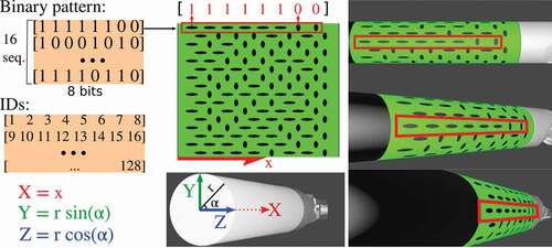
Figure 1. Our binary pattern encoded on a green marker. The pattern is composed of 16 sequences of 8-bit codes, where each bit is represented by an oriented elliptical feature. The elliptical features in our marker, representing 0s and 1s, were designed to be distinctive even under challenging conditions such as when the surgical tool is at steep angles. Each feature is also associated to a unique ID, to store its 3D position (X, Y, Z) which calculated using the radius and the position of the feature in the marker. The 3D positions remained fixed, and are used by a PnP solver to estimate the marker’s pose.
2.1.2. Marker features
When designing the marker pattern, our goal was to find a type of feature that could be easily used to encode a binary pattern with two classes. One of the classes representing the 0’s, and the other class representing the 1’s of the binary pattern. Additionally, the features on the marker needed to be robust to challenging surgical tool poses. For instance, the further the surgical tool is from the camera, the smaller the features will appear on the image. Likewise, the steeper the angle between the camera and the surgical tool, the more distorted are the features. Therefore, careful consideration was given to the shape of the features since we wanted both a shape that, allowed easy binary classification, and unchanged appearance even under challenging surgical tool poses. In our work, we found empirically that elliptical blobs pointing in opposite directions can be easily detected and distinguished even when the surgical tool is at challenging poses, as shown in .
2.1.3. Binary marker pattern
Our proposed marker pattern is composed of two distinct features which encode binary sequences in the marker pattern as shown in . The introduced pattern has a total of 16 binary sequences. Each sequence corresponds to a row on the pattern and is formed by 8 features. These features encode either a 1 or a 0. All the sequences start with a 1 and end with a 0 to avoid symmetries. To create the binary pattern we follow two steps. Firstly, we generate all the possible sequences which are permutations of 8-bit that start with 1 and end with 0. Secondly, we create groups of 16 randomly selected sequences. From all these groups, we choose the group with the sequences that are more distinctive to each other. The distinctiveness between the two sequences is measured using a bitwise XOR. The chosen group is composed of 16 sequences with 8-bit codes and therefore, there are a total of 128 features in the marker. Each of the 128 features is assigned an ID and a 3D coordinate (X, Y, Z) relative to the marker’s coordinate frame. This 3D coordinate is calculated using the radius of the tool and the position of the feature’s centroid in the marker, as shown in . The IDs and 3D coordinates of the marker features are used as input to a PnP solver (explained in Sec. 2.2.4) to estimate the pose of the marker. The designed marker is for cylindrical tools and it can be scaled to fit different tool diameters. For a tool of 8 diameter, the marker has a height of 25.13
, and a width of 30.34
.
2.2. Surgical tool tracking
As shown in , the tracking method consists of:
Figure 2. Surgical tool tracking using our enhanced marker.
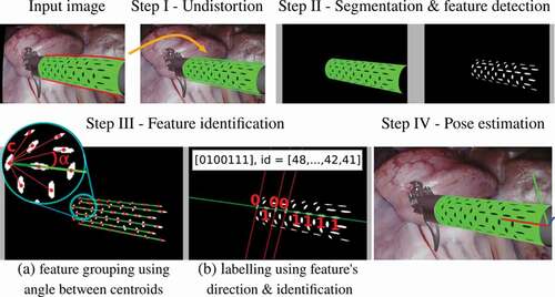
2.2.1. Step I – undistort the input image
Firstly, the input laparoscopic image is undistorted using the tangential and radial camera distortion parameters. This is necessary to ensure that the centroid of the marker features which belong to the same sequence, lie on a straight-line.
2.2.2. Step II – segment the marker and detect features
Then, the undistorted image is converted into the HSV colour space to segment the marker and detect features on its pattern. Firstly, the marker is segmented using its green colour, which is done by thresholding the Hue, Saturation and Value channels using a range of values that were empirically defined. Specifically, we segment the green colour using H between , S between
and V between
. After segmenting the green marker, the black elliptical features inside it are also segmented. To distinguish the black features from the green part of the marker we use the V channel only. The V channel is sufficient to distinguish green from black, since black pixels have V intensities which are significantly lower than the green pixels around it. All the pixels in the marker are classified as green or black. Then, the black pixels are grouped together using a standard connected-component labelling. Each of the connected-components corresponds to a detected feature.
2.2.3. Step III – identify features
After detecting the marker features, the next step is to identify each of those features. The goal of identifying the features is to get their 3D positions relative to the marker’s coordinate frame. These 3D positions will be later used to estimate the pose of the marker, as explained in step 2.2.4. The features are identified in groups of 8. The reason for grouping the features before identifying them is that, as shown in , each line in the binary pattern forms a 8-bit code, starting with 1 and ending with 0. Since each 8-bit code is unique, identifying the features is as simple as decoding each group of 8 features located on a straight-line. To find which features lie on a straight-line we first calculate the pixel centroid of each detected feature using the image moments of the contours of each feature. Then, using all the centroids, the features are grouped into sequences by finding 8 centroids that lie on the same line. Given one of those centroids , the angles that the other centroids form with
are calculated as the inverse tangent of the difference of their image coordinates, as shown in . Then, the angle values are sorted. If there are 7 adjacent angles in the sorted order which have approximately the same value, then those centroids are grouped to the same sequence as
, forming a group of 8 features. Thirdly, after grouping the centroids into sequences, each feature is classified as 1 or 0. To classify each feature, a 2D line is fitted to the shape of the feature, using a least-squares method, to determine the feature’s direction. If the feature’s direction is aligned with the line formed by the centroids belonging to the sequence, it is classified as 1, otherwise as 0, as shown in . Finally, after classifying all the features in a group, the features can finally be identified by assigning an ID value from 1 to 128. The features can be uniquely identified since each sequence has a unique binary code starting with a 1 and ending with a 0. A minimum of three sequences need to be identified to estimate the marker’s pose. Otherwise, the tracking method repeats for the next input image.
2.2.4. Step IV – estimate the marker’s pose
For each identified feature, a 3D-to-2D correspondence of a feature’s centroid is obtained. The 3D corresponds to the position of the centroid in the marker’s coordinate frame and the 2D corresponds to the pixel coordinates of the detected feature’s centroid in the image plane, as explained in Sec. 2.1 and . To estimate the marker’s pose, all the identified features and therefore all the 3D-to-2D correspondences, are used as input to a RANSAC implementation of an EPnP solver (Lepetit et al. Citation2009). After this step, the tracking algorithm is repeated for the next input image.
Multiple surgical tools can be tracked simultaneously by using multiple markers with unique binary codes. Then, each marker can be segmented and analysed individually. The code to generate these binary markers and the tracking method will be made publicly available.
3. Experimental results
3.1. Experimental set-up
The laparoscope of a da Vinci® robot was used to capture video data for our ex vivo experiment. Since our method requires monocular input, only the video from the left-stereo laparoscope camera is used. The video resolution is
. Our tracking method was implemented in Python and runs at 55
on a computer with an Intel® Core (i7-8700) on CPU
3.20
and 16 GB RAM.
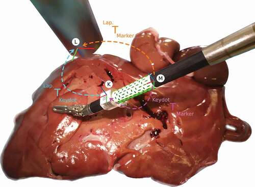
We chose to compare our binary cylindrical marker with the method in (Zhang et al. Citation2017) since it is the most recent state-of-the-art cylindrical marker that is available online for 6DoF pose estimation. For our ex vivo experiments, a da Vinci® surgical tool with 8 diameter was used. The ex vivo data captures the surgical tool with an attached cylindrical marker, over porcine liver and kidneys, as shown in . To enable fair comparison with the state-of-the-art method (Zhang et al. Citation2017), we used the da Vinci Research Kit, dVRK (Kazanzides et al. Citation2014), to control the surgical tool through a predefined set of poses. Using this set of poses, we recorded data twice, once for our binary marker and once for the state-of-the-art marker. For each recording, these two markers were wrapped around the same region of the surgical tool and therefore, they went through the same range of poses. Both markers were printed on sticky paper to be rigidly attached to the shaft of the surgical tool. A KeyDot® marker was also rigidly attached to the surgical tool to collect ground truth data. The KeyDot is a planar marker, therefore, we 3D printed an adapter to create a planar surface around the cylindrical surgical tool using a Statasys® Objet500, with an accuracy of 100 microns.
3.2. Ex vivo experiment
Figure 3. Ex vivo experiment, where the surgical tool moves over a porcine liver, and illustration of the coordinate frames and their transformations. The coordinates frames represent the Marker (M), the KeyDot (K), and the Laparoscope (L).
During the ex vivo experiment, the robot moves the surgical tool through a set of predefined poses as explained above. This set of poses is used to capture image data for both our binary marker and for the state-of-the-art marker (Zhang et al. Citation2017). Specifically, first we attached our binary marker and captured the image data. Then, we replaced our binary marker by the state-of-the-art marker on the same region of the shaft and repeated the image capturing by controlling the robot through the same set of predefined poses. Both markers go through the same set of poses to guarantee fair comparison of the markers, as shown in . For each marker, a total of 1,000 frames were captured for evaluation, capturing the surgical tool in different poses. These poses include the surgical tool at a working distance between 50 and 100 , and a range of different angles. The range of angles was [−40°, 40°] for Roll, [−40°, −5°] Pitch, and [−30°, 30°] Yaw, which are within the ranges defined by (Zhang et al. Citation2017).
3.2.1. Coordinate transformations
The ground truth pose of a cylindrical marker, , is calculated as:
where, is the coordinate transformation from the cylindrical marker to the KeyDot, and
from the KeyDot to the laparoscope. When the surgical tool moves to a different pose, or when the laparoscope moves, both
and
change their values. On the contrary,
does not change since both the Keydot and the cylindrical marker are rigidly attached to the same surgical tool. Therefore, the static transformation,
, is calibrated before calculating the ground truth poses for each of the cylindrical markers. This transformation was calculated twice, once for our green marker, and once for the state-of-the-art marker, since each cylindrical marker has its own independent coordinate frame. These transformations were carefully measured and refined until the marker’s features achieved subpixel accuracy when reprojected.
3.2.2. Illumination conditions
For further validation, we evaluated both markers under different light conditions. Specifically, we used a STORZ® endoscopic light source, and we captured images with that light source at 25%, 50%, 75% and 100% of the maximum light intensity. For each of these light intensities, the robot went through the same set of predefined poses.
3.3. Simulation experiment
For further validation, VisionBlender (Cartucho et al. Citation2021) was used to create a synthetic laparoscopic dataset, shown in . The goal of using the synthetic dataset is to add variability to the performance evaluation study, in terms of the marker pose, background surgical scene, and material properties of the shaft and marker. The simulation environment consists of two parts, in the foreground (a), a virtual surgical tool with a marker attached to its shaft, and in the background (b), a endoscopic video captured from a real physical laparoscope. The background videos capture a diverse set of scenes of porcine cadavers from the SCARED dataset (Allan et al. Citation2021). To further increase variability, multiple virtual surgical tools were used in our simulation. To introduce variability to the appearance of the virtual tool and the marker, their material properties such as surface roughness and specular reflection, have been constantly changed between frames. Similarly, between frames the light intensity changes, to test the markers under both brighter and dimmer illumination conditions. In our simulated videos, the surgical tools move around a predefined set of poses within a range of distances and angles. Similar to our ex vivo experiment, in the simulation, the tool’s distance to camera and rotation is restricted within the range defined by the state-of-the-art (Zhang et al. Citation2017). Specifically, the camera-to-marker distance is within 60 to 130 and for testing rotation the angles vary between [−76°, 76°] in Roll, [−71°, 71°] in Pitch and [−62°, 62°] in Yaw. The diameter of the simulated surgical tool is 8
. On simulation, when the tool goes through the range of predefined poses, two videos are created simultaneously namely, one video with the marker proposed in (Zhang et al. Citation2017), and another video with our binary marker. For each marker, a total of 23,000 synthetic video frames were generated to compare the two methods.
3.4. Tracking multiple tools
Multiple binary markers, each with its unique binary pattern, can be generated to track multiple surgical tools simultaneously. To track multiple tools, our method processes the largest green regions of the input image, where
is the number of markers that are expected to be detected. When the
markers are detected the multiple tool tracking is successful, and the pose of all the tools is calculated. For the multiple tool tracking experiment, we used
binary markers, which were rigidly attach to two separate surgical tools. Then, a total of 150 images were collected, capturing these two surgical instruments at multiple poses. In those images, both the markers were inside the field of view of the camera and the surgical tools did not occlude each other.
3.5. Performance evaluation
The performance of our method has been evaluated with the ex vivo and simulation experiments by comparing the ground truth data with the poses predicted by our method and the method proposed in (Zhang et al. Citation2017). The method in (Zhang et al. Citation2017) was chosen for comparison since it is the most recent publicly available state-of-the-art method for 6DoF pose estimation with a cylindrical marker. The translation error was calculated using the mean absolute error in . The rotation error was calculated using the inner product of unit quaternions (Huynh Citation2009), which gives an error in the range [0°, 90°].
As shown in , our binary marker outperformed the state-of-art. The most significant difference is the accuracy of the predicted orientation of the surgical tool, which is represented by the rotation error. Our binary marker predicts the orientation of the surgical tool with mean errors as low as 0.45° and with low standard deviation values, which indicates that the values tend to be close to that mean error. Conversely, the state-of-the-art marker predicts the orientation of the surgical tool with around 4° error and a high standard deviation which goes up to 11°, indicating that the values are spread out over wider errors. Regarding predicting the position of the surgical tool, which is represented by the translation error, our binary marker again outperformed the state-of-the-art achieving sub-millimetre errors between 0.28 in the ex vivo, and 0.47
in the simulation experiment, compared to the state-of-the-art which scored errors between 0.55
in the ex vivo and 2.25
on simulation. Similar to the rotation error, the standard deviation of the translation errors are significantly lower for our binary marker than the state-of-the-art marker. The standard deviation of the translation error was always smaller than 1
for our binary marker, while it ranges between 1.20 and 8.82
for the state-of-the-art marker. The errors for the simulation experiment are larger than the ones of the ex vivo experiment since on simulation the surgical tool goes through a wider variety of poses, illumination conditions and material properties which affect properties such as the specular reflection of the marker.
In the ex vivo experiment the two markers go through the same set of predefined poses under different illumination conditions. The results show that our binary marker had a more robust performance under different illumination conditions, achieving similar results in all the conditions. Conversely, the state-of-the-art marker had a worse performance both in translation and rotation error when the light intensity was set to 25% of the maximum. At 25%, the state-of-the-art marker had both larger errors and a smaller detection rate.
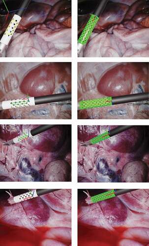
shows image results from the ex vivo experiment. In that figure, it can be noticed that the surgical tool goes through the same set of poses and illumination conditions for both markers to enable fair comparison of the mehods. On the images for the state-of-the-art marker we occluded the KeyDot pattern since this method cannot distinguish the blobs on the KeyDot pattern from the blobs on the cylindrical marker. Conversely, we did not had to occlude the KeyDot on the input images for our method since our method only processes features inside the green region of the image. In , in pose 2 on the orange arrow, we can also see that a specular highlight interferes with the features on the middle region of the marker. In this case, the state-of-the-art method ended up grouping the wrong blobs together, leading to a false predicted pose. Conversely, in our binary marker, the features along the line in the middle were simply ignored. Those features were ignored since due to the specular highlight, the feature centroids were not forming a group of 8 features in a straight line any longer. Still, the other visible lines were correctly detected and used to predict the pose of the marker. Our method can deal with 50% occlusion along the tangential direction of the marker, as only 3 of the 6 visible lines are required for 6DoF pose estimation.
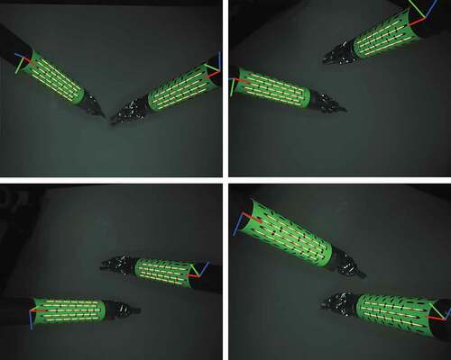
shows results from the simulation experiment. On the top image, we can see another example were a specular highlight interferes with the state-of-the-art marker leading to an outliers on the estimated pose, while our method ignores the line with a specular highlight and predicts the pose correctly. In that figure, it is also visible that in our simulation we tested a varied set of backgrounds, which come from images captured by a real physical endoscope, a varied set of poses and that the material properties of the marker are constantly changing between different frames. By changing the material properties we change, for example, the presence or not of specular highlights on the marker’s surface.
Figure 4. Results on ex vivo experiment, where a surgical tool of the da Vinci® robot goes through a predefined set of illumination conditions and poses. At each pose two images are captured, one for our binary marker, shown on the right column, and one for the state-of-the-art marker (Zhang et al. Citation2017), shown on the left column. The surgical tool are moving over an ex vivo porcine liver.
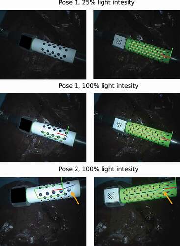
Figure 5. Results on simulation experiment.
shows results from the multiple tool tracking experiment. On 150 images capturing two sugical tools simultaneously, our method was able to predict the pose of both surgical instruments for 95% of those images.
Figure 6. Results on tracking multiple tools.
4. Discussion and conclusion
In this paper, an enhanced cylindrical marker was introduced for 6DoF tracking of surgical tools which achieves sub-millimetre accuracy. Our cylindrical marker encodes a binary pattern using 8 aligned features for each binary sequence. The binary sequences contribute independently to estimate the pose of the surgical tool, making our marker more robust to challenging illumination conditions, such as, when there are specular highlights on the marker. Two experiments were conducted, on simulation and ex vivo data, to compare the performance of our binary marker with the most recent state-of-the-art marker that is available online. All the experiments were conducted carefully to allow a fair comparison between the two markers over the same set of predefined poses and illumination conditions. Our binary marker outperformed the state-of-the-art in speed and accuracy, with significantly lower errors and standard deviations. The performance evaluation verified the robustness of the proposed method to varying illumination conditions and challenging tool poses. Our current tracking method does not incorporate kinematic information which we aim to include it in the future to improve the results even further. We also aim to use our enhanced marker along with kinematic information to continuously update the hand-eye calibration of the robotic system during the operation to improve visual servoing. We also plan to further evaluate the tracking accuracy on challenging situations such as occlusions due to smoke or blood over the marker. Similarly, the simulation environment is to be extended and divided into separate parts to evaluate how each individual parameter, such as illumination, noise, motion blur, and other, influences the tracking accuracy.
Acknowledgments
The authors are grateful for the support from the NIHR Imperial BRC (Biomedical Research Centre), the Cancer Research Uk Imperial Centre, the Royal Society (UF140290) and technical support in the form of tool model CAD data from Intuitive Surgical.
Disclosure statement
No potential conflict of interest was reported by the author(s).
Additional information
Notes on contributors
João Cartucho
João Cartucho is a PhD student in the Hamlyn Centre for Robotic Surgery at Imperial College London, UK. His research focus is in Computer Vision, and Robotic Surgery.
Chiyu Wang
Chiyu Wang is an MRes student in the Hamlyn Centre for Robotic Surgery at Imperial College London, UK. His research focus is in Robotic Surgery.
Baoru Huang
Baoru Huang is a PhD student in the Hamlyn Centre for Robotic Surgery at Imperial College London, UK. Her major research focus is in Computer Vision, Deep Learning and Surgical Augmented Reality.
Dan S. Elson
Dan S. Elson is a Professor of Surgical Imaging and Biophotonics in the Hamlyn Centre for Robotic Surgery, Institute of Global Health Innovation and Department of Surgery and Cancer, UK. Research interests are based around the development and application of photonics technologies to medical imaging and endoscopy.
Ara Darzi
Ara Darzi is the Paul Hamlyn Chair of Surgery at Imperial College London, the Royal Marsden Hospital and the Institute of Cancer Research. He is Director of the Institute of Global Health Innovation at Imperial College London and Chair of Imperial College Health Partners. He is an Honorary Consultant Surgeon at Imperial College Hospital NHS Trust.
Stamatia Giannarou
Stamatia Giannarou is a Royal Society University Research Fellow at the Hamlyn Centre for Robotic Surgery, Imperial College London, UK. Her main research interests include visual recognition and surgical vision.
References
- Allan M, Mcleod J, Wang CC, Rosenthal JC, Fu KX, Zeffiro T, Xia W, Zhanshi Z, Luo H, Zhang X, et al. 2021. Stereo correspondence and reconstruction of endoscopic data challenge. arXiv Preprint arXiv:210101133.
- Cartucho J, Tukra S, Li Y, S Elson D, Giannarou S. 2021. Visionblender: a tool to efficiently generate computer vision datasets for robotic surgery. Comput Methods Biomech Biomed Eng Imag Vis, 9(4):331–338.
- Facil JM, Ummenhofer B, Zhou H, Montesano L, Brox T, Civera J. 2019. Cam-convs: camera- aware multi-scale convolutions for single-view depth. In: Proceedings of the IEEE/CVF Conference on Computer Vision and Pattern Recognition. p. 11826–11835.
- Gadwe A, Ren H. 2018. Real-time 6dof pose estimation of endoscopic instruments using printable markers. IEEE Sens J. 19(6):2338–2346. doi:https://doi.org/10.1109/JSEN.2018.2886418.
- Giannarou S, Ye M, Gras G, Leibrandt K, Marcus HJ, Yang GZ. 2016. Vision-based deformation recovery for intraoperative force estimation of tool–tissue interaction for neurosurgery. Int J Comput Assist Radiol Surg. 11(6):929–936. doi:https://doi.org/10.1007/s11548-016-1361-z.
- Hao R, Özgüner O, Çavuşoğlu MC. 2018. Vision-based surgical tool pose estimation for the da vinci® robotic surgical system. In: 2018 IEEE/RSJ International Conference on Intelligent Robots and Systems (IROS). IEEE. p. 1298–1305.
- Huang B, Tsai YY, Cartucho J, Vyas K, Tuch D, Giannarou S, Elson DS. 2020. Tracking and visualization of the sensing area for a tethered laparoscopic gamma probe. IJCARS. 15(8):1389–1397. doi:https://doi.org/10.1007/s11548-020-02205-z.
- Huynh DQ. 2009. Metrics for 3d rotations: comparison and analysis. J Math Imag Vis. 35(2):155–164. doi:https://doi.org/10.1007/s10851-009-0161-2.
- Jamjoom, Aimun AB, Ammer MA Jamjoom, and Hani J. Marcus. 2020. “Exploring public opinion about liability and responsibility in surgical robotics.„ Nature Machine Intelligence 2.4: 194–196.
- Jayarathne, U. L., McLeod, A. J., Peters, T. M., & Chen, E. C. (2013, September). Robust intraoperative US probe tracking using a monocular endoscopic camera. In International Conference on Medical Image Computing and Computer-Assisted Intervention (pp. 363–370). Springer, Berlin, Heidelberg.
- Jayarathne UL, Chen EC, Moore J, Peters TM. 2018. Robust, intrinsic tracking of a laparoscopic ultrasound probe for ultrasound-augmented laparoscopy. IEEE Trans Med Imag. 38(2):460–469. doi:https://doi.org/10.1109/TMI.2018.2866183.
- Kazanzides P, Chen Z, Deguet A, Fischer GS, Taylor RH, DiMaio SP. 2014. An open-source research kit for the da vinci surgical system. In: IEEE Intl. Conf. on Robotics and Auto. (ICRA); Hong Kong, China. p. 6434–6439.
- Kendall, Alex, Matthew Grimes, and Roberto Cipolla. 2015. “Posenet: A convolutional network for real-time 6-dof camera relocalization.„ In Proceedings of the IEEE international conference on computer vision, p. 2938–2946.
- Kopf, J., Rong, X. and Huang, J.B., 2021. Robust consistent video depth estimation. In Proceedings of the IEEE/CVF Conference on Computer Vision and Pattern Recognition, pp. 1611–1621.
- Lepetit V, Moreno-Noguer F, Fua P. 2009. Epnp: an accurate o (n) solution to the pnp problem. IJCV. 81(2):155. doi:https://doi.org/10.1007/s11263-008-0152-6.
- Liu X, Plishker W, Shekhar R. 2021. Hybrid electromagnetic-aruco tracking of laparoscopic ultrasound transducer in laparoscopic video. J Med Imag. 8(1):015001. doi:https://doi.org/10.1117/1.JMI.8.1.015001.
- Ma L, Wang J, Kiyomatsu H, Tsukihara H, Sakuma I, Kobayashi E. 2020. Surgical navigation system for laparoscopic lateral pelvic lymph node dissection in rectal cancer surgery using laparoscopic-vision-tracked ultrasonic imaging. Surg Endosc. 1–12. doi:https://doi.org/10.1007/s00464-020-08153-8.
- Mahendran, S., Ali, H. and Vidal, R., 2017. 3d pose regression using convolutional neural networks. In Proceedings of the IEEE International Conference on Computer Vision Workshops, pp. 2174–2182.
- Reiter, A., Allen, P.K. and Zhao, T., 2012, June. Articulated surgical tool detection using virtually-rendered templates. In Computer Assisted Radiology and Surgery (CARS), pp. 1–8.
- Reiter, A., Allen, P.K. and Zhao, T., 2012, October. Feature classification for tracking articulated surgical tools. In International Conference on Medical Image Computing and Computer-Assisted Intervention (pp. 592–600). Springer, Berlin, Heidelberg.
- Shao, J., Luo, H., Xiao, D., Hu, Q. and Jia, F., 2017. Progressive hand-eye calibration for laparoscopic surgery navigation. In Computer Assisted and Robotic Endoscopy and Clinical Image-Based Procedures (pp. 42–49). Springer, Cham.
- Wang, T., Wang, Y. and Li, M., 2020, October. Towards accurate and interpretable surgical skill assessment: A video-based method incorporating recognized surgical gestures and skill levels. In International Conference on Medical Image Computing and Computer-Assisted Intervention (pp. 668–678). Springer, Cham.
- Wu SY, Aurup C, Sanchez CS, Grondin J, Zheng W, Kamimura H, Ferrera VP, Konofagou EE. 2018. Efficient blood-brain barrier opening in primates with neuronavigation-guided ultrasound and real-time acoustic mapping. Sci Rep. 8(1):1–11. doi:https://doi.org/10.1038/s41598-018-25904-9.
- Ye, M., Zhang, L., Giannarou, S. and Yang, G.Z., 2016, October. Real-time 3d tracking of articulated tools for robotic surgery. In International conference on medical image computing and computer-assisted intervention (pp. 386–394). Springer, Cham.
- Zhan, J., Cartucho, J. and Giannarou, S., 2020, May. Autonomous tissue scanning under free-form motion for intraoperative tissue characterisation. In 2020IEEE International Conference on Robotics and Automation(ICRA) (pp. 11147–11154). IEEE.
- Zhang, L., Ye, M., Chan, P.L. and Yang, G.Z., 2017. Real-time surgical tool tracking and pose estimation using a hybrid cylindrical marker. International journal of computer assisted radiology and surgery, 12(6), pp.921–930.
- Zhang L, Ye M, Chan PL, Yang GZ. 2017. Real-time surgical tool tracking and pose estimation using a hybrid cylindrical marker. IJCARS. 12(6):921–930. doi:https://doi.org/10.1007/s11548-017-1558-9.