
 ?Mathematical formulae have been encoded as MathML and are displayed in this HTML version using MathJax in order to improve their display. Uncheck the box to turn MathJax off. This feature requires Javascript. Click on a formula to zoom.
ABSTRACT
This paper introduces and validates a new technique for analysing six degrees-of-freedom shoulder kinematics using four-dimensional computed tomography (4DCT), which uses a single vertebra to reference thoracic motion. Differences between the vertebra and International Society of Biomechanics (ISB) torso coordinate systems had an average RMSE of 11.6º and no statistical differences were found regarding range of motion. The errors associated with repeated analysis ranged from 0.2 mm to 3.4 mm, and 0.9º to 1.1º. Overall, the technique has been shown to be repeatable, and using a single vertebra is comparable to using the ISB torso coordinate system.
KEYWORDS:
Introduction
Analyzing shoulder girdle kinematics is challenging as the shoulder is comprised of a complex group of highly mobile joints (Krishnan et al. Citation2019). Motion of the shoulder is accomplished through a synergistic collaboration of four joints: the glenohumeral, scapulothoracic, acromioclavicular, and sternoclavicular. The glenohumeral and scapulothoracic joints are of particular interest as they are the joints primarily responsible for shoulder motion; the glenohumeral joint accounts for approximately two-thirds of shoulder motion while the scapulothoracic accounts for one-third (Scibek Citation2012). The glenohumeral joint is the most mobile joint in the body formed by the humeral head articulating with the glenoid fossa of the scapula. The range of motion of the humerus is on average 160º of flexion, 150º of abduction, and 60º of external rotation (Gill et al. Citation2020). The scapulothoracic joint represents the articulation of the scapula relative to the thorax. In accordance with the International Society of Biomechanics (ISB) recommended standard, clinical studies often describe scapulothoracic motion as rotations about the three axes: protraction/retraction (internal/external rotation), upward/downward rotation, and anterior/posterior tilt. Rotational values vary between studies based on the type of motion, the measurement technique, and other possible factors. In general, the range of motion of the scapula is on average 25º of retraction, 50º of upward rotation, and 30º of posterior tilting for scapular plane elevation (McClure et al. Citation2001).
Unlike at the elbow or knee which have a primary flexion/extension axis, both shoulder joints have a large range of motion (ROM) in all three directions (Krishnan et al. Citation2019). As such, there are six degrees-of-freedom in the shoulder joints, three translations and three rotations, and all these parameters need to be defined to fully describe shoulder motion (Charbonnier et al. Citation2014). Despite the importance of glenohumeral and scapulothoracic coordination, the glenohumeral joint is most studied in the shoulder (Krishnan et al. Citation2019; Daher et al. Citation2023). Additionally, the limited research on the scapulothoracic primarily focuses on planar motion such as abduction or flexion (Krishnan et al. Citation2019).
There are many challenges researchers face when measuring shoulder kinematics (Charbonnier et al. Citation2014). In the past, kinematics have been analysed using x-ray, MRI, and CT; however, these static or two-dimensional measurements do not truly represent dynamic three-dimensional (3D) motion (Charbonnier et al. Citation2014). Motion capture, with optical or electromagnetic sensors, is another common technique to track shoulder motion; however, this requires external markers making it difficult to palpate and track subcutaneous landmarks, often leading to soft-tissue artefacts (Bourne et al. Citation2011; Jackson et al. Citation2012; Klotz et al. Citation2013; Charbonnier et al. Citation2014). Using bone-fixed markers prevents skin-motion artefact (McClure et al. Citation2001), but its invasiveness is a limiting factor on sample size and the use of local anaesthesia may affect the kinematic validity (Hajizadeh et al. Citation2019). In recent literature, radiographic imaging has been the standard technique using biplane x-ray (Bey et al. Citation2006, Citation2008; Baumer et al. Citation2016), biplane fluoroscopy (Massimini et al. Citation2012; Giphart et al. Citation2013; Kijima et al. Citation2015; Kolz et al. Citation2021), or single-plane fluoroscopy (Nishinaka et al. Citation2008; Kon et al. Citation2008; Matsuki et al. Citation2011). In this approach, a 3D model, usually obtained through CT, is registered to dynamic radiographic images to determine the bones pose throughout a motion. This technique is dynamic and does not suffer from soft-tissue artefact but the size of the imaging volume is limited (Baumer et al. Citation2016) which can be problematic with the large ROM in the shoulder (Krishnan et al. Citation2019). Additionally, a small field of view (FOV) means common landmarks found on the thorax and spine are not usually available and thus scapulothoracic kinematics are often referenced to an external reference such as the scanner’s global coordinate system (Kon et al. Citation2008; Matsuki et al. Citation2011; Kijima et al. Citation2015); this is an obvious disadvantage as any torso motion is erroneously included.
The ISB has recommendations for various landmarks and coordinate system definitions (Wu et al. Citation2005). Briefly, the humeral coordinate system employs the epicondyles as landmarks, and the torso coordinate system uses landmarks on the sternum and spine. To capture all these landmarks, a large FOV is required, approximately 28 cm across and 26 cm axial. Additionally, treating a torso coordinate system as a static reference may be a poor assumption given that the spine is not a rigid body. Moreover, this assumption may be valid when standing but with 4DCT the different motions that are performed require different positioning such as laying on the back or the side.
To address some of these challenges, recent studies have employed four-dimensional computed tomography (4DCT) as it provides a 3D view of the shoulder complex over time (3DCT + time) and can provide dynamic images of the joint (Alta et al. Citation2012; Bell et al. Citation2015; Matsumura et al. Citation2019). Additionally, the technique is non-invasive and does not suffer from soft-tissue artefact. However, this technology is still in its infancy and papers characterising healthy motion of the shoulder using 4DCT are non-existent. Additionally, many studies have not performed a comprehensive validation against a gold standard.
The primary objective of this paper was to describe a new technique for analysing shoulder kinematics which uses 4DCT (and associated anatomical landmarks) and is referred to as the Single-Vertebra Imaged-Based (SVIB) technique. Secondary objectives were to determine whether the vertebra derived local coordinate system is comparable to the ISB thorax derived local coordinate system and to assess repeatability of the proposed technique (SVIB).
Methods
Data acquisition
Following approval from Western’s Research Ethics Board (approval no. 114450), participants were recruited with the inclusion criteria of males 18 years of age or over, and no history of dominant shoulder injury. After obtaining informed consent, participants were checked to ensure they had a healthy range of motion in their dominant shoulder (able to reach behind their back up to at least their lower thoracic vertebrae). Additionally, imaging was reviewed post hoc and any participants that did not have the required anatomical landmarks visible were excluded. A total of four participants (average age 27 ± 8) were included in this study. A CT scanner (Revolution CT Scanner, GE Healthcare, Waukesha, Wisconsin, USA) was used to image the shoulder. First, a localiser scan was used to determine the proper field of view, then a static scan with the participant in a neutral position, then a second localiser scan after repositioning, and lastly a dynamic scan. The static scan followed standard static imaging protocol (120kV, 211 mA, 1.0s rotation time, axial mode, 512 × 512 matrix, axial) and produced 192 1.25 mm thick slices for a volume of size 250 × 250 × 240mm3. For the static scan, the participant was positioned supine with their head and back supported (with padded foam) to ensure that the scapula was not pressed against the gantry table. The dynamic scan followed a standard dynamic imaging protocol (80kV, 130 mA, 0.35s rotation time, cine mode, 512 × 512 matrix, axial) producing 64 2.50 mm thick slices repeatedly for 21 seconds generating 60 volumes (approximately 2.9 frames per second) of size 450 × 450 × 160mm3. For the dynamic scan, participants performed internal rotation to the back while lying on their non-dominant side. For this motion, the dominant hand starts on the abdomen and is moved around the torso while keeping the elbow flexed, finishing with the participant reaching their hand as far up their back as possible. The dynamic scan included this motion being performed as usual in addition to the participant returning to the starting position. For the purposes of this study only one direction of the motion was analysed and as such only the first 25–35 frames were analysed based on the endpoint of motion. To ensure the motion was properly executed, a demonstration was given before the scan and participants were able to practice the motion, additionally, a technologist remained in the scanner room during the scan and counted throughout the scan to ensure the motion was performed at the correct speed such that the motion was fully completed within the scan time. The scan duration (approximately 10 seconds to reach the final position and 10 seconds to return) was selected to prevent any motion blurring by maintaining a deliberately slow speed. However, participants exhibited slight variations in time, as they were instructed to maintain a continuous pace rather than rushing to complete the motion if they felt they were moving too slowly.
Each localiser scan has a dose length product (DLP) of 8 mGy*cm, the static scan has a DLP of 281 mGy*cm, and the dynamic scan has a DLP of 428 mGy*cm. Therefore, using the effective dose conversion factor for a typical chest CT (0.014 mSv*mGy−1*cm−1) (American Association of Physicists in Medicine Citation2008), the effective dose of the entire procedure is estimated at 10.1mSv.
Kinematic analysis (SVIB)
Using the scans, reconstructed 3D bone models of the proximal humerus, scapula, and T1 vertebra were created in 3D Slicer (www.slicer.org, Version 4.11) using a semi-automated reconstruction technique. This consists of thresholding the bone, followed by manual cleanup, and finally applying a smoothing function. Each of these models were made for the static scan and for every other frame of the dynamic scan. The static models were registered to each dynamic model using an iterative closest point (ICP) algorithm (Besl and McKay Citation1992) performed in 3D Slicer via the CMFregistration extension (cmf.slicer.org). The result of the registration was a transformation matrix describing the position of each dynamic model relative to its respective static model.
Anatomical landmarks were then identified on the static scan and used to create coordinate systems. All landmarks are manually selected apart from humeral origin, which is calculated based on sphere to humeral head registration. Specifically, multiple points are randomly selected on the articular surface to generate a best fit sphere. The humerus follows a modified ISB coordinate system where the axes are mathematically aligned to the scapula coordinate system, which is shown to have no statistical difference in range of motion calculation for an abduction motion (Levasseur et al. Citation2007). The scapula and vertebra coordinate systems are based on the ISB recommendations (Wu et al. Citation2002, Citation2005), although the scapula origin is placed at the glenoid centre rather than the acromion. The local coordinate systems, summarised in , are defined as the following:
Figure 1. Local coordinate systems for the (a) humerus, (b) scapula and (c) vertebra.
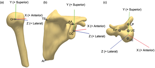
Humerus coordinate system
The origin is located at the centroid of a sphere fit to the articular surface of the humeral head (GH). The humeral Zh-axis (+lateral), Xh-axis (+anterior), and Yh-axis (+superior) are defined to be coincident with the respective scapular axes (Levasseur et al. Citation2007).
Scapula coordinate system
The origin is located at the glenoid centre (GC), defined as the midpoint along a vector connecting the most inferior and superior points on the glenoid. The vector from the trigonum spinae scapulae (TS) to the acromial angle (AA) is defined as the Zs-axis (+lateral). The vector perpendicular to the plane formed by the inferior angle (AI), TS, and AA is the Xs-axis (+anterior). The Ys-axis (+superior) is the cross product of the Zs- and Xs-axes (Wu et al. Citation2005).
Vertebra coordinate system
The origin is located at the midpoint between the centres of the upper endplate (UE) and the lower endplate (LE). The vector from LE to UE is defined as the Yv-axis (+superior). The vector parallel to a line joining the left pedicle (LP) and right pedicle (RP) is the Zv-axis (+lateral). The Xv-axis (+anterior) is the cross product of the Yv- and Zv-axes (Wu et al. Citation2002).
These coordinate systems form two joint coordinate systems (JCS), which consist of a reference and a moving coordinate system. The transformation matrix between the reference (r) and the moving (m) coordinate system for each frame i is calculated as follows:
where the matrices and
define the transformations between the static models and the global frame (G) for the reference and moving frames, respectively. The matrices
and
are the transformations obtained through registration of the static models to the dynamic models for each frame i for the reference and moving frames, respectively. Note that the matrices are pre-multiplied due to the registration transformations being calculated in the global frame.
The scapulothoracic JCS describes the scapula position relative to the spine, decomposed into translations and a standard Y-X’-Z’’ rotation sequence (Wu et al. Citation2005). Positive rotations about the scapula axes are labeled as protraction (Y), medial/downward rotation (X’), and posterior tilting (Z’’). The glenohumeral JCS describes the humerus relative to the scapula, decomposed into translations and a X-Z’-Y’’ rotation sequence; note that this is different than the ISB recommended Y-X’-Y’’ sequence as it has been shown to have singularity issues when approaching elevation angles of 0º (Šenk and Chèze Citation2006; Phadke et al. Citation2011). Positive rotations about the humeral axes are labeled as adduction (X), flexion (Z’) and axial rotation (Y’’), all rotations follow the right-hand rule for positive axes. All matrix multiplications and decompositions were performed in MATLAB (MathWorks, Version R2020a).
Data and statistical analysis
The conventional (ISB) JCS for the scapula uses the thorax as the reference, rather than a single vertebra. However, based on an individual’s bodily proportions, the required anatomic landmarks for the thorax are not necessarily in the FOV of all scans, thus it is important to compare the differences between the two references. For the participants of this study, the necessary landmarks were available; therefore, coordinate systems were created for both the T1 vertebra (Wu et al. Citation2002) and the thorax.
The ISB thorax coordinate system is defined as the following: The origin is located at the Incisura Jugularis (IJ). The vector connecting the midpoint between xiphoid process (PX) and T8, and the midpoint between IJ and C7 is defined as the Yt axis (+superior). The vector perpendicular to the plane formed by IJ, C7, and the midpoint between PX and T8 is defined as the Zt axis (+lateral). The Xt axis (+anterior) is the cross product of the Yt- and Zt-axes (Wu et al. Citation2005).
The transformation between the two coordinate systems was calculated and decomposed into a Y-X’-Z’’ rotation sequence. The rotational differences were used to calculate an average root-mean-square error (RMSE). In addition, the kinematics of the scapula over the entire internal rotation to the back motion were analysed. The relationship between the two kinematic pathways (translations and rotations throughout the motion) was compared with the Pearson correlation coefficient. Values for ROM were calculated as the difference between the maximum and minimum values. This was done for all six degrees of freedom using both the vertebra and thorax references for each participant. Average differences in ROM values between the two coordinate systems were calculated. An analysis of variance (ANOVA) test was done to determine if a statistical difference could be found in any ROM calculation between the two coordinate systems. Statistical significance was set as p < 0.05. All statistical analysis was performed in MATLAB (MathWorks, Version R2020a).
The technique for measuring shoulder kinematics is a complicated multistep process, and each step can introduce error, especially when performed manually; thus, it is important to assess the repeatability of the process. To assess this, the model making, coordinate system creation, and registration steps were repeated thrice by the same investigator for the scans of one participant (age 25) and the results compared. For each degree of freedom in the scapula JCS and humeral JCS, the standard deviation at each individual time point was determined and used to calculate an average standard deviation. Additionally, the differences in ROM were also assessed in terms of mean absolute deviation (MAD). Lastly, the repeatability of landmark selection was assessed by manually selecting the required landmarks for all bones five times for each participant. Landmark repeatability was assessed by looking at the average standard deviations of landmark points and of coordinate system orientation.
Results
Vertebra vs thoracic comparison
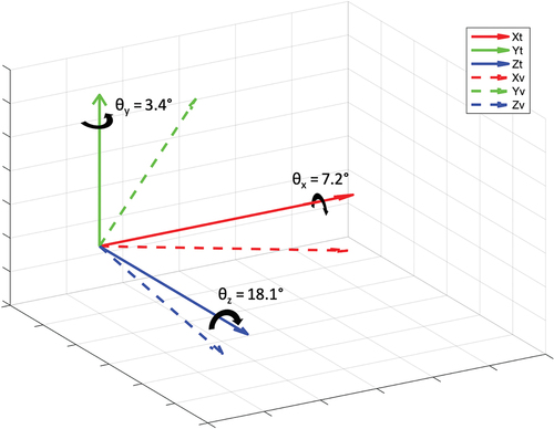
On average, compared to the ISB thoracic coordinate system, the vertebra coordinate system is rotated 3.4º externally (Y-axis), 7.2º medially (X-axis), and 18.1º anteriorly (Z-axis). The average coordinate frame positions are shown in . These rotational errors correspond to an average RMSE of 11.6º.
Figure 2. Average position of the vertebra coordinate system (– –) relative to the average thorax coordinate system (–) which is rotated 3.4º around the Y-axis, 7.2º around the X-axis, and 18.1º around the Z-axis.
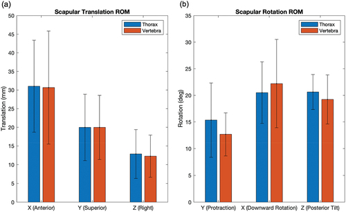
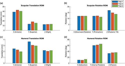
As expected, the thorax and vertebra series are not identical, but they have a strong linear correlation, the mean Pearson correlation coefficient was 0.915 with a median value of 0.996. The kinematic pathways follow a similar trend with an offset present (). The average offset of the vertebra pathway relative to the thorax was −6.4 mm, and −1.4º (). The average signed difference between the spine- and thorax-referenced scapula ROM was 0.3 mm and 0.8º while the average absolute difference was 2.7 mm and 2.5º (). Furthermore, no statistical differences were found for any range of motion calculation (), with p-values ranging from 0.53 to 0.99.
Figure 3. Six degree of freedom kinematics of the scapula (translation in the (a) anterior, (b) superior, and (c) lateral directions, and rotations (d) protraction, (e) downward rotation, and (f) posterior tilt) relative to a vertebra coordinate system (– –) and a thorax coordinate system (–) for four participants. Average translational difference was −6.4 mm, and average rotational difference was − 1.4º.
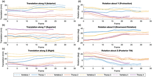
Figure 4. Average range of motion of the scapula for (a) translational and (b) rotational degrees of freedom relative to a thorax coordinate system (blue) and vertebra coordinate system (red) for four participants. Average translational differences were 0.3 mm (signed) and 2.7 mm (absolute), average rotational differences were 0.8º (signed) and 2.5º (absolute).
Repeatability
Regarding repeatability, for the scapula JCS, the average translational standard deviation was 3.4 mm and the average rotational standard deviation was 1.1º (). For the humeral JCS, the average translational standard deviation was 0.2 mm and the average rotational standard deviation was 0.9º (). For the ROM calculations in the scapula JCS, the translational MAD was 1.1 mm and the rotational MAD was 0.5º (). For the ROM calculations in the humeral JCS, the translational MAD was 0.2 mm and the rotational MAD was 1.4º (). For both JCS, the Y-axis (superior-inferior) had the largest discrepancy in translation and the Z-axis (medial-lateral) had the largest discrepancy in rotation.
Figure 5. Threefold repeatability (blue, red, and green series each represent one trial) of scapulothoracic (a) translational and (b) rotational kinematics, and glenohumeral (c) translational and (d) rotational kinematics. Average standard deviations were (a) 3.4 mm (b) 1.1º (c) 0.2 mm (d) 0.9º.
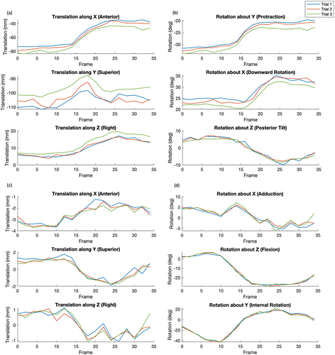
Figure 6. Range of motion calculations for three trials (blue, red, and green) for scapulothoracic (a) translations and (b) rotations, and glenohumeral (c) translations and (d) rotations. Mean absolute deviations were (a) 1.1 mm (b) 0.5º (c) 0.2 mm (d) 1.4º.
For landmark selection repeatability, the scapula, humerus, and vertebra selected points had, on average, a standard deviation of 0.24 mm, 0.27 mm, and 0.23 mm, respectively; the total average standard deviation was 0.25 mm. For the scapula the AI landmark had the minimum standard deviation (0.17 mm) and the TS had the maximum (0.33 mm). For the vertebra the UE had the minimum standard deviation (0.17 mm) and the LE had the maximum (0.30 mm). Regarding differences in the resultant coordinate systems, the scapula, humerus, and vertebra origins had average standard deviations of 0.24 mm, 0.27 mm, and 0.18 mm, respectively. The scapula and humerus had an average standard deviation of 0.18º of rotation about the coordinate systems axes, while the vertebra had a standard deviation of 0.66º on average about the axes.
Discussion
The objectives of this paper were to describe the SVIB technique for analysing shoulder kinematics and compare the differences between the single vertebra coordinate system to the ISB thorax coordinate system in addition to assessing the repeatability of the SVIB technique. Results from this study indicate that, as expected, there are discrepancies between the coordinate systems, but these differences were found to be less than 11.6º on average (), but do show similar trends (). Furthermore, when looking at entire ROM over the dynamic scans (), no statistical differences were found for any degree of freedom (translation: anterior/posterior, superior/inferior, medial/lateral; rotation: protraction/retraction, upward/downward, anterior/posterior). It should be noted that the absence of a difference is not necessarily indicative of equivalence. However, given that the p-values were relatively high (0.53 to 0.99), the probability of a difference is low. Thus, ROM values can be accurately compared to other studies that have used an ISB thorax coordinate system. Overall, it has been demonstrated that it is sufficient to treat the vertebra and thorax systems as comparable in the scapula JCS.
A restriction of CT-based imaging is that certain movement types, such as a full abduction, are not possible due to the scanner’s narrow bore (75 cm diameter). The internal rotation to the back motion is one that can be comfortably performed in the scanner. Additionally, because it is a non-planar motion that requires all degrees of freedom to perform, it is challenging to examine with other imaging techniques, but showcases the full potential of the SVIB technique. Furthermore, internal rotation behind the back is uncommonly studied in the literature, but it is an important motion to study as it is essential in many activities of daily living (Langer et al. Citation2012; Rojas et al. Citation2020), restriction of this motion is also a common disadvantage of reverse shoulder arthroplasties (Rojas et al. Citation2020).
A study by Kolz et al. (Citation2021) looked at static internal rotation poses in reference to a neutral pose. Their results showed less scapulothoracic ROM (10º medial rotation, 5º posterior tilt) than the values determined using the SVIB technique (13º protraction, 22º medial rotation, 19º posterior tilt); however, our results show that the maximum and minimum rotations are not necessarily at the endpoints of motion, which may partially contribute to the discrepancy. Additionally, the neutral position used by Kolz et al. for ROM reference had the humerus in an anatomically neutral pose, whereas our study had the humerus internally rotated such that the hand rested on the abdomen. When looking at Kolz et al. glenohumeral kinematics, the ROM results more closely aligned with ours apart from internal rotation (80º vs 60º); however, the differences in starting positions could again account for the discrepancy.
The ISB thorax coordinate system landmarks require a large field of view to capture, and others have proposed alternative thorax coordinate systems to address the issue. Baumer et al. (Citation2016) conducted a study where they created thorax coordinate systems using various rib pairs. The rib3:rib4 pair had the lowest error compared to ISB thorax, with an RMSE of 4.4º, while the highest had an RMSE of 26.1º (Baumer et al. Citation2016). One limitation of a rib-based coordinate system is the relative motion of ribs during breathing which may introduce errors when measuring dynamic motion. The largest error for the rib coordinate system was internal/external rotation (Baumer et al. Citation2016), while the vertebra coordinate system had the largest error with anterior/posterior rotation. This relative anterior tilting of the T1 vertebra compared to the thorax is expected based on the natural kyphotic curvature of the thoracic vertebrae, this presents as the vertebral body, and subsequently the coordinate system, to appear anteriorly tipped. The advantages of using the T1 vertebra are that it is a distinguishable landmark that is easily identifiable in scans and convenient to include in a narrow field of view as it is aligned at a similar level to the glenohumeral joint.
The results of this study also indicate that the SVIB technique is repeatable. The largest difference when looking at kinematics was scapulothoracic translation in the inferior/superior direction (). This direction closely aligns with the axial CT direction, which only has a slice thickness of 2.5 mm. This value is comparable in magnitude to the total translational RMSE of 2.6 mm. Thus, a single slice difference could contribute to most of the error. Glenohumeral translational RMSE was much smaller at only 0.3 mm, and both JCS had rotational RMSE of about 1º. This suggests that the largest source of error is the T1 vertebra models, as scapula or humerus model differences would result in larger glenohumeral discrepancies. When looking at ROM values (), the errors are similar to the RMSE apart from scapulothoracic translations in which the mean error was only 1.8 mm. Overall, the error is reasonably small, but it is important to know the limitations of this technique. Regarding landmark selection, the errors were relatively small. The selected points on average had a standard deviation of only 0.25 mm; the impact on coordinate system creation was also minimal, with translational deviations less than 0.3 mm and rotational deviations less than 0.7º.
One major limitation of this technique is the time to conduct the analysis. The most time-consuming step is bone model reconstruction for every frame of motion, additionally, the skill to properly make bone models needs to be learned. The consequences of this are smaller study sample sizes and interpolation of kinematics, which in this study meant only every other frame was analysed. This study only included the male sex and because the scans had to include landmarks for the ISB thorax coordinate system, this resulted in participants that had short torsos. This is a limitation as there is evidence that a participant’s sex and anthropometry can influence the calculation of shoulder kinematics (Lavaill et al. Citation2022). Additionally, there was variability in how participants performed the motion as it was unconstrained, and the final arm position was dictated by each participant’s individual maximum range. It is also important to mention that the assessment of multi-operator reproducibility, which could have offered further insights into the technique’s overall reliability and applicability, was not able to be conducted. Although this study did account for repeatability, it was constrained to a single operator’s involvement because of resource limitations, specifically the availability of adequately trained personnel and time restrictions.
The SVIB approach described in this study can effectively assess dynamic motion, all the necessary landmarks are easy to include in a reduced FOV, and there is no skin motion artefact. Future work will develop a neural network to assist with scan segmentation and model creation. This will not only reduce the time necessary to calculate kinematics, addressing the time limitation, but AI segmentation may also reduce human errors which would subsequently improve the reliability of the bone models. When looking at the repeatability of the SVIB technique, the associated errors are for the whole analysis, including model making, registration, and landmark selection. Each step can introduce errors, so given the relatively small errors over the whole analysis, the SVIB technique is a reliable approach to measure kinematics. For future studies using the SVIB technique, comparisons between different cohorts can still be accurately assessed in terms of both kinematic pathways and ROM. Scapulothoracic motion is typically very challenging to examine; however, with the SVIB technique, an upcoming study plans to measure scapulothoracic and glenohumeral motion in two cohorts of participants to examine differences in ROM with age.
Disclosure statement
No potential conflict of interest was reported by the author(s).
Additional information
Funding
Notes on contributors
James Hunter
James Hunter completed his BEng at the University of Guelph specializing in biomedical engineering. He is now a PhD candidate in the Biomedical Engineering department at Western University. His research utilizes four-dimensional computed tomography to analyze in vivo shoulder kinematics with the goal of improving understanding of shoulder biomechanics in healthy and pathological populations.
Ting-Yim Lee
Ting-Yim Lee is a scientist with the Lawson Health Research Institute’s Imaging Program, an Imaging Scientist at the Robarts Research Institute, a Professor at the Schulich School of Medicine and Dentistry, and a Medical Physicist at St. Joseph’s Health Care London. Dr. Lee’s research program focuses on transforming the way clinicians diagnose by developing the next phase of CT Imaging.
George S. Athwal
George S. Athwal is a clinician scientist and orthopedic surgeon at the Roth|McFarlane Hand and Upper Limb Center and Professor in Surgery at Western University. His area of practice is shoulder and upper extremity reconstruction and trauma. Dr. Athwal has published over 300 scientific articles and 50 book chapters and is an Associate Editor for the Journal of Shoulder and Elbow Surgery and Clinics in Shoulder & Elbow.
Emily A. Lalone
Emily A. Lalone is an Associate Professor in the Department of Mechanical and Materials Engineering Department at Western University. She specializes in shoulder and upper extremity reconstruction and trauma at the Roth|McFarlane Hand and Upper Limb Centre. Her research interests are both interdisciplinary and translational and involve using research from Biomedical and Mechanical Engineering, Medical Imaging, Orthopedic Surgery and Rehabilitation.
References
- Alta TD, Bell SN, Troupis JM, Coghlan JA, Miller D. 2012. The New 4-dimensional computed tomographic scanner allows dynamic visualization and measurement of normal acromioclavicular joint motion in an unloaded and loaded condition. J Comput Assist Tomogr. 36(6):749–9. Internet. doi: 10.1097/RCT.0b013e31826dbc50.
- American Association of Physicists in Medicine. 2008. The measurement, reporting, and management of radiation dose in CT: AAPM report no. 96. [ place unknown].
- Baumer TG, Giles JW, Drake A, Zauel R, Bey MJ. 2016. Measuring three-dimensional thorax motion via biplane radiographic imaging: technique and preliminary results. J Biomech Eng. 138(1):1–5. doi: 10.1115/1.4032058.
- Bell SN, Troupis JM, Miller D, Alta TD, Coghlan JA, Wijeratna MD. 2015. Four-dimensional computed tomography scans facilitate preoperative planning in snapping scapula syndrome. J Shoulder Elb Surg. 24(4):e83–e90. Internet. doi: 10.1016/j.jse.2014.09.020.
- Besl PJ, McKay ND. 1992. A method for registration of 3-D shapes. IEEE Trans Pattern Anal Mach Intell. 14(2):239–256. Internet. doi: 10.1109/34.121791.
- Bey MJ, Kline SK, Zauel R, Lock TR, Kolowich PA. 2008. Measuring dynamic in-vivo glenohumeral joint kinematics: technique and preliminary results. J Biomech. 41(3):711–714. doi: 10.1016/J.JBIOMECH.2007.09.029.
- Bey MJ, Zauel R, Brock SK, Tashman S. 2006. Validation of a new model-based tracking technique for measuring three-dimensional, in vivo glenohumeral joint kinematics. J Biomech Eng. 128(4):604–609. doi: 10.1115/1.2206199.
- Bourne DA, Choo AM, Regan WD, MacIntyre DL, Oxland TR. 2011. The placement of skin surface markers for non-invasive measurement of scapular kinematics affects accuracy and reliability. Ann Biomed Eng. 39(2):777–785. doi:10.1007/s10439-010-0185-1. Internet.
- Charbonnier C, Chagué S, Kolo FC, Chow JCK, Lädermann A. 2014. A patient-specific measurement technique to model shoulder joint kinematics. Orthop Traumatol Surg Res. 100(7):715–719. doi: 10.1016/j.otsr.2014.06.015.
- Daher B, Hunter J, Athwal GS, Lalone EA. 2023. How does computed tomography inform our understanding of shoulder kinematics? A structured review. Med Biol Eng Comput. 61(5):967–989. Internet. doi: 10.1007/s11517-022-02755-1.
- Gill TK, Shanahan EM, Tucker GR, Buchbinder R, Hill CL. 2020. Shoulder range of movement in the general population: age and gender stratified normative data using a community-based cohort. BMC Musculoskelet Disord. 21(1):676. doi:10.1186/s12891-020-03665-9. Internet.
- Giphart JE, Brunkhorst JP, Horn NH, Shelburne KB, Torry MR, Millett PJ. 2013. Effect of plane of arm elevation on glenohumeral kinematics. J Bone Jt Surg. 95(3):238–245. Internet. doi: 10.2106/JBJS.J.01875.
- Hajizadeh M, Michaud B, Begon M. 2019. The effect of intracortical bone pin on shoulder kinematics during dynamic activities. Int Biomech. 6(1):47–53. Internet. doi: 10.1080/23335432.2019.1633958.
- Jackson M, Michaud B, Tétreault P, Begon M. 2012. Improvements in measuring shoulder joint kinematics. J Biomech. 45(12):2180–2183. doi: 10.1016/J.JBIOMECH.2012.05.042.
- Kijima T, Matsuki K, Ochiai N, Yamaguchi T, Sasaki Y, Hashimoto E, Yasuhito S, Yamazaki H, Kenmoku T, Yamaguchi S, et al. 2015. In vivo 3-dimensional analysis of scapular and glenohumeral kinematics: comparison of symptomatic or asymptomatic shoulders with rotator cuff tears and healthy shoulders. J Shoulder Elb Surg. 24(11):1817–1826. Internet. doi: 10.1016/j.jse.2015.06.003.
- Klotz MCM, Kost L, Braatz F, Ewerbeck V, Heitzmann D, Gantz S, Dreher T, Wolf SI. 2013. Motion capture of the upper extremity during activities of daily living in patients with spastic hemiplegic cerebral palsy. Gait Posture. 38(1):148–152. doi: 10.1016/J.GAITPOST.2012.11.005.
- Kolz CW, Sulkar HJ, Aliaj K, Tashjian RZ, Chalmers PN, Qiu Y, Zhang Y, Bo Foreman K, Anderson AE, Henninger HB. 2021. Age-related differences in humerothoracic, scapulothoracic, and glenohumeral kinematics during elevation and rotation motions. J Biomech. 117:110266. Internet. doi: 10.1016/j.jbiomech.2021.110266.
- Kon Y, Nishinaka N, Gamada K, Tsutsui H, Banks SA. 2008. The influence of handheld weight on the scapulohumeral rhythm. J Shoulder Elb Surg. 17(6):943–946. Internet. doi: 10.1016/j.jse.2008.05.047.
- Krishnan R, Björsell N, Gutierrez-Farewik EM, Smith C. 2019. A survey of human shoulder functional kinematic representations. Med Biol Eng Comput. 57(2):339–367. Internet. doi:10.1007/s11517-018-1903-3.
- Langer JS, Sueoka SS, Wang AA. 2012. The importance of shoulder external rotation in activities of daily living: improving outcomes in traumatic brachial plexus palsy. J Hand Surg Am. 37(7):1430–1436. doi: 10.1016/J.JHSA.2012.04.011.
- Lavaill M, Martelli S, Gilliland L, Gupta A, Kerr G, Pivonka P. 2022. The effects of anatomical errors on shoulder kinematics computed using multi-body models. Biomech Model Mechanobiol. 21(5):1561–1572. Internet. doi:10.1007/s10237-022-01606-0.
- Levasseur A, Tétreault P, de Guise J, Nuño N, Hagemeister N. 2007. The effect of axis alignment on shoulder joint kinematics analysis during arm abduction. Clin Biomech. 22(7):758–766. doi: 10.1016/J.CLINBIOMECH.2007.04.009.
- Massimini DF, Boyer PJ, Papannagari R, Gill TJ, Warner JP, Li G. 2012. In-vivo glenohumeral translation and ligament elongation during abduction and abduction with internal and external rotation. J Orthop Surg Res. 7(1):29. Internet. doi: 10.1186/1749-799X-7-29.
- Matsuki K, Matsuki KO, Mu S, Yamaguchi S, Ochiai N, Sasho T, Sugaya H, Toyone T, Wada Y, Takahashi K, et al. 2011. In vivo 3-dimensional analysis of scapular kinematics: comparison of dominant and nondominant shoulders. J Shoulder Elb Surg. 20(4):659–665. Internet. doi: 10.1016/j.jse.2010.09.012.
- Matsumura N, Oki S, Fukasawa N, Matsumoto M, Nakamura M, Nagura T, Yamada Y, Jinzaki M. 2019. Glenohumeral translation during active external rotation with the shoulder abducted in cases with glenohumeral instability: a 4-dimensional computed tomography analysis. J Shoulder Elb Surg. 28(10):1903–1910. Internet. doi: 10.1016/j.jse.2019.03.008.
- McClure PW, Michener LA, Sennett BJ, Karduna AR. 2001. Direct 3-dimensional measurement of scapular kinematics during dynamic movements in vivo. J Shoulder Elb Surg. 10(3):269–277. Internet. doi: 10.1067/mse.2001.112954.
- Nishinaka N, Tsutsui H, Mihara K, Suzuki K, Makiuchi D, Kon Y, Wright TW, Moser MW, Gamada K, Sugimoto H, et al. 2008. Determination of in vivo glenohumeral translation using fluoroscopy and shape-matching techniques. J Shoulder Elb Surg. 17(2):319–322. Internet. doi: 10.1016/j.jse.2007.05.018.
- Phadke V, Braman JP, LaPrade RF, Ludewig PM. 2011. Comparison of glenohumeral motion using different rotation sequences. J Biomech. 44(4):700–705. Internet. doi: 10.1016/j.jbiomech.2010.10.042.
- Rojas J, Joseph J, Srikumaran U, McFarland EG. 2020. How internal rotation is measured in reverse total shoulder arthroplasty: a systematic review of the literature. JSES Int. 4(1):182–188. doi: 10.1016/j.jses.2019.10.109.
- Scibek JS. 2012. Assessment of scapulohumeral rhythm for scapular plane shoulder elevation using a modified digital inclinometer. World J Orthop. 3(6):87. Internet. doi: 10.5312/wjo.v3.i6.87.
- Šenk M, Chèze L. 2006. Rotation sequence as an important factor in shoulder kinematics. Clin Biomech. 21:S3–S8. Internet. doi: 10.1016/j.clinbiomech.2005.09.007.
- Wu G, Siegler S, Allard P, Kirtley C, Leardini A, Rosenbaum D, Whittle M, D’Lima DD, Cristofolini L, Witte H, et al. 2002. ISB recommendation on definitions of joint coordinate system of various joints for the reporting of human joint motion—part I: ankle, hip, and spine. J Biomech. 35(4):543–548. Internet. doi: 10.1016/S0021-9290(01)00222-6.
- Wu G, van der Helm FCT, (DirkJan)veeger HEJ, Makhsous M, Van Roy P, Anglin C, Nagels J, Karduna AR, McQuade K, Wang X, et al. 2005. ISB recommendation on definitions of joint coordinate systems of various joints for the reporting of human joint motion—part II: shoulder, elbow, wrist and hand. J Biomech. 38(5):981–992. Internet. doi:10.1016/j.jbiomech.2004.05.042.