
 ?Mathematical formulae have been encoded as MathML and are displayed in this HTML version using MathJax in order to improve their display. Uncheck the box to turn MathJax off. This feature requires Javascript. Click on a formula to zoom.
Abstract
The Ca10(PO4)6(OH)2/Li-BioMOFs resin nanocomposites were prepared and introduced as a new dental resin nanocomposite. Ca10(PO4)6(OH)2/Li-BioMOFs resin nanocomposites were synthesized with individual mechanical properties in the presence of lecithin as a biostabilizer. The hydrothermal synthesis of hydroxyapatite (HAp) nanostructures occurred in the presence of Glycyrrhiza glabra (liquorice) root juice that acts not only as a green capping agent but also as a reductant compound with a high steric hindrance agent. Results showed that the mechanical properties of nano-Ca10(PO4)6(OH)2 structures with a concentration of 60 ppm Li-BioMOF were increased by ∼132.5 MPa and 11.5 GPa for the flexural and Young’s modulus, respectively. Based on the optical absorption ultraviolet-visible spectrum, the HAp nanocrystallites had a direct bandgap energy of 4.2 eV. The structural, morphological, and mechanical properties of the as-prepared nanoparticles were characterized with the FT-IR (Fourier-transform infra-red), UV-Vis (ultraviolet visible) spectrums, X-ray diffraction, SEM (scanning electron microscopy), and TEM (transmission electron microscopy) images, and atomic force microscopy (AFM). It is suggested that HAp structures loaded on the Li-BioMOFs are as a suitable and novel substrate which can be considered as a promising biomaterial in dental resin nanocomposites significantly improved the strength and modulus.
Graphical abstract
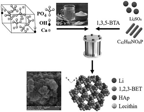
For the first time Ca10(PO4)6(OH)2/Li-MOFs were synthesised as dental resin nanocomposites with hydrothermal approach.
Glycyrrhiza glabra (Liquorice) root juice acts not only as green capping agent but also act as reducing agent.
Li-BioMOFsasa suitable substrate improve the hydroxyapatite mechanical properties.
Li-BioMOFssubstrates for Ca10(PO4)6(OH)2 nanostructures were synthesised in the presence of lecithin as bio stabiliser.
Highlight
Introduction
In the recent decades, nanostructures with a high potential in different domains have found application in medicine [Citation1], optoelectronic devices [Citation2], biological detection [Citation3,Citation4], drug delivery[Citation5] [], biotechnology and biophysics[Citation7] [Citation8], and dental nanocomposites [Citation9,Citation10]. Nanomaterials such as hydroxyapatites (HAps), Ca compounds, SiO2/TiO2, poly biphenyl [Citation11], and Ag nanocrystals are the main mineral components found in the bones have can have potential clinical applications due to their excellent biocompatible bioactive properties [Citation12] and osteoconductivity [Citation13]. Nano-hydroxyapatite with the chemical formula of Ca10(PO4)6(OH)2is a substance rich of calcium and the major mineral material of bones and teeth, and serves as the main source of calcium [Citation14–16]. In spite of many uses and advantages of HA, it has weaknesses in its mechanical properties, including breaking strength and fracture toughness [Citation14,Citation17,Citation18]. There are many approaches such as reinforcing phases, added nanocomposites, and dense ceramic material are the best cases which can be used to improve its mechanicalproperties atbiomedical applications [Citation19–21]. HAp has a broad range of application in different fields, such as in tissue engineering [Citation22,Citation23], dentistry [Citation24], fluorescent lamps [Citation25], development of fuel cells [Citation26], and orthopaedic implants for bone replacement [Citation27,Citation28]. Based on nanotechnology, due to an increased surface-to-volume ratio in nanoparticles, nano-hybrid filling acts as a novel bioactive reinforcing filler with excellent bioactivity [Citation29], biocompatibility [Citation30], good wear resistance, decreased shrinkage, and unique mechanical properties [Citation31]. Nano-HAp structures have been synthesized via various routes such as microwave-assisted synthesis [Citation32], solvothermal [Citation33], chemical precipitation [Citation34], emulsion method [Citation35], hydrolysis method [Citation36], sol-gel method [Citation37], and hydrothermal method [Citation38]. Recently, nano-HAps have been synthesised with different properties shown in . The hydrothermal method is a safe, cost-effective, mild, simple, practical [Citation39], and environmentally friendly method compared to other methods that can be adopted to produce HAp nanocrystals. Recently, different plants extract as green capping agent and reductant have been widely used in the preparation of the nanostructures [Citation40]. Glycyrrhiza glabra belongs to the Fabaceae family that has different phytocompounds such as glycyrrhizin, 18β‐glycyrrhetinic acid, glabrins, and isoflavones [Citation41]. Various extracts of this plant have a wide range of biological properties such as antibacterial, anti-inflammatory, antiviral, antidiabetic, and antioxidant [Citation42]. Due to the more extensive applications of Glycyrrhiza glabra in green synthesis, in this study, NHA was prepared with Glycyrrhiza glabra (liquorice) root juice through hydrothermal reaction for the first time, in which Glycyrrhiza glabra root juice acted as a crosslinking and auxiliary linker agent and a reductant compound and capping agent with high steric hindrance to produce NHA and Li-BioMOFs as a suitable and novel substrate. Glycyrrhizin glabrais one of the most important indigenous herbs in Iran, the main ingredient of which, i.e. glycyrrhizic acid (C42H62O16), is shown in . Thesynthesis of HAp nanoparticles was characterised by both mechanical and chemical properties with infra-red spectroscopy (FT-IR), ultraviolet spectroscopy (UV-vis), X-ray diffraction (XRD), scanning electron microscopy (SEM), and transmission electron microscopy (TEM) images.
Figure 1. Proposed chemical structure of Glycyrrhizinc acid (liquorice) root juice with HAp (a), experimental set up acquired the extraction of Glycyrrhiza glarba root juice (b).
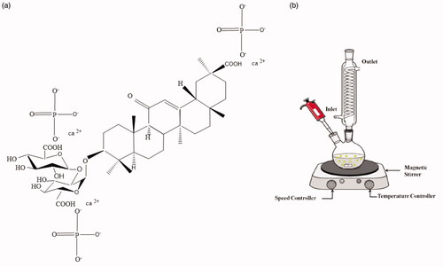
Table 1. Summary of studies with different properties in recent years.
Experimental procedure
Materials and methods
All of the material, including NaOH, CaCo3 (calcium carbonate, ≥99.0%), H2PO4 powder (96.986 g/mol Merck, reagent-grade), Li2SO4 (lithium sulphate, 99%, Sigma-Aldrich), cetyltrimethylammonium bromide (CTAB, Molar mass: 364.45 g/mol, ≥99.0%, Sigma-Aldrich), 1,3,5-benzenetricarboxylic acid (98%, Sigma-Aldrich), and lecithin as a bio emulsifier were used and received without further purification, purchased from Merck (Darmstadt, Germany). Also, deionised water was provided in the laboratory. The initial process of recrystallization yielded a yellow solution indicating the presence of impurities. Finally, a colourless solution was obtained indicating the purity of the material. XRD as a powerful analysis can be performed to examine nanomaterials’ crystallography. The XRD patterns of the products were recorded with a Rigaku D-max C III, X-ray diffractometer using Ni-filtered Cu-Ka radiation. To examine the morphological properties and particle size distribution, SEM images were obtained with Philips XL-30ESEM equipped with an energy dispersive X-ray spectroscopy (EDX) under the acceleration voltage of 100 kv. TEM images were obtained on a Philips EM208S with an accelerating voltage of 100 kV. The Fourier-transform infra-red spectroscopy (FT-IR spectra) were recorded by a Shimadzu Varian 4300 spectrophotometer in KBr pellets in the range of 400–4000 cm−1. Atomic force microscopy (AFM) images were obtained with a Nano wizard II JPK Made (Germany).
Preparation of Glycyrrhiza glabra (liquorice) root juice extract
Since the root material of liquorice dissolves in water, the roots should be washed very quickly with running water. After cleaning, the skin of the roots should be separated and then removed. The pieces were cut and dried for 10–15 cm. Then, the herbal dried roots were ground and the prepared powder was passed through a sieve with a specified mesh and extracted with water and ethanol (50 °C) for 6 h. The resulting solution was passed several times through a round-bottom double-neck flask to complete the extraction procedure. displays the experimental set-up for the extraction of Glycyrrhiza glabra root juice.
Preparation of nano-hydroxyapatite (nano-HAp)
In a typical method, 0.4 g of CaCo3 was dissolved in 10 ml of distilled water; then, the pH of the prepared solution was adjusted to 7.5–8 using freshly prepared 1 M NaOH solution. The solution was placed on a heater for 120 min at 50 °C under constant stirring at 400 rpm. Then, 5 ml of Glycyrrhiza glabra root juice was extracted and 0.5 g of H2PO4 powder (dissolved in 10 ml of distilled water) was added to the reaction mixture and placed in the oven for 2 days at room temperature. The products were eventually collected by filter paper, washed with ethanol, and dried at room temperature for 48 h.
Preparation of Ca10(PO4)6(OH)2/Li-BioMOFs
Initially, 90 mg of Li2SO4 powder was dissolved in 20 ml of distilled water. Then, 0.05 g of CTAB was dissolved in 5 ml of 1:2 deionised water, and ethanol was gradually mixed with this solution and stirred at 400 rpm and 50 °C until complete dissolution. Subsequently, 1 ml of lecithin 10% was poured dropwise into the reaction mixture for 30 min on a shaker. Next, 0.05 g of 1,3,5-benzenetricarboxylic acid was added to the above solution. Then, the reaction mixture was placed in an oven and heated for 12 h at 70 °C. Finally, the synthesis materials were collected, washed with distilled water, and dried at 80 °C for 24 h. To prepare the Ca10(PO4)6(OH)2/Li-BioMOFs, 0.012 g of as-synthesized nano-HAp was added to a constant value of Li-BioMOFs as 0.01 g, 0.03 g, and 0.05 g, according to . The final products were characterized with FT-IR, UV-vis, XRD, SEM, TEM, and AFM.
Table 2. Reaction conditions for the preparation of Ca10(PO4)6(OH)2/Li-BioMOFs nanostructure.
Mechanical testing
Flexural strength tests were performed using the universal test machine at 5 mm/min crosshead speed. The flexural strengths of the nanocomposites were calculated by the following equation.
(1)
(1)
where σ (MPa) is flexural strength, F (N) is flexural load, L (mm) is span length, b (mm) is the width of the specimen, and d (mm) is the thickness of the specimen. To measure the strength tests, the stainless steel cylindrical moulds with a diameter of 4 mm and height of 6 mm were placed on a glass slide and then overfilled with the HAp nanocomposites; then, another glass slide was placed on the top of nanocomposites to compress the mould. All of the compressive strength tests were then performed with the universal testing machine at a cross-head speed of 1 mm min−1.
Results and discussion
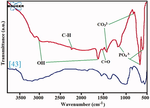
The FT-IR spectroscopy of the HAp nanocomposites was performed in the range of 400–4000 cm−1 and the results are illustrated in and compared with natural polymers nanocomposites [Citation43].The absorption bands in the regions of 1630 cm−1 and 2950 cm−1 are related to OH- stretching vibration in HAp structures. The presence of absorption peaks at 560-600 cm−1 and 650-1300 cm−1 is associated with PO4 3- agents, justifying the presence of an HAp structure. The stretching band of P-OH appears at 3300 cm−1 and the absorption of C = O is shown at 1636 cm−1. The absorption peaks at 835−1 and 1465 cm−1 can be attributed to the CO32- group.
Figure 2. The FT-IR spectroscopy of the HAp nanostructures in range of 400–4000 cm−1.
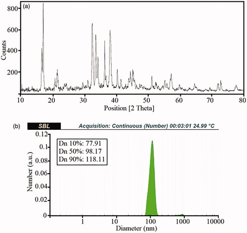
To characterise the phases, the crystallography and the examination of the crystallite size of the Ca10(PO4)6(OH)2/Li-BioMOFs, XRD pattern analysis are shown in . According to the X-ray pattern of HAp phases’ nano-crystals[Citation44], the presence of HAp phases’ nano-crystals on the substrate Li-BioMOFs creates new peaks that could be due to the nanoparticles trapped in the network structure of the BioMOFs. The size distribution and the mean diameter of the crystallites, as well as the relationship between the wavelength of the X-ray beam and the distance between each set of atomic planes of the crystal lattice, were calculated at about 150 nm from the XRD peaks with the Debye-Scherrer equation [Citation45] (EquationEquation 2(2)
(2) ).
(2)
(2)
where D is the mean crystallites size, λ is the X-ray wavelength (1.54 Ao), β is the broadening of the line measured at half its maximum intensity (in radius), θ is the diffraction angle from Bragg planes, and k is the shape factor. Dynamic light scattering (DLS) was adopted as a technique for measuring the size and intensity of particles, typically in the sub-micron and nanoscale region. The size of the final products was calculated from the translational diffusion coefficient by using the Stokes-Einstein equation (EquationEq. 3
(3)
(3) ).
(3)
(3)
where d(H), D, k, T, and η denote the hydrodynamic diameter, translational diffusion coefficient, Boltzmann constant, absolute temperature, and viscosity, respectively. The diameter of the particles which can be measured with DLS is a value displays how a particle diffuses within a fluid; therefore, it is referred to the hydrodynamic diameter. The DLS plot related to Sample 1 is depicted in . The average approximate size of the nanoparticles was ∼77–120 nanometres. The results show that with increasing the reaction temperature, the agglomeration of the active surface of the nanoparticles took place, that can be attributed to the higher nucleation and growth processes.
Figure 3. The XRD patterns (a) and DLS diagram of theCa10(PO4)6(OH)2/Li-BioMOFs nanostructures related to sample 1 (b).
SEM was used to investigate the surface properties as well as the morphological and particle size distribution of the nanostructures. The SEM images of the final samples prepared via the hydrothermal method at 150, 180, and 200 °C at 4 h are illustrated in .
Figure 4. The SEM images of the Ca10(PO4)6(OH)2/Li-BioMOFs nanostructures prepared via hydrothermal method in condition of 150, 180 and 200 °C at 4 h (a–c) and SEM image of sample with co-precipitation method (d).
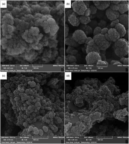
The as-synthesisedCa10(PO4)6(OH)2/Li-BioMOFs samples from 150 to 200 °C showed shapes as well as morphological and size distributions. The nanostructures as-synthesized with the hydrothermal method at 150 °C after 4 h had more uniform size and shape distribution. The results showed that at lower temperatures, such as 150 and 180 °C, since nucleation and growth processes were under control, enough energy to create spherical and separate nanoparticles was available. Based on SEM images, upon increasing the reaction temperature to 200 °C, decentralized clusters and the agglomeration zone are created, which can be due to the increased surface area-to-volume ratio. In order to examine the effect of the hydrothermal method in the synthesis of the Ca10(PO4)6(OH)2/Li-BioMOFs nanoparticles, a sample was tested with the co-precipitation method. The SEM image in shows a large particles size and amorphous structure synthesized by the co-precipitation method; therefore, the method can have a significant impact on the formation of nanoparticles.
According to the SEM images and DLS analysis, the formation of nano-sized Ca10(PO4)6(OH)2/Li-BioMOFs structures with the least agglomeration is related to the sample at 150 °C after 4 h with the hydrothermal method. To better understand the morphological and particle distribution and particle shape, Sample 1 was investigated by TEM in . The particles have a spherical shape, and their distribution is uniform. TEM results are in good agreement with SEM image results and also display the formed structures with a uniform distribution. The roughness, the elastic modulus of the interface, and the surface morphology of the samples with a scale size ranging from microns to sub-nanometres were characterized by AFM at the 3 D and 2 D scales in .
Figure 5. TEM image (a) and AFM with the 3 D scale of Ca10(PO4)6(OH)2/Li-BioMOFs nanostructure related to sample 1 (b).
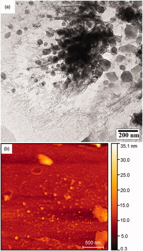
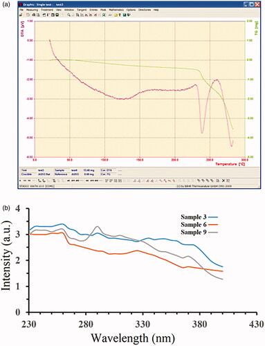
Based on the AFM analysis, the nanoparticles have spherical-like and homogenous structures. By comparing the surface roughness of the samples, it was found that some large particles and agglomerates existed in some places, and this can be attributed to the very active surface of the nanoparticles. To evaluate the thermal stability and understand the thermogravimetric analysis, in which the mass of the samples is measured over time as the temperature changes, the TGA diagram of the Ca10(PO4)6(OH)2/Li-BioMOFs nanoparticles related to Sample 1 is illustrated in . The TGA/DTA analysis curve reveals the one-step degradation stages for the Ca10(PO4)6(OH)2/Li-BioMOFs nanoparticles. The decomposition temperatures appear at ∼238 °C. This could be due to the thermal de-polymerization of the HAp structures. Finally, the rest of the structure up to 265 °C is destroyed completely. The good temperature stability of the HA nanostructures is due to the creation of a larger surface-to-volume ratio and, consequently, the presence of pores to increase the resistance of inter-molecular bonds. Also, the nanoparticles trapped in the network of BioMOFs as a substrate structure yield greater thermal stability. The optical properties of the Ca10(PO4)6(OH)2/Li-BioMOFs structures were investigated by UV–vis spectroscopy. The UV-vis spectra of Samples 3, 6, and 9 in distilled water as a solvent at room temperature are displayed in .The UV-vis spectra consist of one peak at ∼290.5 nm related to Sample 9 that can be attributed to a high level of transition in HAp crystallites. The results showed that by decreasing the reaction temperature from 200 to 150 °C, a blue shift is observed at the wavelength of 245 nm. This blue shift of the Ca10(PO4)6(OH)2/Li-BioMOFs structures related to Samples 6 and 3 can be due to the quantum size effect as well as the decreased band gap though the smaller particle size in quantum dot nanoparticles. Other samples showed no definite peak, indicating the absence of a crystalline structure.
Figure 6. TGA/DTA diagrams of the Ca10(PO4)6(OH)2/Li-BioMOFs nanostructure (a) and the UV-vis spectra of samples 3,6 and 9 at room temperature (b).
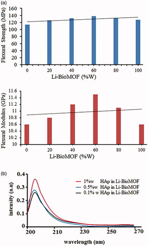
The mechanical properties of nano-HAp structures, such as tensile strength (MPa) and Young’s modulus (GPa), were improved by the addition of nano-bio Li/MOFs in the concentration range from 0 ppm (wt) up to 100 ppm (wt) (). Results indicated that the mechanical properties of nano-HAp structures in 60 ppm (wt) Li-BioMOF were increased by ∼132.5 MPa and 11.5 GPa for the flexural and Young’s modulus, respectively, compared with the composite without Li-BioMOF structures.The mechanical characteristics of nano-HAp structures depend on intermolecular Li-BioMOF structures with porous and unique properties, creating a widespread network of coherence in the final products. The existence of Li-BioMOF structures >60 ppm (wt) causes the loss of flexural and Young’s modulus due to a collapse in the network of the metal organic framework structure. To determine the optical properties and absorption, different concentrations of HAp nanostructures such as 1, 0.5, and 0.1% w were added to Li-BioMOF structures. Based on the results, in general, adding HAp nanostructures to Li-BioMOF structures reduced network defects in the structures, and blue shift occurred. The UV-vis spectra of different concentrations of HAp nanostructures such as 1, 0.5, and 0.1% w added to Li-BioMOF structures are demonstrated in .
Figure 7. Mechanical properties of the HAp nanostructures with different concentration of the Li-BioMOF flexural strength and flexural modulus (a) and the UV-vis spectra of HAp nanostructures concentrations such as 1%w, 0.5%w and 0.1%w added to Li-BioMOF (b).
Conclusion
In this study, for the first time, NHA structures were synthesized with Glycyrrhiza glabra (liquorice) root juice which acted not only as a green capping agent, but also as a reducing agent in reaction. It was observed that the mechanical properties of HAp structures are improved with adding Li-BioMOF structures that are as a class of biocompounds consisting of metal ions or clusters coordinated to green organic ligands to form one-, two-, or three-dimensional structures. The tensile strength (MPa) and Young’s modulus (GPa) of nanocrystalline HAP were significantly improved by the addition of 60 wt% of Li-BioMOF structures. The Li-BioMOFs substrates for Ca10(PO4)6(OH)2 nanostructures were synthesized in the presence of lecithin as a bio-stabilizer. Results showed that Li-BioMOFs acts as a suitable substrate and improves the HA mechanical properties. The processed nanocomposites were characterized by XRD, SEM, TEM, AFM, DLS, Uv-vis, and FT-IR. Based on the findings, at lower temperatures in the hydrothermal method, such as 150 and 180 °C, the nucleation and growth processes were under control; therefore, Sample 1 was selected as the optimum sample in terms of size and uniformity distribution.
Acknowledgements
Authors are grateful to council of Pharmaceutics Research Center, Institute of Neuropharmacology, Kerman University of Medical Sciences, Kerman, Iran.
Disclosure statement
No potential conflict of interest was reported by the author(s).
References
- Zamani M, Prabhakaran MP, Ramakrishna S. Advances in drug delivery via electrospun and electrosprayed nanomaterials. Int J Nanomedicine. 2013;8:2997–3017.
- Suárez PL, García-Cortés M, Fernández-Argüelles MT, et al. Functionalized phosphorescent nanoparticles in (bio)chemical sensing and imaging – a review. Anal Chim Acta. 2019;1046:16–31.
- Alivisatos P. The use of nanocrystals in biological detection. Nat Biotechnol. 2004;22(1):47–52.
- Yang W, Thordarson P, Gooding JJ, et al. Carbon nanotubes for biological and biomedical applications. Nanotechnology. 2007;18(41):412001.
- Zishan M. AN OVERVIEW OF: VESICULAR DRUG DELIVERY SYSTEM. WJPPS. 2017;:546–560. doi:10.20959/wjpps20175-9192.
- Varner SE, deJuan Jr E, Shelley T, Barnes AC, Humayun M, inventors; Johns Hopkins University, assignee. Devices for intraocular drug delivery. United States patent US 8,096,972. 2012 Jan 17.
- Dunford HB. Peroxidases and catalases: biochemistry, biophysics, biotechnology and physiology. John Wiley & Sons; 2010 Mar 15.
- Cesàro A, Bellich B, Borgogna M. Biophysical functionality in polysaccharides: From Lego-blocks to nano-particles. Eur Biophys J. 2012;41(4):379–395.
- Sarosi C, Biris AR, Antoniac A, et al. The nanofiller effect on properties of experimental graphene dental nanocomposites. j Adhes Sci Technol. 2016;30(16):1779–1794.
- Makvandi P, Jamaledin R, Jabbari M, et al. Antibacterial quaternary ammonium compounds in dental materials: a systematic review. Dent Mater. 2018;34(6):851–867.
- Li Y, Bastakoti BP, Imura M, et al. Synthesis of mesoporous TiO2/SiO2 hybrid films as an efficient photocatalyst by polymeric micelle assembly. Chemistry. 2014;20(20):6027–6032.
- Zhang X-F, Liu Z-G, Shen W, et al. Silver nanoparticles: synthesis, characterization, properties, applications, and therapeutic approaches. IJMS. 2016;17(9):1534.
- Ullah I, Li W, Lei S, et al. Simultaneous co-substitution of Sr2+/Fe3+ in hydroxyapatite nanoparticles for potential biomedical applications. Ceram Int. 2018;44(17):21338–21348.
- Zhao X-Y, Zhu Y-J, Qi C, et al. Hierarchical hollow hydroxyapatite microspheres: microwave-assisted rapid synthesis by using pyridoxal-5'-phosphate as a phosphorus source and application in drug delivery. Chem Asian J. 2013;8(6):1313–1320.
- Sarkar C, Chowdhuri AR, Kumar A, et al. One pot synthesis of carbon dots decorated carboxymethyl cellulose- hydroxyapatite nanocomposite for drug delivery, tissue engineering and Fe3+ ion sensing. Carbohydr Polym. 2018;181:710–718.
- Li M, Wang Y, Liu Q, et al. In situ synthesis and biocompatibility of nano hydroxyapatite on pristine and chitosan functionalized graphene oxide. J Mater Chem B. 2013;1(4):475–484.
- Thampi VA, et al. Hydroxyapatite, alumina/zirconia, and nanobioactive glass cement for tooth-restoring applications. Ceram Int. 2014;40(9):14355–14365.
- Mondal S, Hoang G, Manivasagan P, et al. Rapid microwave-assisted synthesis of gold loaded hydroxyapatite collagen nano-bio materials for drug delivery and tissue engineering application. Ceram Int. 2019;45(3):2977–2988.
- Niinomi M. Mechanical properties of biomedical titanium alloys. Mater Sci Eng A. 1998;243(1-2):231–236.
- Niinomi M. Mechanical biocompatibilities of titanium alloys for biomedical applications. J Mech Behav Biomed Mater. 2008;1(1):30–42.
- Baradaran S, Moghaddam E, Basirun WJ, et al. Mechanical properties and biomedical applications of a nanotube hydroxyapatite-reduced graphene oxide composite. Carbon. 2014;69:32–45.
- Ripamonti U, Duneas N. Tissue engineering of bone by osteoinductive biomaterials. MRS Bull. 1996;21(11):36–39.
- Gentile P, Wilcock C, Miller C, et al. Process optimisation to control the physico-chemical characteristics of biomimetic nanoscale hydroxyapatites prepared using wet chemical precipitation. Materials. 2015;8(5):2297–2310.
- Basar B, Tezcaner A, Keskin D, et al. Improvements in microstructural, mechanical, and biocompatibility properties of nano-sized hydroxyapatites doped with yttrium and fluoride. Ceram Int. 2010;36(5):1633–1643.
- Xue D, Zheng Q, Zong C, et al. Osteochondral repair using porouspoly(lactide-co-glycolide)/nano-hydroxyapatite hybrid scaffolds with undifferentiated mesenchymal stem cells in a rat model. J Biomed Mater Res A. 2010;94(1):259–270.
- Laghzizil A, Elherch N, Bouhaouss A, et al. Electrical behavior of hydroxyapatites M10 (PO4) 6 (OH) 2 (M = Ca, Pb, Ba). Mater Res Bull. 2001;36(5-6):953–962.
- Shepherd JH, Shepherd DV, Best SM. Substituted hydroxyapatites for bone repair. J Mater Sci Mater Med. 2012;23(10):2335–2347.
- Ratnayake JT, Mucalo M, Dias GJ. Substituted hydroxyapatites for bone regeneration: a review of current trends. J Biomed Mater Res B Appl Biomater. 2017;105(5):1285–1299.
- Siddiqui N, Pramanik K. Effects of micro and nano β‐TCP fillers in freeze‐gelled chitosan scaffolds for bone tissue engineering. J. Appl. Polym. Sci. 2014;131(21): 41025 (1-10).
- Wang H, Li Y, Zuo Y, et al. Biocompatibility and osteogenesis of biomimetic nano-hydroxyapatite/polyamide composite scaffolds for bone tissue engineering. Biomaterials. 2007;28(22):3338–3348.
- Zhou H, Lee J. Nanoscale hydroxyapatite particles for bone tissue engineering. Acta Biomater. 2011;7(7):2769–2781.
- Wang K-W, Zhu Y-J, Chen F, et al. Microwave-assisted synthesis of hydroxyapatite hollow microspheres in aqueous solution. Mater Lett. 2011;65(15–16):2361–2363.
- Chen F, Zhu Y-J, Wang K-W, et al. Surfactant-free solvothermal synthesis of hydroxyapatite nanowire/nanotube ordered arrays with biomimetic structures. CrystEngComm. 2011;13(6):1858–1863.
- Monmaturapoj NJ. Nano-size hydroxyapatite powders preparation by wet-chemical precipitation route. J Mater Miner.2017;18(1):15-20,
- Perez RA, Del Valle S, Altankov G, et al. Porous hydroxyapatite and gelatin/hydroxyapatite microspheres obtained by calcium phosphate cement emulsion. J Biomed Mater Res B Appl Biomater. 2011;97(1):156–166.
- Venkatesan J, Qian ZJ, Ryu BMi, et al. A comparative study of thermal calcination and an alkaline hydrolysis method in the isolation of hydroxyapatite from Thunnus obesus bone. Biomed Mater. 2011;6(3):035003.
- Fathi M, Hanifi A. Evaluation and characterization of nanostructure hydroxyapatite powder prepared by simple sol–gel method. Mater Lett. 2007;61(18):3978–3983.
- Hui P, Meena SL, Singh G, et al. Synthesis of hydroxyapatite bio-ceramic powder by hydrothermal method. JMMCE. 2010;09(08):683–692.
- Lai W, Chen C, Ren X, et al. Hydrothermal fabrication of porous hollow hydroxyapatite microspheres for a drug delivery system. Mater Sci Eng C Mater Biol Appl. 2016;62:166–172.
- Tavakoli F, Salavati-Niasari M, Ghanbari D, et al. Application of glucose as a green capping agent and reductant to fabricate CuI micro/nanostructures. Mater Res Bull. 2014;49:14–20.
- Kavitha KS, Baker S, Rakshith D. Kavitha HU, Yashwantha Rao HC, Harini BP. Satish S. Plants as Green Source towards Synthesis of Nanoparticles. Int Res J Biol Sci. 2013;2(6):66–76.
- Siracusa L, Saija A, Cristani M, et al. Phytocomplexes from liquorice (Glycyrrhiza glabra L.) leaves-chemical characterization and evaluation of their antioxidant, anti-genotoxic and anti-inflammatory activity. Fitoterapia. 2011;82(4):546–556.
- Chung J-H, Kim YK, Kim K-H, et al. Synthesis, characterization, biocompatibility of hydroxyapatite-natural polymers nanocomposites for dentistry applications. Artif Cells Nanomed Biotechnol. 2016;44(1):277–284.
- Liu R, Lal RJ. Synthetic apatite nanoparticles as a phosphorus fertilizer for soybean (Glycine max). Sci Rep. 2014;4(2):5686.
- Abbasi S, Golestani-Fard F, Mirhosseini SMM, et al. Effect of electrolyte concentration on microstructure and properties of micro arc oxidized hydroxyapatite/titania nanostructured composite. Mater Sci Eng C Mater Biol Appl. 2013;33(5):2555–2561.
- Rusu VM, Ng C-H, Wilke M, et al. Size-controlled hydroxyapatite nanoparticles as self-organized organic-inorganic composite materials. Biomaterials. 2005;26(26):5414–5426.
- Tampieri A, D'Alessandro T, Sandri M, et al. Intrinsic magnetism and hyperthermia in bioactive Fe-doped hydroxyapatite. Acta Biomater. 2012;8(2):843–851.
- Gopi D, Ramya S, Rajeswari D, et al. Strontium, cerium co-substituted hydroxyapatite nanoparticles: synthesis, characterization, antibacterial activity towards prokaryotic strains and in vitro studies. Colloids Surf, A. 2014;451:172–180.
- Talaei H, Fallah-Mehrjardi M, Hakimi F. Polyethylene glycol-(N-methylimidazolium) hydroxide-grafted γ-Fe2O3@HAp: a novel nanomagnetic recyclable basic phase-transfer catalyst for the synthesis of tetrahydrobenzopyran derivatives in aqueous media. J Chin Chem Soc. 2018;65(5):523–530.
- Priyadarshini Bs. Preparation and characterization of sol-gel derived Ce4+ doped hydroxyapatite and its in vitro biological evaluations for orthopedic applications. Mater Des. 2017;119:446–455.