
 ?Mathematical formulae have been encoded as MathML and are displayed in this HTML version using MathJax in order to improve their display. Uncheck the box to turn MathJax off. This feature requires Javascript. Click on a formula to zoom.
Abstract
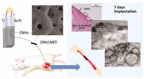
Direct contact between bone and implant materials is required for dental implants. Titanium is used for the implant material owing to its mechanical and biological properties. The anodisation as the surface treatment was employed to enhance osteogenesis around titanium. Moreover, carbon nanohorn (CNH), a type of nanometer-sized carbon material, was reported to promote the bone formation. Thus, it is expected that if the surface of anodised Ti (AnTi) is modified with CNHs, Ti-bone contact would be enhanced. In this study, the Ti surface was modified with CNHs by electrophoresis and obtained anodised titanium coated with CNHs (CNH/AnTi). In vitro, CNH/AnTi attracted osteoblastic cells more than AnTi, thereby the proliferation of osteoblastic cell was enhanced by CNH/AnTi more than by AnTi. In vivo, at 7 and 28 days after implantation of CNH/AnTi or AnTi into the rat femur, more aggressive bone formation was observed on the surface of CNH/AnTi than on AnTi. More importantly, the area where newly formed bone tissue directly attached to CNH/AnTi was significantly larger than that for AnTi, suggesting that “contact osteogenesis” was accelerated on CNH/AnTi during the early post-implantation period. CNH/AnTi would be advantageous especially for the early stages of bone regeneration after surgery.
Graphical Abstract
Introduction
Titanium (Ti) is the most commonly-used biomaterial for dental implants because of its excellent mechanical and biological properties [Citation1], where surface modifications are useful approaches to enhance the biological properties of Ti. Anodisation is employed to increase the Ti surface roughness by forming Ti oxide layer (AnTi), thereby improving the wettability and biocompatibility of the Ti surface [Citation2,Citation3]. After the anodisation, further modifications are often applied to improve biocompatibility or accelerate biological responses such as osteoblast adhesion, proliferation, and bone responses [Citation4,Citation5]. Several researchers reported the favourable effect of micro/nano surface for bone regeneration. Kubo et al. reported that in a rat femur model the strength of bone–titanium integration was more than three times greater for the AnTi implants with micropits and 300-nm nanonodules than the AnTi implants with micropits alone [Citation6]. Cheol-Min et al. reported that micro/nano-porous surface showed considerably enhanced hydrophilicity and in vitro biocompatibility compared to the dense surface and even the micro-porous and nano-porous surfaces [Citation7]. Therefore, coating nanomaterials on the microstructure of AnTi was expected to become an effective implant material.
Nanomaterials such as carbon nanohorns (CNHs), nanotubes (CNTs), and graphenes are promising nanomaterials for applications in biomaterials because of their favourable cytocompatibility in addition to the unique chemical and physical properties [Citation8–19]. Furthermore, the electrical conductivity [Citation20–22] and the typical surface structure [Citation23–29] of CNMs are expected to be applied to bone regeneration. For example, CNT-coated collagen sponges facilitate excellent adhesion and differentiation of osteoblasts due to the unique network-like structure of CNTs [Citation23–26]. On the other hand, the impurities (e.g. metal catalysts and amorphous carbons) and the high aspect ratio of CNTs might lead to concerns about their safety for clinical uses [Citation30,Citation31]. CNHs which is a spherical assembly of thousands of single walled graphene-like nanotubules having the assembly diameter around 100 nm [Citation32] have attracted interest in biomaterial and biomedical fields because they have low toxicity [Citation33–36] and large inner nanospaces where drugs can be loaded [Citation9,Citation13,Citation33]. We reported that a CNH coated polytetrafluoroethylene membrane without growth factor loading promoted bone formation in the early stages, i.e. within 2 weeks after surgery [Citation35]. One of the possible mechanisms of bone formation using carbon nanomaterials was discussed in relation to macrophages. In the case of CNHs, when macrophages engulf the CNHs, they accelerate the differentiation of mesenchymal stem cells into osteoblasts via Oncostatin M release [Citation36]. Thus it is expected that if the CNHs were deposited on the surface of implant material such as Ti, they should effectively promote the osteogenesis. In this study, to take advantage of the above features of CNHs for dental implant therapy, the AnTi surface was coated with CNHs (CNH/AnTi) by electrophoretic deposition and show that it was effective in the bone regeneration in vivo. The mechanism of the bone generation enhancement by CNH/AnTi has been also discussed by using results obtained from the histological observation of CNH/AnTi on the bone regeneration sites and from the osteoblastic cell proliferation studies in vitro.
Materials and methods
Specimen preparation
Anodising titanium
The titanium was anodised by our previously published method [Citation37]. The Ti plates (99.5%; Nilaco, Tokyo, Japan) were cut into discs (9.0 mm in diameter) and the Ti wire (99.5%, 1.0 mm in diameter; Nilaco) was cut into 5.0 mm lengths. Subsequently, the cut Ti plates and wires were ground incrementally with #600 to #1500 grit waterproof silicon carbide abrasive paper and then washed with ethanol and distilled water in an ultrasonic cleaner for 5 min (). The Ti disc was then connected to a Ti wire by laser welding, whereupon the Ti wires were shielded with a clear silicone nail polish (Dear Laura, Osaka, Japan) to leave only the disc exposed. The prepared Ti disc/wire was connected to an anode, and a platinum mesh (0.1 mm in thickness) was connected to a cathode. An aqueous solution of 0.025 M DL-α-glycerophosphate disodium salt (>85%; Tokyo Chemical Industry, Tokyo, Japan) and 0.2 M calcium acetate (99%; Kanto Chemical, Tokyo, Japan) were used as the anodising electrolytes. Anodisation was carried out in constant current mode upon reaching the preset voltage using a DC power supply (PMC500-0.1A, Kikusui, Yokohama, Japan), where the current density was 30 mA/cm2 and the anodic voltage was 320 V. During anodic oxidation, the electrolyte was maintained at room temperature (25 °C). Upon reaching 320 V, constant voltage was maintained for 1 min.
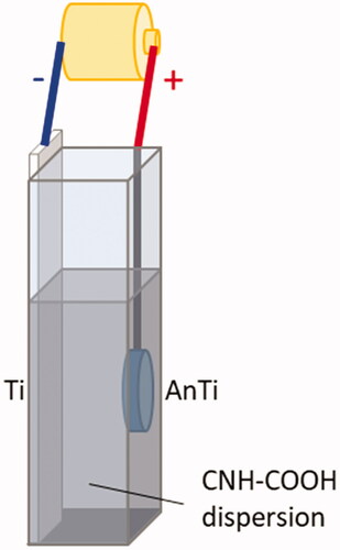
Figure 1. Schematic representation of the electrodeposition process.
Electrodeposition of CNHs on anodised Ti
The single-walled CNHs were produced by CO2 laser ablation of graphite without a metal catalyst [Citation32], and the purity of the as-grown CNH was estimated at 95%. The CNHs were then oxidised and carboxylated to be CNH-COOH by our previously published method [Citation38] wherein, briefly, the CNH powder was dispersed in 30% (v/v) H2O2 (Wako, Osaka, Japan) at a concentration of 1 mg/mL assisted by 30 s of sonication in a brown vial, and then stirred at room temperature for 24 h. The solution was vacuum filtered and then washed with abundant water, whereupon the solution was dried to a powder at room temperature under vacuum for around 3 d. The CNH powder was dispersed in 99.9% ethanol at 250 μg/mL, 3 ml of which was transferred to a 1 cm cuvette. The anodised Ti (AnTi) was connected to an anode and the Ti was connected to a cathode, whereupon both electrodes were placed in the cuvette while maintaining an inter-electrode distance of 8.0 mm, as shown in . Then, DC voltages of 25,03,00,350 and 400 V were applied between the electrodes for 60, 120, 180, 240 s using a PMC500-0.1A power supply. The surface structure was then observed by scanning electron microscopy (SEM; S-400, Hitachi, Tokyo, Japan), and the CNH deposition area was measured by using the software Image-Pro Premier 9.1 (Nippon Rober, Media Cybernetics, Tokyo, Japan). Typical thicknesses of the deposited films were estimated by cross-sectional analysis using field emission (FE)-SEM (JIB-4600F, JEOL Ltd., Tokyo, Japan) after sputter coating with gold.
Cell culturing
Human osteoblastic osteosarcoma cell line (Saos2) [Citation39,Citation40] were suspended in Dulbecco’s modified Eagle’s medium (Sigma-Aldrich, St. Louis, MO) containing 10% fetal bovine serum (Biowest, Riverside, MS) and 1% penicillin/streptomycin (Thermo Fischer Scientific, Gibco, Waltham, MA) at 50 U/mL penicillin and 50 µg/mL streptomycin. The AnTi and CNH-deposited AnTi (CNH/AnTi) samples were placed in the wells of a 48-well plate, and 500 μL of the cell suspension at 1 × 10⁴ cells/mL was seeded on the scaffold in the wells and then incubated at 37 °C in a 5% CO2 atmosphere for 7 d.
After cell culture, we observed the cells on the specimens by SEM, where the samples were washed three times with phosphate-buffered saline and fixed with 2.5% glutaraldehyde. After dehydration through a graded ethanol series, they were dried using the critical point method and sputter coated with palladium-platinum for SEM observation.
After cell culture, 300 µL of the cell suspension containing 0.2% IGEPAL CA630 (Sigma-Aldrich, St. Louis, MO) was added to each sample. The samples were frozen, thawed, and then homogenised. The sample solution was added to 100 µL of 4 M NaCl, 0.1 M phosphate buffer (pH 7.4) and then centrifuged for DNA analysis. Picogreen (Thermo Fischer Scientific, Waltham, MA) was used to measure the DNA content via a fluorometer (Infinite F200 PRO, Tecan, Männedorf, Switzerland) with the excitation filter set at 356 nm and the emission filter at 458 nm. The alkaline phosphatase (ALP) activity was measured with a LabAssay kit (Wako) as described previously [Citation25]. The ALP activity was normalised to the DNA content, and the DNA content and ALP activity were determined in four samples.
Animal experiments
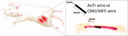
The animal experiment was carried out by our previously published method [Citation41]. Ti wire (99.5%, 1.0 mm in diameter, 5 mm in length; Nilaco. Tokyo, Japan) was anodised and electrodeposited with CNHs using the method above. Twenty-four male Wistar rats aged 10 weeks (body weight: 300–330 g) were used (n = 6 for each group). The rats were anesthetized with an isoflurane inhalation solution (Pfizer Inc., NY). Holes were drilled in the left femurs with a round dental bur 2.0 mm in diameter with a physiological saline external coolant. Then, AnTi or CNH/AnTi wires were inserted from the holes into the bone marrow in the femurs diagonally as shown in .
Figure 2. Schematic representation of the surgery.
Animal experiments were performed in accordance with the Guide for the Care and Use of Laboratory Animals [Approval No. Hokkaido University (14-0090)].
At 1 and 4 weeks after surgery, the rats were anaesthetized and perfused with 5% glutaraldehyde diluted in 0.1 M cacodylate buffer (pH 7.4) through the left cardiac ventricle. The femurs with implants were resected and immersed in 10% neutral buffered formaldehyde. The hard tissue was then decalcified with ethylenediaminetetraacetic acid, after which the implants were removed from the bone marrow as carefully as possible to maintain the interface between the tissue and specimens. The samples were then embedded in paraffin and sagittally sectioned to about 5 µm in thickness. The specimens were stained with haematoxylin and eosin, and placed under an optical microscope (AX-80, Olympus, Tokyo, Japan) to be examined for tissue responses such as osteogenesis around the implants.
After optical microscopic observation, some of the sample mounted on the glass slide was used for transmission electron microscopy (TEM) analysis. The TEM samples were prepared by the method previously reported [Citation42,Citation43]. The mounting agent was removed by xylene, whereupon a capsule filled with Epon resin was loaded on the sample. The glass slide was then removed from the polymerised block surface by heating, and ultrathin sections were obtained using an ultramicrotome (Leica, Wetzlar, Germany) with a diamond knife (DiATOME, PA). These ultrathin sections were examined by TEM (JEM1400 80 V, JEOL Ltd. Tokyo, Japan).
The bone contact ratio (BCR) [Citation44] was calculated to evaluate the osteoconductivity of CNH/AnTi. Histomorphometric analysis was performed using ImageJ software (National Institutes of Health, Bethesda, MD). The five sections were selected randomly and a total of twenty areas containing the implant and surrounding bone from each sample were assessed. The length of direct contact of the bone with CNH/AnTi was measured on the histological sections, and the BCR was calculated using
Statistical analysis was carried out using the Kruskal–Wallis H-test and Mann–Whitney U-test with Bonferroni correction.
Results and discussion
Preparation and structure of CNH/anti
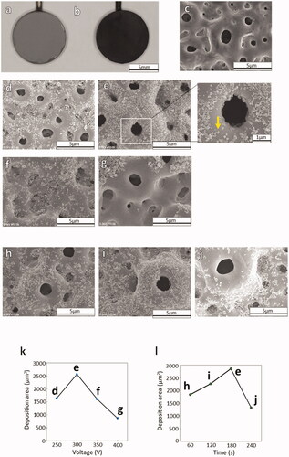
is the photographs after and before the electrodeposition of CNHs on the AnTi. After the electrodeposition of CNHs on AnTi (), the surface became black as shown in . To determine the optimal electrodeposition conditions, the applied voltage () and duration () were varied, and the optimal condition for homogeneous coverage of the AnTi surface () with CNHs was 300 V for 180 s (). In , one of the CNHs agglomerates are designated with a yellow arrow. At a lower voltage of 250 V, few CNHs were deposited on AnTi (), and higher voltages of 350 V () or 400 V () exhibited decreased coverage of CNHs on the AnTi surface. The CNHs did not fully cover the AnTi surface for shorter durations of 60 s () or 120 s (), while a longer duration of 240 s exhibited agglomerations of CNHs that formed clumps on the surface (). The graph of CNH deposition area showed that the amount of adhesion decreased with a peak at 300 V when the current was applied for 180 s (). At 300 V of applied voltage, the CNH deposition coverage on the AnTi surface was its largest at 180 s ().
Figure 3. Photographs of (a) bare AnTi and (b) CNH-deposited AnTi. SEM images of (c) bare ANTi and CNH/AnTi prepared by electrodeposition of CNHs for 180 s duration at DC voltages of (d) 250, (e) 300, (f) 350, and (g) 400 V. Yellow arrow: CNHs. SEM images of CNH/AnTi prepared at a DC voltage of 300 V for durations of (h) 60, (i) 120 and (j) 240 s. The graph of CNH deposition area for 180 s duration (k). The graph of CNH deposition area at 300 V of applied voltage (l).
The surfaces were observed under higher magnification with FE-SEM. The images of CNH/AnTi prepared with an applied voltage of 300 V for 180 s showed the CNHs depositing on the AnTi surface (). The CNHs are indicated with white arrowheads in . The thickness of the deposited CNHs on the AnTi was 0.2–0.5 µm (). Occasionally, CNHs were localised inside the micropores of AnTi (grey arrow in ). The pores of the AnTi were not filled, and neither the porosity nor the pore size was changed by the electrodeposition of CNHs as shown in and . The images of AnTi did not show such deposition on the surface ()
Figure 4. Cross-section FE-SEM images of (a) AnTi, (b) high-resolution image corresponding to the white box in (a), (c) CNH/AnTi prepared with an applied voltage of 300 V for 180 s, and (d) high-resolution image corresponding to the white box in (c). The voltage and duration time of anodisation were 300 V and 180 s, respectively. Labels indicate areas comprising anodised titanium porous layer (An); titanium layer (Ti); and vapour deposition gold layer (Au). White arrowhead: CNHs. Grey arrows: micropores of anodised titanium porous layers.
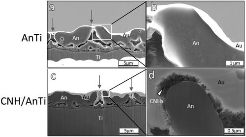
Sirivisoot et al. have reported that multiwalled CNTs were grown on AnTi by chemical vapour deposition at high temperature (700 °C) [Citation45], but this deposition method requires large equipment with highly-reactive gaseous materials. On the contrary, electrodeposition is more facile as it can be performed at room temperature with a small apparatus under an ambient atmosphere. Therefore, electrodeposition is considered a facile method for CNH deposition on AnTi.
Advantage of CNH/anti in osteogenesis in vitro
To investigate the advantages of CNH/AnTi in osteogenesis, the AnTi efficiently covered with CNHs by electrodeposition with an applied voltage of 300 V for 180 s were used for the in vitro and in vivo studies. Ti discs (9.0 mm in diameter) were used for in vitro study.
After osteoblast-like cell culturing, more cells were adhered on the CNH/AnTi () than on AnTi () at 1 d, and the cell filopodia stretched on the CNH/AnTi (, white arrowhead), while they were less seen on AnTi (, black arrowhead). The DNA content in the cells adhered on CNH/AnTi was significantly higher than that in cells on AnTi at 7 d () (p < .01). There was no significant difference between the samples in terms of ALP activity normalised to the DNA content () (p > .1).
Figure 5. SEM observations of osteoblast-like cells after 1 d of cell culture on (a) AnTi and (b) CNH/AnTi. (c) High resolution image of white box area in (a). Black arrowhead in (c); filopodia. (d) High resolution of white box area in (b). White arrowhead in (b); filopodia. (e) Cell DNA content on each sample at 7 d. (f) ALP activity normalised to cell DNA content on each sample at 7 d. n = 5, **p < .01.
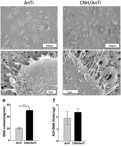
Several studies reported the effect of the nano and micro surface topography on the cells. Allahyari et al. reported that micron-scale surface disruption weakens cell − substrate interactions on stiff substrates [Citation46]. Shtansky et al. reported that the change of surface porosity and roughness may influence the adhesion, spreading, growth, and differentiation of osteogenic cells [Citation47]. Tay et al. have reported that nanoparticles can retard cell migration via increased adhesions [Citation48]. We have previously reported that the physical structure of a multiwalled CNT-coated surface could affect cell entrapment during the cell seeding [Citation24]. In this study, the pores of the AnTi were not filled, and neither the porosity nor the pore size was changed by the electrodeposition of CNHs. More filopodia were observed on CNH/AnTi compared on the AnTi. Therefore the nanostructure of the CNH on AnTi surface as a cell culturing substratum could improve cell adhesion and proliferation but did not have a remarkable effect on the differentiation.
Advantage of CNH/anti in osteogenesis in vivo
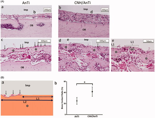
shows the optical micrographs of AnTi () and CNH/AnTi () wire (1.0 mm in diameter, 5 mm in length) in the bone marrow at 7 days after implantation. The AnTi and CNH/AnTi wires were picked out carefully after cutting the decalcified bones, and the location of the picked-out-wires are shown as “Imp”. Immature bone tissue was observed between the implant and the original bone tissue designated as OB at 7 d after surgery (). In the higher magnification images, many osteoblasts with a cuboidal shape (arrow in ) were observed aligned on the bone newly-formed on AnTi (). On the CNH/AnTi, the bone tissue directly attached to “Imp” in some parts (). This direct contact of the implant materials and the newly-generated bones indicates the “contact osteogenesis”, which occurs in the bone formation by the combination of recruitment and migration of osteogenic cells [Citation49]. Moreover, the bone-contact-ratio (BCR) defined as L1/L2 as shown in was estimated. BCR of CNH/AnTi was significantly higher (p < .05) than that of AnTi at 7 d ().
Figure 6. Bone regeneration by using AnTi and CNH/AnTi. A. Histological observations with an optical microscope at 7 d after surgery. (a,c) AnTi group showing (a) lower and (c) higher magnification images. (b,d,e) CNH/AnTi group showing (b) lower and (d) higher magnification images, and (e) highest-resolution image corresponding to the white box in (d). “Imp” indicates areas with removed AnTi or CNH/AnTi. OB: original bone. “*”: newly-formed bone. White arrowhead: black spots of CNHs. B. (a) Schematic representation of L1 and L2 for the estimation of the Bone Contact Ratio (BCR) estimated as the length ratio of L1/L2. L1 was the length where new bones directly contacted Ti. L2 was the length where fibrous tissue, fibroblast and osteoblast existed between the new bones and Ti. (b) BCR at 7 d after surgery for AnTi and CNH/AnTi. (n = 4, the five sections were selected randomly and a total of twenty areas in each sample were assessed. *p < .05).
The analogous tendency was observed even after 28 days of implantation as presented in . The optical microscopy observation in show the newly formed bone on AnTi (asterisk in ) and CNH/AnTi (asterisk in ). Many black particles thought to be CNHs were recognised on the bone in . For confirmation, the contact area between CNH/AnTi and bone was observed by TEM after the decalcification, cutting, and removal of AnTi wire (). The CNHs are indicated with white arrowheads in , which structure is similar to that of original CNHs presented in . shows that the newly-formed bones included amorphous layer (AL). According to the study done by Linder et al., the AL could be “20-nm-thick layer of proteoglycans” separating the bone tissue collagen from the Ti implant surface in rabbit tibiae [Citation50]. The AL is usually generated near the bones in the bone regeneration process. In , it is apparent that the CNHs attached to the newly-formed bones.
Figure 7. (a,b) Histological observations at 28 d after surgery showing (a) AnTi group and (b) CNH/AnTi group. Some black particles (white arrow head) were seen on bone surface. (c–e) TEM images of the tissue on the surface of CNH/AnTi showing (c) low magnification image and (d) high-resolution of the area of the white box in (c). (e) High-resolution of the area of the white box in (d). (f) TEM images of original CNHs. The area with removed AnTi or CNH/AnTi (Imp); newly-formed bone (*); CNHs (white arrowhead); osteocyte (OC); amorphous layer (AL) between the CNHs and the bone tissue collagen.
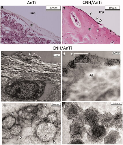
There were only a few macrophages that engulfed CNHs around the CNH/AnTi (Data not presented). As previously shown, the macrophages actively engulfed the CNHs when they were free in moving. Therefore, it may be estimated that CNH did not detach from CNH/AnTi, meaning that there were few free CNHs and most of CNHs were attached to the surface of AnTi.
These results suggest that acceleration of adhesion and proliferation of osteoblasts on the surface of CNH/AnTi induced the “contact osteogenesis” in the early period.
Conclusion
Herein, AnTi was successfully coated with CNHs via electrodeposition, and the CNH/AnTi exhibited favorable biocompatibility with bone. CNH/AnTi attracted osteoblastic cells more than AnTi, thereby the proliferation of osteoblastic cells was enhanced by CNH/AnTi more than by AnTi in vitro. Also in vivo, CNHs promoted bone formation in the early stages of bone healing. It was further noticed that the new bones directly attached to the CNH/AnTi, suggesting that CNH/AnTi accelerates the “contact osteogenesis” during the early post-implantation period. The implants which promote osteogenesis are expected to be more effective in elderly people and patients with bone metabolism such as diabetes. Thus, the CNHs/AnTi could be one of the next-generation surface treatments of implant and hopeful for the advancement of implant treatments. Our findings may be an important milestone and inspire the new design for therapeutic materials on bone regeneration using CNMs.
| Abbreviations | ||
| CNH | = | Carbon nanohorn |
| Ti | = | Titanium |
| AnTi | = | Anodised titanium |
| CNH/AnTi | = | CNH-deposited AnTi |
| CNT | = | Carbon nanotube |
| SEM | = | Scanning electron microscopy |
| FE | = | Field emission |
| Saos2 | = | Human osteoblastic osteosarcoma cell line |
| ALP | = | Alkaline phosphatase |
| TEM | = | Transmission |
Acknowledgements
Part of this work was conducted at Hokkaido University and supported by the “Nanotechnology Platform” Program of the Ministry of Education, Culture, Sports, Science and Technology (MEXT), Japan.
Disclosure statement
No potential competing interest was reported by the author(s).
Additional information
Funding
References
- Van Noort R. Titanium: the implant material of today. J Mater Sci. 1987;22(11):3801–3811.
- Sul YT, Johansson CB, Jeong Y, et al. Oxidized implants and their influence on the bone response. J Mater Sci Mater Med. 2001;12(10–12):1025–1031.
- Le Guehennec L, Lopez-Heredia MA, Enkel B, et al. Osteoblastic cell behaviour on different titanium implant surfaces. Acta Biomater. 2008;4(3):535–543.
- Bauer S, Schmuki P, von der Mark K, et al. Engineering biocompatible implant surfaces: part I: materials and surfaces. Prog Mater Sci. 2013;58(3):261–326.
- Wang X, Xu S, Zhou S, et al. Topological design and additive manufacturing of porous metals for bone Scaffolds and orthopaedic implants: a review. Biomaterials. 2016;83:127–141.
- Kubo K, Tsukimura N, Iwasa F, et al. Cellular behavior on TiO2 nanonodular structures in a micro-to-nanoscale hierarchy model. Biomaterials. 2009;30(29):5319–5329.
- Han CM, Kim HE, Koh YH. Creation of hierarchical micro/nano-porous TiO2 surface layer onto Ti implants for improved biocompatibility. Surf Coatings Technol. 2014;251:226–231.
- Marangon I, Ménard-Moyon C, Silva A. K a, et al. Synergic mechanisms of photothermal and photodynamic therapies mediated by photosensitizer/carbon nanotube complexes. Carbon N Y. 2016;97:110–123.
- Miyako E, Deguchi T, Nakajima Y, et al. Photothermic regulation of gene expression triggered by laser-induced carbon nanohorns. Proc Natl Acad Sci U S A. 2012;109(19):7523–7528.
- Girase B, Shah JS, Misra RDK. Cellular mechanics of modulated osteoblasts functions in graphene oxide reinforced elastomers. Adv Eng Mater. 2012;14(4):B101–111.
- Kruss S, Hilmer AJ, Zhang J, et al. Carbon nanotubes as optical biomedical sensors. Adv Drug Deliv Rev. 2013;65(15):1933–1950.
- Miyako E, Kono K, Yuba E, et al. Carbon nanotube-liposome supramolecular nanotrains for intelligent molecular-transport systems. Nat Commun. 2012;3:1226.
- Murakami T, Ajima K, Miyawaki J, et al. Drug-loaded carbon nanohorns: adsorption and release of dexamethasone in vitro. Mol Pharm. 2004;1(6):399–405.
- Wang J, Hu Z, Xu J, et al. Therapeutic applications of low-toxicity spherical nanocarbon materials. NPG Asia Mater. 2014;6(2):e84–e84.
- Yang K, Feng L, Shi X, et al. Nano-graphene in biomedicine: theranostic applications. Chem Soc Rev. 2013;42(2):530–547.
- Battigelli A, Ménard-Moyon C, Bianco A. Carbon nanomaterials as new tools for immunotherapeutic applications. J Mater Chem B. 2014;2(37):6144–6156.
- Bianco A, Cheng HM, Enoki T, et al. All in the graphene family – a recommended nomenclature for two-dimensional carbon materials. Carbon N Y. 2013;65:1–6.
- Orecchioni M, Cabizza R, Bianco A, et al. Graphene as cancer theranostic tool: progress and future challenges. Theranostics. 2015;5(7):710–723.
- Orecchioni M, Jasim DA, Pescatori M, et al. Molecular and genomic impact of large and small lateral dimension graphene oxide sheets on human immune cells from healthy donors. Adv Healthc Mater. 2016;5(2):276–287.
- Allahyari Z, Haghighipour N, Moztarzadeh F, et al. Optimization of electrical stimulation parameters for MG-63 cell proliferation on chitosan/functionalized multiwalled carbon nanotube films. RSC Adv. 2016;6(111):109902–109915.
- Nekounam H, Allahyari Z, Gholizadeh S, et al. Simple and robust fabrication and characterization of conductive carbonized nanofibers loaded with gold nanoparticles for bone tissue engineering applications. Mater Sci Eng C Mater Biol Appl. 2020;117:111226.
- Nekounam H, Gholizadeh S, Allahyari Z, et al. Electroconductive scaffolds for tissue regeneration: current opportunities, pitfalls, and potential solutions. Mater Res Bull. 2021;134:111083.
- Hirata E, Akasaka T, Uo M, et al. Carbon nanotube-coating accelerated cell adhesion and proliferation on poly (L-lactide). Appl Surf Sci. 2012;262:24–27.
- Hirata E, Uo M, Nodasaka Y, et al. 3D collagen scaffolds coated with multiwalled carbon nanotubes: initial cell attachment to internal surface. J Biomed Mater Res B Appl Biomater. 2010;93(2):544–550.
- Hirata E, Uo M, Takita H, et al. Development of a 3D collagen scaffold coated with multiwalled carbon nanotubes. J Biomed Mater Res. 2009;90B(2):629–634.
- Hirata E, Uo M, Takita H, et al. Multiwalled carbon nanotube-coating of 3D collagen scaffolds for bone tissue engineering. Carbon N Y. 2011;49(10):3284–3291.
- Boccaccini AR, Chicatun F, Cho J, et al. Carbon nanotube coatings on bioglass-based tissue engineering scaffolds. Adv Funct Mater. 2007;17(15):2815–2822.
- Godara A, Raabe D, Green S. The Influence of sterilization processes on the micromechanical properties of carbon fiber-reinforced PEEK composites for bone implant applications. Acta Biomater. 2007;3(2):209–220.
- Gholizadeh S, Moztarzadeh F, Haghighipour N, et al. Preparation and characterization of novel functionalized multiwalled carbon nanotubes/chitosan/β-glycerophosphate scaffolds for bone tissue engineering. Int J Biol Macromol. 2017;97:365–372.
- Poland C. A, Duffin R, Kinloch I, et al. Carbon nanotubes introduced into the abdominal cavity of mice show asbestos-like pathogenicity in a pilot study. Nat Nanotechnol. 2008;3(7):423–428.
- Kostarelos K. The long and short of carbon nanotube toxicity. Nat Biotechnol. 2008;26(7):774–776.
- Iijima S, Yudasaka M, Yamada R, et al. Nano-aggregates of single-walled graphitic carbon nano-horns. Chem Phys Lett. 1999;309(3–4):165–170.
- Murakami T, Sawada H, Tamura G, et al. Water-dispersed single-wall carbon nanohorns as drug carriers for local cancer chemotherapy. Nanomedicine. 2008;3(4):453–463.
- Miyawaki J, Yudasaka M, Azami T, et al. Toxicity of single-walled carbon nanohorns. ACS Nano. 2008;2(2):213–226.
- Kasai T, Matsumura S, Iizuka T, et al. Carbon nanohorns accelerate bone regeneration in rat calvarial bone defect. Nanotechnology. 2011;22(6):065102.
- Hirata E, Miyako E, Hanagata N, et al. Carbon nanohorns allow acceleration of osteoblast differentiation via macrophage activation. Nanoscale. 2016;8(30):14514–14522.
- Inoue S, Uo M, Sakairi M, et al. The effects of the coating of anodized titanium with multi-walled carbon nanotubes on bone formation. KEM. 2012;529-530(1):621–624.
- Fan J, Yudasaka M, Kasuya D, et al. Micrometer-sized graphitic balls produced together with single-wall carbon nanohorns. J Phys Chem B. 2005;109(21):10756–10759.
- Fogh J, Fogh JM, Orfeo T. One hundred and twenty-seven cultured human tumor cell lines producing tumors in nude mice. J Natl Cancer Inst. 1977;59(1):221–226.
- Rodan SB, Imai Y, Thiede MA, et al. Characterization of a human osteosarcoma cell line (Saos-2) with osteoblastic properties. Cancer Res. 1987;47(18):4961–4966.
- Ohtsu N, Sato K, Yanagawa A, et al. CaTiO(3) coating on titanium for biomaterial application-optimum thickness and tissue response. J Biomed Mater Res A. 2007;82A(2):304–315.
- Kraft LM, Joyce K, D'Amelio ED. Removal of histological sections from glass for electron microscopy: use of Quetol 651 resin and heat. Stain Technol. 1983;58(1):41–43.
- Bretschneider A, Burns W, Morrison A. "Pop-off" technic. The ultrastructure of paraffin-embedded sections. Am J Clin Pathol. 1981;76(4):450–453.
- Ayukawa Y, Okamura A, Koyano K. Simvastatin promotes osteogenesis around titanium implants. Clin Oral Implants Res. 2004;15(3):346–350.
- Sirivisoot S, Webster TJ. Multiwalled carbon nanotubes enhance electrochemical properties of titanium to determine in situ bone formation. Nanotechnology. 2008;19(29):295101.
- Allahyari Z, Gholizadeh S, Chung HH, et al. Micropatterned poly(ethylene glycol) islands disrupt endothelial cell-substrate interactions differently from microporous membranes. ACS Biomater Sci Eng. 2020;6(2):959–968.
- Shtansky DV, Batenina IV, Yadroitsev IA, et al. A new combined approach to metal-ceramic implants with controllable surface topography, chemistry, blind porosity, and wettability. Surf Coatings Technol. 2012;208:14–23.
- Tay CY, Cai P, Setyawati MI, et al. Nanoparticles strengthen intracellular tension and retard cellular migration. Nano Lett. 2014;14(1):83–88.
- Davies JE. Understanding peri-implant endosseous healing. J Dent Educ. 2003;67(8):932–949.
- Linder L, Albrektsson T, Branemark PI, et al. Electron microscopic analysis of the bone-titanium interface. Acta Orthop Scand. 1983;54(1):45–52.