
Abstract
The general least squares model for milling process state term is presented. A discrete map for milling stability analysis that is based on the third-order case of the presented general least squares milling state term model is first studied and compared with its third-order counterpart that is based on the interpolation theory. Both numerical rate of convergence and chatter stability results of the two maps are compared using the single degree of freedom (1DOF) milling model. The numerical rate of convergence of the presented third-order model is also studied using the two degree of freedom (2DOF) milling process model. Comparison gave that stability results from the two maps agree closely but the presented map demonstrated reduction in number of needed calculations leading to about 30% savings in computational time (CT). It is seen in earlier works that accuracy of milling stability analysis using the full-discretization method rises from first-order theory to second-order theory and continues to rise to the third-order theory. The present work confirms this trend. In conclusion, the method presented in this work will enable fast and accurate computation of stability diagrams for use by machinists.
1. Introduction
Regenerative chatter has been a cog in the wheel of productive manufacturing of dimensionally accurate components in the machining industry. Machine tool chatter has been encountered and described by Taylor as the most obscure and delicate of all problems facing the machinist (Taylor, Citation1907). The current understanding that machine tool vibrations are mainly composed of regenerative chatter means that Taylor was more often than not battling with regenerative chatter. The other less-frequent causes of chatter which are respectively, treated in the works (Tlusty & Polacek, Citation1963; Wiercigroch & Budak, Citation2001; Wiercigroch & Krivtsov, Citation2001) are mode coupling effects, frictional effects and thermo-mechanical effects. Regenerative chatter is triggered by random cutting force variation which in turn is caused by regenerative effects. Regenerative effects are the effects of waviness on a machined surface that are caused by disturbances. These disturbances are not deterministic thus may cause two consecutive tool passes to be out of phase resulting in cutting force variation that excites the tool into growing motion (instability) if the structural damping capacity of the system is not strong enough to dissipate the excitation energy. Works abound in the literature on modelling and stability analysis of regenerative chatter (Altintas, Citation2001; Altintas & Budak, Citation1995; Bayly, Halley, Mann, & Davies, Citation2003; Bayly et al., Citation2002; Bobrenkov, Khasawneh, Butcher, & Mann, Citation2010; Ding, Zhu, Zhang, & Ding, Citation2010a, 2010b; Faassen, van de Wouw, Oosterling, & Nijmeijer, Citation2003; Hanna & Tobias, Citation1974; Insperger, Citation2002, 2010; Insperger & Stépán, Citation2004; Mann, Bayly, Davies, & Halley, Citation2004; Merdol & Altintas, Citation2004; Merrit, Citation1965; Moon, Citation1998; Ozoegwu, Citation2011, 2014; Ozoegwu & Omenyi, Citation2013, 2014, 2016; Ozoegwu, Omenyi, & Ofochebe, Citation2013, 2015; Patel, Mann, & Young, Citation2008; Quo, Sun, & Jiang, Citation2012; Sellmeier & Denkena, Citation2011; Stepan, Citation1989; Yi, Nelson, & Ulsoy, Citation2007). The out-of-process approach that has been widely pursued aims at differentiating the milling process plane of spindle speed and depth of cut into stable and unstable subdomains. The frequency domain methods of Zeroth-Order Approximation (ZOA; Altintas, Citation2001; Altintas & Budak, Citation1995) and Multi-Frequency Solution (MFS; Merdol & Altintas, Citation2004) were proposed by Altintas and co-workers. The ZOA method involves retaining only the first term in the Fourier series expansion of periodic coefficients of the milling model while MFS involves inclusion of higher order harmonics. The ZOA method performed poorly in stability analysis of low-radial immersion milling but the MFS method performed excellently well in both the high and low radial immersion cases. The semi-discretization method is a time-domain method introduced by Insperger (Citation2002). The semi-discretization method is known to predict stability of both the high and low radial immersion milling processes (Insperger & Stépán, Citation2004). The spatial finite-element concept was adapted to the so-called temporal finite-element analysis (TFEA) for milling stability prediction (Bayly et al., Citation2002; Patel et al., Citation2008). The TFEA method originally failed to predict accurate stability at continuous tool immersion (Bayly et al., Citation2003) and cuts involving simultaneous tooth engagement (Bobrenkov et al., Citation2010). Increasing the size of Floquet transition matrix of TFEA by finer discretization of discrete delay solved the problem (Bobrenkov et al., Citation2010; Ozoegwu et al., Citation2013). Some other efficient but not yet popular methods can be seen (Sellmeier & Denkena, Citation2011; Yi et al., Citation2007). A recently developed method that is receiving acceptance is the full-discretization method (Ding et al., Citation2010a). The full-discretization method was seen to be much more computationally faster than the semi-discretization method because the needed matrix exponentials are calculated once at every spindle speed step and not needed to be updated while sweeping the range of the depth of cut at the speed step (Ding et al., Citation2010a). Linear interpolation theory is used in handling the arising integration problem in (Ding et al., Citation2010a; Insperger, Citation2010) to produce a discrete map used for stability analysis. The interpolation theory was later extended to second order (Ding et al., Citation2010b) and later to third order (Quo et al., Citation2012). Accuracy improved with increase of order from one to three in the interpolation theory. Use of first- and second-order least squares methods for modelling state term was first explored in the work (Ozoegwu, Citation2014) in which it was found that it offered reduction in number of needed numerical calculations thus reducing CT relative to the methods of interpolation theory of same order. This beneficial effect was justified in (Ozoegwu, Citation2014) to grow with order of approximation due to the structure of the arising monodromy matrix. The least squares approximated polynomial for state term of the tool is presented generally and can systematically be extended to higher order cases. In the present study, the third-order case of the generalized least squares approximated state term is applied in chatter stability analysis and directly compared with that of third-order interpolation theory in (Quo et al., Citation2012) in order to further strengthen the conclusions of the work (Ozoegwu, Citation2014).
2. Mathematical modelling of milling process
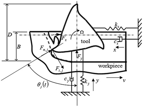
The dynamical model shown in Figure is a two degree of freedom (2DOF) depiction of an end-milling tool that vibrates in the x − y plane (horizontal plane). This is the more relevant model when the tool is compliant in both the feed direction (x direction) and feed normal direction (y direction). The modal parameters and cx are for x-vibration, while
and cy are for y-vibration. The tool is symmetric when the x and y modes of vibration have identical parameters.
Figure 1. Dynamical model of end-milling.
The governing pair of equations of motion becomes(1a)
(1b)
It is seen from Figure that the x and y-components of cutting force on the tool are resolved from the normal and tangential forces
to become
(2a)
(2b)
The non-linear cutting force law for the 2DOF tool becomes(3a)
where and
and
are respective actual feeds in the x and y directions given by
(4a)
(4b)
and w is depth of cut, and
are the tangential and normal cutting coefficients associated with the workpiece material properties and tool shape and Ӽ is the ratio
. Use of non-linear cutting force law for 1DOF modelling of milling process is directly seen in (Insperger, Citation2002; Ozoegwu & Omenyi, Citation2014). The work (Bayly et al., Citation2002) utilized the linear cutting force law with γ = 1 in its 2DOF modelling of milling process. The vibration of the tool has two components, namely the τ-periodic response due to periodic force of tool-workpiece interaction and the regenerative perturbations. The total motions in the x and y directions are respectively, given as sum of feed motions and vibrations thus
(5a)
(5b)
where the notations and
are the respective regenerative perturbations in x and y directions, the notations
and
are the respective τ-periodic responses in x and y directions and vt is the feed motion in x direction. Inserting equations (3, 4 and 5) in Equation (2) gives
where(7)
The term is expanded in linear Taylor series about
to become
(8)
Setting and
to zero in the light of Equation (Equation8
(8) ) causes Equation (1) to become
(9a)
(9b)
where
The periodic forces and
, respectively, drive the two orthogonal τ-periodic tool responses
and
. Putting Equation (9) into (1) and simplifying leads to the coupled 2DOF DDE model for milling process as
(11a)
(11b)
with the specific periodic cutting force variations
Equation (11) put in matrix form reads(13)
where and
(14)
The coupling in the model which stems from the two-dimensional feed of force law is contained in the τ-periodic matrix because of the presence of non-zero off diagonal elements. Making use of state variables
,
,
and
results in the state space form
(15)
where and
(16)
(17)
The natural frequencies and damping ratios of the tool are given in terms of modal parameters and cy, respectively, as
,
,
and
.
It should also be noted that when the feed normal motion of the tool is ignored the terms ,
and
varnish leaving behind
which is now designated with
to give Equation (Equation15
(15) ) for 1DOF system with.
(18)
(19)
and . Only the vibration in the feed direction is considered in 1DOF system. The instantaneous angular position of jth tooth
is given as
(20)
The screen function of the jth tooth is derived in detail in (Ozoegwu, Omenyi, Ofochebe, & Achebe, Citation2013) to be, respectively, given for up-milling and down-milling in terms of and ρ (radial immersion) as
(21)
(22)
It should be noted that linearity of cutting force means that γ = 1 which when substituted in equation (12) gives specific force variations identical with those in (Insperger & Stépán, Citation2004) given directly on the bases of linear force law. The advantage of the form of the presented specific force variations is that non-linear cutting force cases like γ = 0.75 and 0.8 can be investigated straightaway.
3. The generalized p-order least squares modelling of the milling state term
The discrete delay τ is divided into k equal time intervals leading to equation (Equation15(15) ) becoming equation (Equation23
(23) ) in a typical discrete interval
where
,
. The discretization integer k is normally called the approximation parameter in the literature.
(23)
The local delay differential equation (Equation23(23) ) is solved by being integrated between the limits ti and ti+1 to become
(24)
Least squares method is then used to approximate the state term , the delayed state
and the time periodic coefficient
to allow for evaluation of the Duhamel term of equation (Equation24
(24) ). Taking a cue from the generalized least squares method given in (Ozoegwu, Citation2014), it is considered that the state term is approximated as a polynomial
where
is the polynomial of basis vector of p-order and
is the vector of coefficients also of p-order. Since
is known at every discrete time ti as
the p-order least squares approximation of
results from minimizing the error functional
,
as follows;
to give the minimum-error coefficient vector
(25)
The general p-order least squares approximation of then becomes
(26)
What is then required to generate a p-order least squares model of is inserting any chosen value of p in equation (Equation26
(26) ). The summation signs are considered as multiplying each of the elements of the matrix
and vector
. A very important simplification that should be introduced immediately after the formation of the matrix
and vector
is the substitutions si − r = −rΔt,
. This brings to the barest minimum the amount of analysis associated with matrix inversion in equation (Equation26
(26) ). Without these simplifying substitutions introduced at the stage, recommended analytical requirements for handling equation (Equation26
(26) ) could become prohibitive with rise in order of approximation. This recommendation is the gateway to the use of equation (Equation26
(26) ) beyond the second order. It should be noted that if the substitutions were made at this stage in the earlier work (Ozoegwu, Citation2014), second-order least squares modelling of milling state term would have been much shorter.
4. The third-order state term for discrete mapping and stability analysis
The third-order or cubic least squares approximation of the state term is seen from substituting p = 3 in equation (Equation26
(26) ) to be given by
(27a)
(27b)
The simplifying substitutions ti − 2 = −2Δt, ti − 1 = −Δt ti = 0 and ti + 1 = Δt are put in equation (Equation27b(27b) ) with implementation of matrix inversion to give
(27c)
Carrying out the matrix multiplication in equation (Equation27c(27c) ) and re-arranging gives the third-order least squares approximation of the state term
as
(28)
It is seen that the third-order least squares model for follows the simple trend recognized in (Ozoegwu, Citation2014) for the general order least squares approximated state term. The simple trend is taking the value of discrete state that corresponds to the substituted discrete time;
,
,
and
=
. This trend is recommended as a means of ascertaining accuracy of general order least squares approximated state term. The third-order Newton interpolation polynomial used for
in (Quo et al., Citation2012) gives a much more difficult discrete trend;
,
=
,
and
=
.
The least squares approximation of delayed state and periodic matrix
is restricted to first order thus
(29)
(30)
Equations (28, 29 and Equation30(30) ) are inserted in the Duhamel term of equation (24) and solved to give
(31)
where(32a)
(32b)
(32c)
(32d)
(32e)
(32f)
(32g)
(32h)
(32i)
(32j)
(32k)
(33a)
(33b)
(33c)
(33d)
(33e)
(33f)
(33g)
Re-arranged, Equation (31) becomes(34)
where(35)
The discrete map of the system is created from equation (34) to have the monodromy matrix(36)
where(37)
(38a)
(38b)
(38c)
(38d)
(38e)
Since milling discrete map based on state term modelled by third-order interpolation theory exists in the literature (Quo et al., Citation2012) it becomes pertinent at this point to compare its rate of convergence, accuracy and stability results with the third-order least squares approximated discrete map proposed in this section. This is done in the next two subsections of this section after which higher order least squares approximated discrete maps are considered in the subsequent sections.
4.1. Numerical estimate of rate of convergence
The parameters used in all numerical computations in this work which are identical with the experimentally determined parameters of (Bayly et al., Citation2002) are compiled in Table . Table reflects symmetry of the 2DOF tool in which parameters are the same in the feed and feed normal directions. The properties of the laptop computer used for computations are as follows: manufacturer; Hewlett-Packard, Model; Presario CQ61 notebook PC, Rating; 3.9 (Windows Experience Index), Prosessor; AMD Sempron(tm) M120 2.10 GHz, Installed Memory (RAM); 2.00 GB (1.75 GB usable), System type; 64-bit Operating system.
Table 1. Parameters for numerical computations.
The rate of convergence of maps at chosen parameter combinations is estimated here by considering how fast the function converges to zero with rise in k. The function
is the magnitude of the difference of absolute value of the maximum-magnitude characteristic multiplier of the system
and the absolute value of the maximum-magnitude characteristic multiplier of the system at reference approximation parameter kR designated
. The quantity
is considered exact because kR is chosen to be high enough. The map with faster convergence demonstrates
that is closer to zero.
Rate of convergence plots is generated using the presented third-order least squares approximated map (3rd order LSA), second-order least squares approximated map (2nd order LSA) and first-order least squares approximated map (1st order LSA) for fully immersed 1DOF system as shown in Figure . Detailed development of 1st order LSA (the case p = 1 in Equation (26)) and 2nd order LSA (the case p = 2 in Equation (26)) can be seen (Ozoegwu, Citation2014). The cutting process parameters used are presented in the caption of Figure and are identical with those used in (Quo et al., Citation2012) for the purposes of direct comparison. The axes of the plots are also chosen to be of equal extent as those of (Quo et al., Citation2012) for ease of comparison. It is seen that the order of ascending convergence is 1st order LSA, 2nd order LSA and 3rd order LSA. It is instructive to note that rate of convergence of the presented method and that of Quo et al. (Citation2012) is almost identical (only slight differences are seen at low values of k).
Figure 2. Convergence of characteristic multipliers of fully immersed 1DOF system relative to a reference value given in Ding et al. (Citation2010b) at Ω = 5000 and (a)
m (stable operation) with
, (b)
m (unstable operation) with
and (c)
m (unstable operation) with
. It is seen that the 3rd order least squares approximation (3rd order LSA) exhibits the fastest relative convergent followed by 2nd order LSA then the 1st order LSA. It should also be noted that the convergence of the presented 3rd order LSA is very similar with that of Quo et al. (Citation2012).
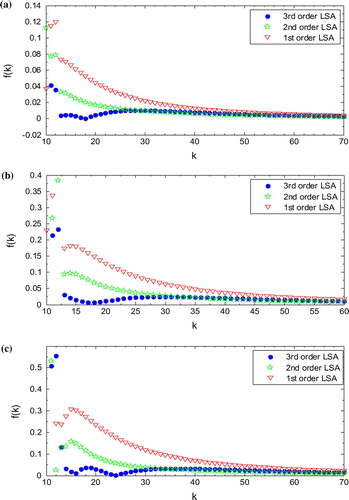
Following similar procedure as in (Insperger, Citation2010), it is demonstrated that the local error of the presented map is this explains its very similar convergence behaviour with that of Quo et al. which is also reported to be of error
.
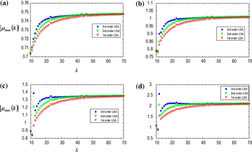
Rate of convergence plot of 2DOF milling system is not seen in the covered literature so it is deemed relevant for presentation in this report. The asymptotic behaviour of with rise in k will be used to investigate the rate of convergence of the two degree of freedom system. A faster map will approach faster an asymptote defined by the exact value of
at infinitely high value of k. The asymptotic numerical rate convergence for the presented 3rd order LSA, 2nd order LSA and 1st LSA order is combined in each component of Figure . The process parameters at which Figure is generated are contained in the caption. It is seen that in accordance with result from error analysis that 3rd order LSA demonstrates the fastest convergence behaviour followed by 2nd order LSA then 1st order LSA. It is clearer from Figure than Figure that 3rd order LSA converges faster than the 2nd order LSA.
Figure 3. The asymptotic rate of convergence of the third order least squares map of fully immersed 2DOF milling process at Ω = 5000 and (a) m (stable operation), (b)
m (unstable operation), (c)
m (unstable operation) and (c)
m (unstable operation). It is seen that 3rd order LSA exhibits the fastest asymptotic behaviour thus the most convergent followed by 2nd order LSA then the 1st order LSA.
4.2. Third-order least squares approximated Stability Lobes
It should be noted that the analytical structure of the presented method liberates 11 matrices (
) to be computed once for all depths of cut of same spindle speed. This means that the
matrices are only computed S times where S is the number of grid points on the spindle speed axis. The calculations that make up for this in the method of (Quo et al., Citation2012) are done at all depths of cut. This means that the make-up calculations are done S × W times where W is the number of grid points on the depth of cut axis. Obviously savings in CT are expected. As noted in (Ozoegwu, Citation2014), the number of
matrices increases from 3 to 2n + 5 when the order of approximation increases from 1 to n. This means that the number of the liberated
matrices is 3, 9 and 11 for 1st order LSA, 2nd order LSA and 3rd order LSA, respectively, suggesting that relative to map of the interpolation theory of same order savings in CT rise with n. This has been shown to be true in (Ozoegwu, Citation2014) where 1st order LSA and 2nd order LSA, respectively, saved 13 and 21% of CT. It will be seen in what follows that the presented 3rd order LSA saves more CT than 2nd order LSA as expected.
The monodromy matrix must have eigenvalues existing on the unit circle centred at the origin of the complex plane for stability. The stability lobes are numerically tracked based on this stability criterion and plotted as critical depth of cut as a function of critical spindle speed. This is done by computing eigenvalues of
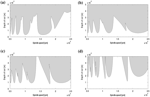
with k = 40 on a 200 by 100 gridded plane of spindle speed and depth of cut. The generated stability diagrams for the down-milling mode (using Equation (22) for screen function) are presented in Figure . Figure should be compared with those in the literature (Ding et al., Citation2010b; Insperger & Stépán, Citation2004) that are generated using identical set of parameters to see the close similarity and thus the applicability of the proposed 3rd order LSA map. The CT for each diagram using the currently proposed 3rd order LSA is contained in the caption. Using the form of milling models presented in this work in the method proposed by Quo et al. (Citation2012), the equivalent stability diagrams are computed and given with CT’s in Figure . The MATLAB programs written for both the presented 3rd order LSA map and the map of (Quo et al., Citation2012) are identical except that the relevant matrices are inserted at appropriate points to avoid bias. It is seen that the two methods produce similar stability boundaries, while 3rd order LSA computes much faster. Relative to the map of (Quo et al., Citation2012), the presented discrete map leads to about 30% gain in CT. It is seen that as expected the presented 3rd order LSA saves more CT than the 2nd order LSA that was seen in (Ozoegwu, Citation2014) to save 21% of CT. It is even more striking to note that against the general notion that an increase in the order of interpolation causes increase in CT (Ding et al., Citation2010b; Quo et al., Citation2012), the proposed 3rd order LSA map is faster than the first-order and second-order interpolation-based maps proposed by Ding et al. (Citation2010a,Citationb), respectively. For example, Figure (a) and (c) took 442 and 413 s, respectively, but the equivalent figures are computed from the method of (Ding et al., Citation2010a) to take 488 and 468 s, respectively, and also computed from the method of (Ding et al., Citation2010b) to take 556 and 531 s, respectively. The presented method further consolidates the earlier notion (Ozoegwu, Citation2014) that least squares modelling of milling state term is powerful for minimizing CT and gets even more powerful in this respect with rise in order of approximation.
Figure 4. Stability lobes of 1DOF down-milling mode of the system from the proposed third order least squares map at (a) radial immersion ρ = 1 with computational time CT = 442 (b) with CT = 460 s (c) ρ = 0.1 with CT = 413 s and (d) ρ = 0.05 with CT = 457 s. It is seen from comparing these CTs with those of Figure 4 that the proposed map is on average about 30% faster than the method of (Quo et al., Citation2012).
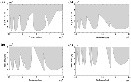
Figure 5. Stability lobes of 1DOF down-milling mode of the system from the method of (Quo et al., Citation2012) at (a) radial immersion ρ = 1 with CT = 636 s (b) with CT = 618 s (c) ρ = 0.1 with CT = 627 s and (d) ρ = 0.05 with CT = 617 s.
The generated stability diagrams for the up-milling mode (using Equation (21) for screen function) are presented in Figure . Application of the presented map to stability analysis of 2DOF down–milling is demonstrated by generating Figure , while application to stability analysis of 2DOF up-milling is demonstrated in Figure .
Figure 6. Stability lobes of 1DOF up-milling mode of the system from the proposed third-order least squares map at (a) radial immersion ρ = 1 with computational time CT = 438 s (b) with CT = 419 s (c) ρ = 0.1 with CT = 455 s and (d) ρ = 0.05 with CT = 415 s.
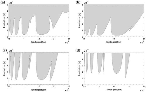
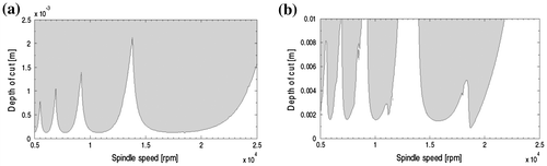
Figure 7. Stability lobes of 2DOF down-milling mode of the system from the proposed third-order least squares map at (a) radial immersion ρ = 1 and (b) ρ = 0.05. These results should be compared with the equivalent stability diagrams in (Quo et al., Citation2012) to see close similarity.
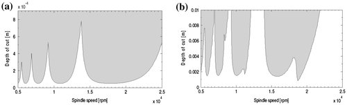
Figure 8. Stability lobes of 2DOF up-milling mode of the system from the proposed third-order least squares map at (a) radial immersion ρ = 0.5 and (b) ρ = 0.05.
Wu, Luo, and Zhang (Citation2013) provided an instructive screening procedure that identifies data points close to the stability limit (the so-called valid region) and used the full-discretization method of Ding et al. (Citation2010a) in computing the monodromy operators at these data points. They reorganized computational itinerary of an existing method by eliminating seemly unnecessary computations with the aim of saving computational time. It is shown in the work of Ozoegwu, (Citation2014) that the least squares approximated full-discretization methods save considerable time relative to the interpolation-based full-discretization methods presented in the works (Ding et al., Citation2010a,Citationb; Insperger, Citation2010; Quo et al., Citation2012) thus anyone implementing the screening procedure of Wu et al. Citation(2016) and uses the least squares approximated full-discretization methods instead of their interpolation-based counterparts in computations within the valid region will much further save computational time and thus further enhance speed of machining parameter selection in the workshop.
5. Conclusion
The general least squares model for milling process state term is presented. This kind of model is used in discrete mapping needed for stability analysis of milling process chatter. The effectiveness and computational time (CT) of the map generated using third-order case of the proposed general state term model are judged against that of Quo et al. (Citation2012) that is based on the third-order interpolation theory. A gain of about 30% in CT is demonstrated by the proposed map. This beneficial result derives from the fact that the presented method results in monodromy matrix that is formed with less number of computations. It should be noted that the first- and second-order least squares approximation theory, respectively, saved 13 and 21% of CT thus the resulting 30% savings from the third-order theory are consistent with the conclusion in (Ozoegwu, Citation2014) that CT savings grow with order of approximation. Numerical rate of convergence analysis (NRCA) of both 1DOF and 2DOF systems is carried out. The NRCA shows that convergence of the 1DOF system using the presented third-order map is very similar with that of the map (Quo et al., Citation2012). The major contribution of this work to the production and manufacturing industry is that a method of milling stability analysis that saves 30% of computational time of the state of art with full retention of accuracy is presented. This will allow faster stability characterization of milling process that will provide the machinist greater freedom in systematic selection of milling process parameters.
Disclosure statement
No potential conflict of interest was reported by the authors.
References
- Altintas, Y. (2001). Analytical prediction of three dimensional chatter stability in milling. JSME International Journal Series C, 44, 717–723.10.1299/jsmec.44.717
- Altintas, Y., & Budak, E. (1995). Analytical prediction of stability lobes in milling. CIRP Annals – Manufacturing Technology, 44, 357–362.
- Bayly, P. V., Halley, J. E., Mann, B. P., & Davies, M. A. (2003). Stability of interrupted cutting by temporal finite element analysis. Journal of Manufacturing Science and Engineering, 125, 220–225.10.1115/1.1556860
- Bayly, P. V., Schmitz, T. L., Stepan, G., Mann, B. P., Peters, D. A., & Insperger T. (2002). Effects of radial immersion and cutting direction on chatter instability in end-milling. Proceedings of IMECE’02 2002 ASME International Mechanical Engineering Conference & Exhibition New Orleans, LA, November 17–22.
- Bobrenkov, O. A., Khasawneh, F. A., Butcher, E. A., & Mann, B. P. (2010). Analysis of milling dynamics for simultaneously engaged cutting teeth. Journal of Sound and Vibration, 329, 585–606.10.1016/j.jsv.2009.09.032
- Ding, Y., Zhu, L. M., Zhang, X. J., & Ding, H. (2010a). A full-discretization method for prediction of milling stability. International Journal of Machine Tools and Manufacture, 50, 502–509.10.1016/j.ijmachtools.2010.01.003
- Ding, Y., Zhu, L., Zhang, X., & Ding, H. (2010b). Second-order full-discretization method for milling stability prediction. International Journal of Machine Tools and Manufacture, 50, 926–932.10.1016/j.ijmachtools.2010.05.005
- Faassen, R. P. H., van de Wouw, N., Oosterling, J. A. J., & Nijmeijer, H. (2003, November). Prediction of regenerative chatter by modelling and analysis of high-speed milling. Internati0onal Journal of Machine Tools and Manufacture, 43, 1437–1446.10.1016/S0890-6955(03)00171-8
- Hanna, N. H., & Tobias, S. A. (1974). Theory of nonlinear regenerative chatter. Journal of Engineering for Industry, 96 Ser B(1), 247–255.10.1115/1.3438305
- Insperger, T. (2002). Stability analysis of periodic delay-differential equations modelling machine tool chatter (PhD dissertation). Budapest University of Technology and Economics.
- Insperger, T. (2010). Full-discretization and semi-discretization for milling stability prediction: Some comments. International Journal of Machine Tools and Manufacture, 50, 658–662.10.1016/j.ijmachtools.2010.03.010
- Insperger, T., & Stépán, G. (2004). Updated semi-discretization method for periodic delay differential with discrete delay. International Journal for Numerical Methods in Engineering, 61, 117–141.10.1002/(ISSN)1097-0207
- Mann, B. P., Bayly, P. V., Davies, M. A., & Halley, J. E. (2004). Limit cycles, bifurcations, and accuracy of the milling process. Journal of Sound and Vibration, 277, 31–48.10.1016/j.jsv.2003.08.040
- Merdol, S. D., & Altintas, Y. (2004). Multi frequency solution of chatter stability for low immersion milling. Journal of Manufacturing Science and Engineering, 126, 459–467.10.1115/1.1765139
- Merrit, H. E. (1965). Theory of self-excited machine-tool chatter. Journal of Engineering for Industry, 87, 447–454.10.1115/1.3670861
- Moon, F. C. (1998). Dynamics and chaos in manufacturing process. New York, NY: Wiley.
- Ozoegwu, C. G. (2011). Chatter of Plastic Milling CNC Machine (Master of Engineering thesis). Nnamdi Azikiwe University Awka.
- Ozoegwu, C. G. (2014). Least squares approximated stability boundaries of milling process. International Journal of Machine Tools and Manufacture, 79, 24–30.10.1016/j.ijmachtools.2014.02.001
- Ozoegwu, C. G., & Omenyi, S. N. (2013, July–August). Wave attenuation effects on the chatter instability of end-milling. Noise Control Engineering Journal, 61, 436–444.10.3397/1/3761038
- Ozoegwu, C. G., & Omenyi, S. (2014). Reducing computational requirement of stability analysis of milling by partial averaging. Manufacturing Review, 1(14), 1–13.
- Ozoegwu, C. G., & Omenyi, S. N. (2016). Curvature effects on circular feed end-milling, part 2: Stability analysis. International Journal of Engineering Systems Modelling and Simulation, 8(1), 20–27. Retrieved from http://www.inderscience.com/info/ingeneral/forthcoming.php?jcode=ijesms
- Ozoegwu, C. G., Omenyi, S., & Ofochebe, S. M. (2013). Time finite element chatter stability characterization of a three tooth plastic end-milling CNC machine. American Journal of Computational and Applied Mathematics, 3(1), 1–7.
- Ozoegwu, C. G., Omenyi, S. N., & Ofochebe, S. M. (2015). Curvature effects on circular feed end-milling, part 1: modelling and simulation. International Journal of Engineering Systems Modelling and Simulation, 7(3), 147–157. Retrieved from http://www.inderscience.com/info/ingeneral/forthcoming.php?jcode=ijesms
- Ozoegwu, C. G., Omenyi, S. N., Ofochebe, S. M., & Achebe, C. H. (2013). Comparing up and down milling modes of end-milling using temporal finite element analysis. Applied Mathematics, 3(1), 1–11.
- Patel, B. R., Mann, B. P., & Young, K. A. (2008). Uncharted islands of chatter instability in milling. International Journal of Machine Tools & Manufacture, 48, 124–134.
- Quo, Q., Sun, Y., & Jiang, Y. (2012). On the accurate calculation of milling stability limits using third-order full-discretization method. International Journal of Machine Tools & Manufacture, 62, 61–66.
- Sellmeier, V., & Denkena, B. (2011). Stable islands in the stability chart of milling processes due to unequal tooth pitch. International Journal of Machine Tools & Manufacture, 51, 152–164.
- Stepan, G. (1989). Retarded dynamical systems. Harlow: Longman.
- Taylor, F. W. (1907). On the art of cutting metals. Transactions of ASME, 28, 31–350.
- Tlusty, J., & Polacek, M. (1963). The stability of machine tools against self-excited vibrations in machining. International research in production engineering, 1(1), 465–474.
- Wiercigroch, M., & Budak, E. (2001). Sources of nonlinearities, chatter generation and suppression in metal cutting. Philosophical Transactions of the Royal Society London, 359, 663–693.10.1098/rsta.2000.0750
- Wiercigroch, M., & Krivtsov, A. M. (2001). Frictional chatter in orthogonal metal cutting. Philosophical Transactions: Mathematical, Physical and Engineering Sciences (Series A), 359, 713–738.10.1098/rsta.2000.0752
- Wu, B., Luo, M., & Zhang, D. (2013). An efficient approach for identifying stable lobes with discretization method. Advances in Mechanical Engineering, 2013, 1–5. doi:10.1155/2013/682684
- Yi, S., Nelson, P. W., & Ulsoy, A. G. (2007). Delay differential equations via the matrix lambert w function and bifurcation analysis: application to machine tool chatter. Mathematical Biosciences and Engineering, 4(2), 355–368.10.3934/mbe