
ABSTRACT
In the context of the Industry 4.0 and of the digital factory, digital twin and virtual reality represent key technologies to design, simulate and optimize cyber-physical production system and interact with it remotely or in a collaborative way. Moreover, these technologies open up new possibilities which can be involved in the co-design and ergonomics studies of workstations, based on Industry 4.0 components like cobots. In order to satisfy these needs and to create dynamic and immersive virtual environment, it is therefore necessary to combine the capacities of the digital twin to perform simulation of the production system with the capacities of the immersive virtual environment in term of interactions. This paper proposes a co-simulation and communication architecture between digital twin and virtual reality software, then it presents a use case on a human-robot collaborative workplace design and assessment.
1. Introduction
The integration of Industry 4.0 components and the development of digital technologies can lead to more efficient and more flexible processes in order to manufacture a variety of high-quality products with a reduction of cost and time, giving a significant competitive advantage (Rüßmann et al., Citation2015). When gathered, flexible manufacturing systems, industrial internet of things, simulation, big data analysis, and cloud manufacturing, lead to a Cyber-Physical Production System (CPPS) (Monostori, Citation2014). Several authors demonstrate the benefits of CPPS deployment within Industry 4.0 thanks to more relevant analysis and management (Colombo, Karnouskos, & Bangemann, Citation2014; Lee, Bagheri, & Kao, Citation2015; Wang, Orban, Cunningham, & Lang, Citation2004). In order to make optimal decisions, a CPPS needs to include a digital representation of the real system.
1.1. Digital twin
One of the most prevalent technologies is the digital twin (Uhlemann, Lehmann, & Steinhilper, Citation2017), since it can be used to simulate the components involved in the system. They indicate that the digital twin could share data (either real-time data or offline data) with the production system. For Boschert and Rosen (Citation2016), the digital twin is the linked collection of the digital artefacts of component and system, and the digital twin evolves with the real system. Boschert and Rosen (Citation2016) indicate that the digital twin is also connected to existing IT-systems to use the available digital information. Digital twin is used to run simulations and acts as a process-monitoring tool to search for potential incidents, retrieve performance metrics, prevent failure, and then optimize the real system (Ojstersek & Buchmeister, Citation2017). Those approaches, which combine the real system behaviour with its virtual representation, allows dealing with many optimization problems, such as the deficiency and the lack of control over the data, fragmented between different parts of the system while getting a realistic representation of the system. In that sense, digital twin is an evolution of monitoring, diagnostics, and optimization tools, based on a web-based approach, developed before the introduction of the Industry 4.0 (Moore et al., Citation2008; Wang et al., Citation2004). In (Moore et al., Citation2008), a 3D virtual engineering approach (VIR-ENG) is proposed to access data, through a web service or a socket connection, in order to perform Internet-based monitoring integrated into virtual engineering tools.
Digital twin is also usable for design. Tao et al. (Citation2018) propose a new method for product design, product manufacturing, and product service driven by the digital twin to conserve unicity and centralization of data. Nowadays, in addition to the control of information, digital systems tend to be more and more autonomous and become a relevant decision-maker, able to assist humans in real-time in the most efficient way. Rosen, von Wichert, Lo, and Bettenhausen (Citation2015) deal with the challenges of smart industry by focusing on digital twin to ensure modularity, connectivity, and autonomy of industrial systems.
CPPS including a digital twin is a very powerful tool to aim for the best possible performance of a production system but it can hardly be fully autonomous. Human interventions are frequently needed to control and run the production system and also to design or re-design the process. For that reason, there is a strong need of human to CPPS interfaces.
1.2. Virtual reality
Virtual reality (VR), thanks to its natural acting capabilities, is a well-adapted mean to help a human interact with a CPPS. Indeed, virtual reality offers immersive 3D scale-one visualization, realistic rendering, natural gesture interactions, collaboration functionalities, and a quick navigation tools in wide area. Therefore, it allows users to easily focus on every component of the system, from the smallest one to the whole factory. It is moreover increasingly easier to implement and use thanks to unceasing progress in dedicated hardware and software. Virtual reality is used in several activities in industry: product or process design (Berg & Vance, Citation2017; Smparounis et al., Citation2009), facility layout (Menck et al., Citation2012), training (Marzano, Friel, Erkoyuncu, & Court, Citation2015), or remote collaboration (Galambos et al., Citation2015). Virtual reality helps to do right first time and involves stakeholders in the decision process (Gong, Berglund, Saluäär, & Johansson, Citation2017). For example, Abidi, Lyonnet, Chevaillier, and Toscano (Citation2016) show the positive contribution that virtual reality can have on a lean production system to minimize production times and eliminating waste of time.
Moreover, Bougaa, Bornhofen, Kadima, and Rivière (Citation2015) show that virtual reality allows involving and engaging all stakeholders in the decision process. As instance, operators’ ergonomics can be assessed thanks to virtual environment in order to increase the comfort at work (Bäckstrand, Hogberg, De Vin, Case, & Piamonte, Citation2007; Högberg et al., Citation2007). Recent works deal with assessing ergonomics in a real situation thanks to motion capture (Bortolini, Faccio, Gamberi, & Pilati, Citation2018) or within simulated situation in virtual reality (Rizzuto, Sonne, Vignais, & Keir, Citation2019).
Virtual reality is also used for training as explained in (Berg & Vance, Citation2017) and is an efficient and safe tool. As an example, Sousa, Ribeiro Filho, Nunes, and Da Costa Lopes (Citation2010) present a virtual reality environment for Hydroelectric Power Unit (HPU) servicing and maintenance. Each module contains three levels of difficulty (watch only, guided, autonomous) to progressively learn. In same way Saunier, Barange, Blandin, and Querrec (Citation2016) propose two training virtual reality environments about wind turbine. One to learn the principle and components of energy conversion and another one dedicated to the learning of safety procedures by maintenance operators for interventions in wind turbines. Another use of virtual reality is assembly training. Marzano et al. (Citation2015) use his VR_MATE framework to produce a virtual reality environment for assessing and training operators to assemble a locomotive or to disassemble a plane. These scenarios allow assessing the feasibility and evaluating the operator’s body posture during the scenario. The interesting point that Ganier, Hoareau, and Tisseau (Citation2014) show is that virtual reality training on a maintenance procedure is transferred as well as a training on the real object. Ordaz, Romero, Gorecky, and Siller (Citation2015) also show that gaming experience has no impact on the learning transfer. As a last example, Matsas and Vosniakos (Citation2017) present a virtual reality tool where a human and a robotic arm collaborate. Whereas the robotic arm does not fully behave as in reality, the virtual reality training allows the operator to understand how to safely behave during the collaboration.
1.3. Digital twin and virtual reality
In order to train people in virtual reality with systems that realistically behave, there is an interesting potential in combining virtual reality and digital twin technologies. Turner, Hutabarat, Oyekan, and Tiwari (Citation2016) namely demonstrate the benefits provided by this association by reviewing different case studies where discrete event simulation is combined with virtual reality. For now, simulation software usually shows a lack of virtual reality functionalities. Digital factory CAD tools like (Dassault Systems, Citation2018) introduced recently some virtual reality visualization capabilities but with restricted interactions and collaboration features. That is why it would be interesting and wise to develop the connectivity between simulation and virtual reality software to take advantage of their strength and to avoid redundant development between applications. The possibility of co-simulation through real-time data exchange between those two types of software could allow training or designing session in dynamic virtual environments.
Functional Mock-up Interface (FMI) is a software independent standard to support both model exchange and co-simulation of dynamic models using a combination of xml-files and compiled C-code (FMI, Citation2018). It is a particularly appropriate standard to develop CPPS and data exchange between simulation and virtual reality applications. For example, Waurich and Weber (Citation2017) propose a Functional Mock-Up Unit (FMU) developed in C++ that allows the visualisation in virtual reality software (Unity) of an excavator model driven by simulation software (OpenModelica). Unity is used to provide a graphically satisfying view of the model within a realistic environment while the use of OpenModelica ensures a relevant behaviour of the system model. This combination is developed to compensate the lack of contextualisation and visualization possibilities of simulation software, thus giving better understanding and analysis on the system.
Finally, we can see that several tools are involved for developing the digital twin. Each has advantages and drawbacks and do not have the same features. As a result, this article, which is an extended version of our work presented in (Lacomblez, Jeanne, Havard, & Baudry, Citation2018), aims to propose a generic and reusable architecture of co-simulation application between a digital twin and a virtual reality environment in the context of industry 4.0, based on ZMQ socket machine-to-machine communication (Meng, Wu, Muvianto, & Gray, Citation2017).
The rest of the paper is organized like this. First, we will position the digital twin associated with the virtual reality tool in the process of designing or redesigning an element of a production system. Then, the proposed technical architecture allowing co-simulation between the digital twin and the virtual reality environment is presented. This architecture is illustrated by the co-simulation of an UR10 6-DOF cobotic arm where simulations of motion are performed within a digital factory suite (Dassault Systems, Citation2018) and virtual reality interactions and simulations within a dedicated software based on Unity. Then, the proposed co-simulation architecture and tools are studied as an assessment tool for the operator’s safety and ergonomics during the design of industrial workstations. Perspectives to exploit this co-simulation environment for virtual reality operator training are also discussed.
2. Using digital twin associated to virtual reality as an engaging decision tool
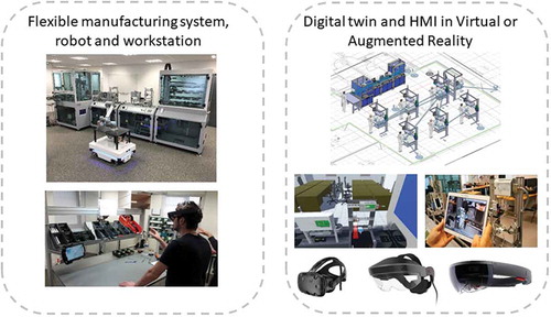
The proposed usage is illustrated on the LINEACT CESI CPPS, a flexible manufacturing system (FMS) involving several robots with different capabilities in a shop floor layout context. This use case is composed of an automatic production system and a set of manual workstations where the operator can be assisted by cobotic arms for assembly tasks. Mobile robots with different capacities and capabilities ensure transportation tasks. Pick and place operation can be ensured by human operator or robotic arms. Several types of product can be manufactured and augmented reality devices can be used to help the operator in production or maintenance tasks. A digital twin associated to Human-machine interface (HMI) based on virtual or augmented reality is also present (see ). In the next sections, the benefits of coupling digital twin and virtual reality in that CPPS are discussed.
Figure 1. Flexible manufacturing system and its digital twin.
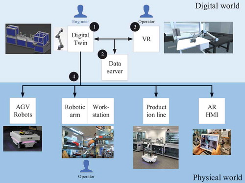
As presented in the introduction, digital twin is a relevant tool for validating a new factory configuration either in a global point of view by flow simulations or for a specific element by defining a new design. However, digital twin lacks realism for human-centred design of manufacturing process and workstation. In that sense, virtual reality is a key tool as it can represent the system at scale one and allow instinctive interactions. As an example, if a new configuration is needed, engineers of the production methods department can design it with the digital twin (indicated with (1) in ). When it is done, the digital twin is used to simulate the new configuration. Then simulated data are shared in real-time with virtual reality through the data server (see (2) in ). Thanks to that approach, end-user operators, getting a realistic behaviour of the factory, can interact with it and finally give their feedbacks about that configuration (see (3) in ). As any requested change is only made in the digital world the cost is much lower than a change on the physical system. Lastly, once the new configuration is validated, the new parameters and software programs can be deployed to the physical system thanks to the digital twin. The human-centred tool, such as augmented reality is also updated with the new configuration to support maintenance operations (see (4) in ). In order to show the feasibility of this approach, the next section will describe a more particular case involving a robotic arm and using specific digital twin, data server and virtual reality environment.
Figure 2. Digital twin and virtual reality environment.
3. Co-simulation workflow and architecture between digital twin and a virtual reality environment
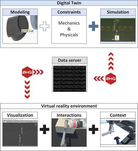
This section describes the proposed architecture and workflow allowing the execution of a co-simulation between the mains tools (see ). To illustrate the co-simulation architecture, we have applied this architecture to a digital twin representation of a UR10 robotic arm. This workflow is composed of a digital factory suite (Dassault Systems, Citation2018) including CAD (Computer-Aided Design), CAM (Computer-Aided Manufacturing) and simulation tool. It allows the conception and simulation of the manufacturing system and components during design or redesign stage (see Digital twin in ). On the other hand, a visualization and interaction tool in virtual reality, based on the 3D engine Unity is proposed. Virtual reality and IT engineers are developing the 3D engine functionalities such as interactions with objects, movement in virtual environment, and integration of the environment (see Virtual reality environment in ). In order not to again develop the system behaviour in virtual reality environment, it is worth using the simulation data provided from the digital twin and used them inside the virtual reality tool. This allows a realistic behaviour of the system inside virtual environment. Conversely, it is worth using virtual reality features (real scale visualization, interactions) and to take them into account inside the simulation. In order to make both tools able to communicate, a data server is needed for exchanging real-time data (see Data server in ). The next section is going to detail how each component of the architecture is exchanging data.
Figure 3. Co-simulation workflow between the digital twin and the virtual reality environment.
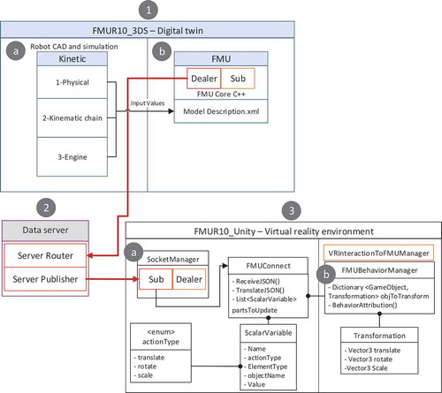
The proposed architecture is divided into three distinct blocks but a continuous communication is kept between them (see ). It is managing real-time data exchange between the digital twin and the virtual reality environment, through a client-server pattern.
Figure 4. Technical architecture to exchange data between the digital twin and the virtual reality environment.
3.1. Digital twin
As presented in the introduction, a digital factory suite (Dassault Systems, Citation2018) is used for the digital twin and more particularly two modules: Catia – functional and logical design and Modelica, to model the system and the associated constraints (indicated with (1.a) in ). The logical model of the robotic arm is constituted by: the physical constraints which represent the gravity and mass of each part of the system (see (1.a) Physical in ), the kinematic chain constraints which represent connection between each part and the parameters associated (friction, limits), and the engine constraints which represent the engine force and torques applied (see (1.a) Kinematic chain in ). Once those parameters are set, the digital twin version of the system is behaving in a realistic way.
From that point, it is necessary to send data about the simulation to the virtual reality environment. As presented in introduction, a co-simulation architecture based on Functional Mock-up Interface is retained and a FMU is developed (see (1.b) in ). It is composed of three major components:
a ModelDescription.xml file, which defines input/output data managed by the FMU. Each of those can transmit the state, in real-time, of a component of the system and are included within a < scalarVariables> tag in the xml file. The naming convention is {Name of the part}_{type of action}_{element concerned} (example: Axis1_rotate_x);
a ModelDescription.xslt file, which automatically parses the ModelDescription.xml file to transform it in a C++ header file (modelDescription.h). C++ variables can thus be used in the FMU Core C++ program;
a FMU Core C++, a binary file which is a compiled plugin (see (1.b) in ). This particular program is developed to transmit all the scalar variables, generated by the simulation done in the digital twin, to the data server, through a socket.
Once compiled, the FMU becomes a new component, in the Modelica software, usable by any person used to work with it. As a result, FMU makes it possible to transmit the logic behaviour of a system to another tool in real-time. In the FMU UR10 presented in this paper, the position and rotation of each part of the robot arm are sent in JSON format to the data server. The next section is describing this mechanism.
3.2. Data server: coordinator of the data transmission
The role of the data server is to deal with the data in order to transmit it to the right virtual reality environment in real time. The data server act as a coordinator and the digital twin and the virtual reality environment represent the clients. In order to manage several clients simulating different part or behaviours of the systems, SimulationID is used. Hence, only clients using the same SimulationID will share their data.
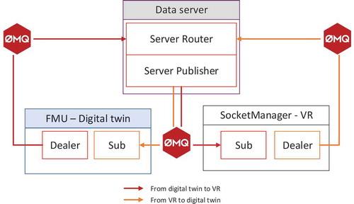
To communicate in real time, the socket technology is chosen. As each digital twin is using different languages, we have chosen the ZeroMQ framework since it has been developed to connect any code to any code. Moreover, Client-Server communication with ZMQ is done asynchronously, that is, processing will not be blocked while another operation is in progress. Thus, it ensures multiple connections by many clients. ZMQ also offers a set of intuitive communication design patterns to suit many requests. In this architecture, the dealer, router, and the publisher subscriber patterns have been used (Hintjens, Citation2013). The dealer, available in the FMU for the digital twin and in the SocketManager in the virtual reality environment, sends data to the router in the data server (see ). Then, the data server sends them through the publisher pattern. Lastly, information is dispatched to all the clients that have subscribed to it. As a result, the digital twin can send data to the virtual reality environment and conversely.
Figure 5. ZMQ subscriber dealer design pattern.
3.3. Virtual reality environment: a visualization and interaction tool in VR for the digital twin
Virtual reality environment is developed in Unity, a powerful C# 3D rendering engine that is used as a visualization and interaction tool. For that, it receives data, thanks to the subscriber pattern. The data received are the scalar variables representing the pose of each part of the robot arm generated by the digital twin. Thanks to the naming convention defined in the digital twin section, InterpretorManager class manages the identification of the part to update, the axis of the part to update and the value to apply on it. On each message received, a list of ScalarVariable, called partsToUpdate, is filled in the FMUConnect class (see (3a) in ). Then the FMUBehaviorManager converts the partsToUpdate list (see (3b) in ) into a Unity object objToTransform. This dictionary is filled with the game object to update and the transformation to apply on it (see (3b) in ). Thus, the application browses the objToTransform Dictionary and apply it. The virtual reality environment will finally display the system arm simulated through the digital twin.
4. Design of workstation involving human and robotic arm collaboration case study
4.1. Case study and design steps workflow
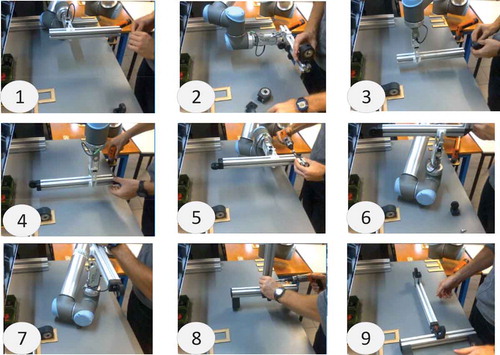
The case study is based on the presented CPPS and particularly focusing on the manual workstation where an operator is working in collaboration with a robotic arm (UR10) to assemble a subassembly of a children’s bike (see ). The assembly process at this workstation consists of 28 operations divided into seven assembly instruction sheets. The human-robot interaction of this hybrid cell is classified into the shared workspace and task category (Tsarouchi, Matthaiakis, Makris, & Chryssolouris, Citation2017). The robotic arm will pick up and present the element being assembled in different orientations and positions in order to help the operator during the assembly steps (see positions (1) to (8) in ). The final subassembly is presented on . Moreover, for ergonomic purposes, the position of the element being assembled and carried by the robotic arm should change according to the operator’s size.
Figure 6. Workstation with cobotic arm.
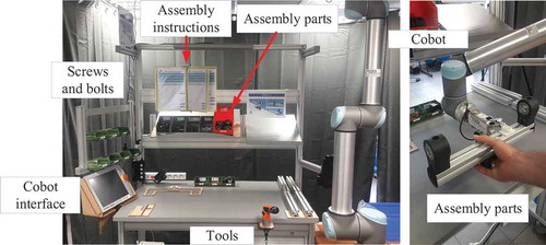
Figure 7. Collaborative assembly with the robotic arm.
presents the proposed workflow that leads to the manual workstation with robotic arm design or redesign. The first steps are to create an initial design of the workstation, to select and program the robotic arm, and to create the assembly instructions. As the end of the design step, a digital prototype is available in the digital twin. In the second step, ergonomics, safety, and robot behaviour assessments are realized on this digital prototype in the virtual reality environment. Several loops between the design and prototype stages could be done. The next section will focus on the digital prototype assessment in virtual reality.
Figure 8. Design process involving digital twin and virtual reality environment.
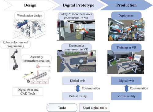
Once all stakeholders validate the design, the workstation is implemented in production and the co-simulation environment is used to train operators in virtual reality. As cobotic represents a new way of collaboration between human and machine, stakeholders need to train themselves to understand how they should behave. By using the ontological model presented in previous research work (Havard, Jeanne, Savatier, & Baudry, Citation2017), the assembly instructions can be converted to create a complete virtual reality training system (see Training in VR in ). This assembly scenario available in virtual reality is also used during the digital prototype step by the operators for assessment of the configuration, safety, and ergonomics of the workstation (see Digital prototype step in ).
4.2. Digital prototype assessment in virtual reality
4.2.1. Safety & robot behaviour assessments in VR
Digital Twin can simulate the robotic arm behaviour. Engineers can program and set different positions the robot must take at each operation step. In this case study, nine positions of the robotic arm must be defined. The design of kinematics to reach these different positions are done through the robot simulation module of the digital twin. Then through the co-simulation framework, the digital twin provides the robotic arm movement to the virtual reality environment. As a result, the robotic arm realistically behaves and the engineers who conceive the program can check the robot behaviour in virtual reality. Moreover, the tuning of the robotic arm can be done without using the real equipment and thus it avoids interrupting a current production process.
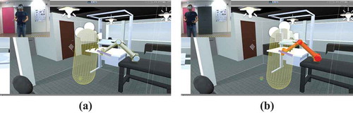
Virtual reality allows also validating the robotic arm behaviour with a real operator involved in the scene. As human and robot shared tasks and workspace, it is mandatory to safely test and check that the robotic arm will not collide with any part of the workstation or hurt the operator (see ). What is fundamentally different between virtual reality and simulation through digital twin is that, in virtual reality, the operators are real persons acting and taking risks, as they would do on the real workstation. As an example in , the same operator has performed several times the same assembly task inside the virtual reality environment. With the habits, the operator has approached the robotic arm and it has collided with him. When a collision occurs, the virtual reality engine detects it and can report it, by putting the robotic arm in red (see (b) in ). In such a case, the configuration of the manual station or the program of the robotic arm must be reconsidered.
Figure 9. Safety checking in virtual reality thanks to the collision detection.
4.2.2. Ergonomics assessment in VR
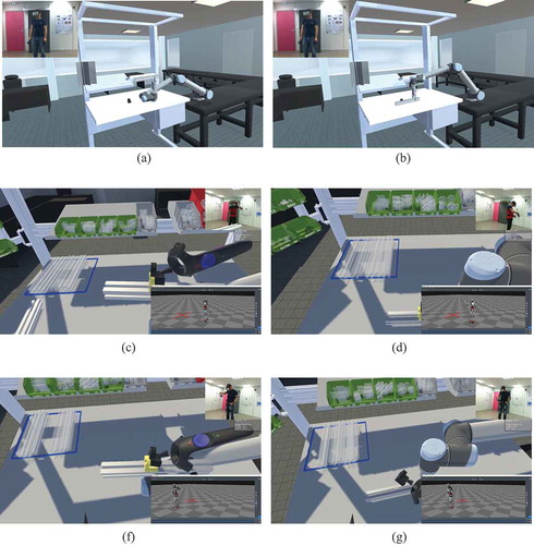
As virtual reality engages operator into the process, configuration and ergonomics assessments of the workstation can be addressed during the process. It has been conducted into the virtual reality environment presented on . This co-simulation environment reduces the delay and costs as modification of the design in the digital twin are tested on the digital prototype and not a physical one. On the basis of this co-simulation architecture and the available digital porotype in virtual reality, we studied the possibility of carrying out ergonomics studies according to the operator’s characteristics. As instance, the operator’s comfort and ergonomics can be taken into account. To illustrate the study, we select, for example, an assembly step where the robot position can be set to two different positions: a high and a low one (see (a) and (b) in ). In order to choose the best robot position according to the operator, we choose to make a tall and a small operator perform the operation in VR to evaluate the both robot configurations. Operator is first equipped with a suit to get position of his skeleton in real time; in this case study, we have used a Perception Neuron Pro one. Thanks to the sensor suit, while the operation is carried out, the RULA score is computed at 120 Hz (McAtamney & Corlett, Citation1993). The proposed approach is relevant for three factors. On one hand, computing the RULA score during the whole operation is relevant because we can assess that the entire operation step is ergonomically acceptable, contrary to current industrial approach which bases the analysis only on a few key steps of the procedure. On the other hand, using virtual reality for assessing the workstation allows testing several configurations without keeping busy a real workstation. Finally, a virtual design assessment allows ‘doing well at first time’ and reducing the cost of a redesign in case of any ergonomics misconception. An example of the setup proposed is shown in (c) (d) in , for the small operator, and (e) (f), for the tall operator. In this setup, each operator is performing the first operation step, which needs to assemble four parts and last around 1 min.
Figure 10. Ergonomics assessment in virtual reality environment thanks to the skeleton data. (a) Robotic arm high position; (b) Robotic arm low position; (c) Small operator working with high position; (d) Small operator working with low position; (f) Tall operator working with high position; (g) Tall operator working with low position.
The RULA score computed during the virtual reality session is shown in and . In these figures, the time is normalized from the start and the end of the assembly operation to compare both virtual simulation with the same duration scale. In order to find the best robot position according to the operator’s characteristics, a Wilcoxon test is performed between high and low position for each one. For the tall operator, the results show that there is a significant difference between the high position and the low position (W = 2492267, p-value = 1.963e-10). Therefore, it is ergonomically better, for the tall operator, to use the high position of the robot.
Figure 11. RULA score computed during the VR assembly operation for a tall operator, with robot in high position (in blue) and low position (in orange).
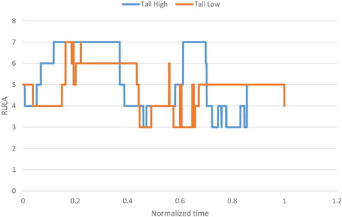
Figure 12. RULA score computed during the VR assembly operation for a small operator, with robot in high position (in blue) and low position (in orange).
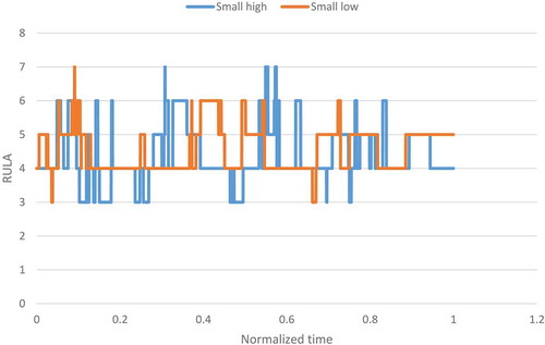
As far as the small operator is concerned, the Wilcoxon test also shows that there is a significant difference between the high position and the low position (W = 8458029, p-value < 2.2e-16). Therefore, it is also ergonomically better, for the small operator, to use the high position of the robot.
This study shows that a virtual reality session allows evaluating the ergonomics of manual workstations assisted by a cobot during an operation step. As a result, it is possible to choose one of the robot position configuration. At first thought, we could expect that the small operator would get a better ergonomics score with the low configuration of the robot. However, the results obtained from the method proposed show the contrary.
Nevertheless, there remain limitations of the virtual reality usage. For instance, operators do not grab parts in exactly the same way in the physical world with their hands as in the virtual reality environment with the controller. However, the operator performs each operation twice, once with the high position of the robot and once with the low position. Thus, any bias due to the part handling discrepancy is limited, making the method suitable as a comparative method.
5. Conclusion and future work
In this article, a real-time co-simulation architecture between a digital twin and a virtual reality environment has been proposed. This real-time co-simulation ensures both a realistic behaviour of the actual system thanks to the simulation provided by the digital twin and a natural interaction interface with its 3D representation thanks to the virtual reality. The proposed solution is composed of a client-server architecture and the real-time machine-to-machine communication uses ZMQ socket to exchange data.
Then, this architecture has been employed on a concrete use case focusing on a manual station where a cobotic arm UR10 is added to help operator in his assembly task. The co-simulation allows getting a realistic behaviour of the robotic arm, and the association with the virtual reality allows: digital prototyping, operator’s safety assessment, and studying the layout and ergonomics of the workstation. The proposed workflow allows an intermediate level of simulation involving human in the digital prototype step compared to virtual ergonomics solution based on digital human model or simulation realized on the physical system.
This architecture and communication method has been validated with the UR10 co-simulation. Thanks to the use of standard tools and scalable architecture, our future research works will be, first, to co-simulate more than one system at the same time and secondly, to be able to use heterogeneous simulation tools, such as Gazebo to simulate mobile robot, and gather their results inside the same virtual reality environment.
Other research perspectives focus on the evaluation of this co-simulation architecture in the context of a dynamic and collaborative (multi-operators) virtual reality training environment.
Acknowledgments
This part of the work is done within the framework of the project XTERM, financed by the FEDER and the Normandy region.
Disclosure statement
No potential conflict of interest was reported by the authors.
Related Research Data
References
- Abidi, M.-A., Lyonnet, B., Chevaillier, P., & Toscano, R. (2016). Contribution of virtual reality for lines production’s simulation in a lean manufacturing environment. International Journal of Computer Theory and Engineering, 8, 182.
- Bäckstrand, G., Hogberg, D., De Vin, L. J., Case, K., & Piamonte, P. (2007). Ergonomics analysis in a virtual environment.
- Berg, L. P., & Vance, J. M. (2017). Industry use of virtual reality in product design and manufacturing: A survey. Virtual Reality, 21, 1–17.
- Bortolini, M., Faccio, M., Gamberi, M., & Pilati, F. (2018). Motion Analysis System (MAS) for production and ergonomics assessment in the manufacturing processes. Computers & Industrial Engineering (p. 105485).
- Boschert, S., & Rosen, R. (2016). Digital twin—the simulation aspect. In P. Hehenberger and D. Bradley. (Eds.) Mechatronic futures: Challenges and Solutions for Mechatronic Systems and their Designers (pp. 59–74). Cham: Springer.
- Bougaa, M., Bornhofen, S., Kadima, H., & Rivière, A. (2015). Virtual reality for manufacturing engineering in the factories of the future. Applied Mechanics and Materials, 789, 1275–1282.
- Colombo, A. W., Karnouskos, S., & Bangemann, T. (2014). Towards the next generation of industrial cyber-physical systems. In Colombo A. et al. (Eds.) Industrial cloud-based cyber-physical systems: The IMC-AESOP Approach (pp. 1–22). Cham: Springer.
- Dassault Systems. (2018). DELMIA. Récupéré sur https://www.3ds.com/fr/produits-et-services/delmia/
- FMI. (2018, April 23). The FMI standard webpage. Récupéré sur www.fmi-standard.org
- Galambos, P., Csapó, Á., Zentay, P., Fülöp, I. M., Haidegger, T., Baranyi, P., & Rudas, I. J. (2015). Design, programming and orchestration of heterogeneous manufacturing systems through VR-powered remote collaboration. Robotics and Computer-Integrated Manufacturing, 33 68–77.
- Ganier, F., Hoareau, C., & Tisseau, J. (2014). Evaluation of procedural learning transfer from a virtual environment to a real situation: A case study on tank maintenance training. Ergonomics, 57, 828–843.
- Gong, L., Berglund, J., Saluäär, D., & Johansson, B. (2017). A novel VR tool for collaborative planning of manufacturing process change using point cloud data. Procedia CIRP, 63, 336–341.
- Havard, V., Jeanne, B., Savatier, X., & Baudry, D. (2017, April 5). Inoovas - industrial ontology for operation in virtual and augmented scene: The architecture. International Conference on Control Decision and Information Technology, Barcelona, Spain.
- Hintjens, P. (2013). ZeroMQ: Messaging for many applications. “ O’Reilly Media, Inc.”.
- Högberg, D., Bäckstrand, G., Lämkull, D., De Vin, L. J., Case, K., Örtengren, R., … Berlin, C. (2007). Towards dynamic ergonomics analysis of work sequences in virtual environments. 17th International Conf. on Flexible Automation and Intelligent Manufacturing (2007 FAIM) (pp. 581–588). Philadelphia, USA.
- Lacomblez, M., Jeanne, B., Havard, V., & Baudry, D. (2018, September 11–13). Co-simulation architecture between a digital twin and a virtual reality environment in an industrial context. Advances in Manufacturing Technology XXXII: Proceedings of the 16th International Conference on Manufacturing Research, incorporating the 33rd National Conference on Manufacturing Research (Vol. 8, p. 429). Sweden: University of Skövde.
- Lee, J., Bagheri, B., & Kao, H.-A. (2015). A cyber-physical systems architecture for industry 4.0-based manufacturing systems. Manufacturing Letters, 3, 18–23.
- Marzano, A., Friel, I., Erkoyuncu, J. A., & Court, S. (2015). Design of a virtual reality framework for maintainability and assemblability test of complex systems. Procedia CIRP, 37, 242–247.
- Matsas, E., & Vosniakos, G.-C. (2017). Design of a virtual reality training system for human–robot collaboration in manufacturing tasks. International Journal on Interactive Design and Manufacturing (ijidem), 11, 139–153.
- McAtamney, L., & Corlett, E. N. (1993). RULA: A survey method for the investigation of work-related upper limb disorders. Applied Ergonomics, 24, 91–99.
- Menck, N., Yang, X., Weidig, C., Winkes, P., Lauer, C., Hagen, H., … Aurich, J. C. (2012). Collaborative factory planning in virtual reality. Procedia CIRP, 3, 317–322.
- Meng, Z., Wu, Z., Muvianto, C., & Gray, J. (2017). A data-oriented M2M messaging mechanism for industrial IoT applications. IEEE Internet of Things Journal, 4, 236–246.
- Monostori, L. (2014). Cyber-physical production systems: Roots, expectations and R&D challenges. Procedia Cirp, 17, 9–13.
- Moore, P. R., Ng, A. H., Yeo, S. H., Sundberg, M., Wong, C. B., & De Vin, L. J. (2008). Advanced machine service support using Internet-enabled three-dimensional-based virtual engineering. International Journal of Production Research, 46, 4215–4235.
- Ojstersek, R., & Buchmeister, B. (2017). Use of simulation software environments for the purpose of production optimization. Annals of DAAAM\& Proceedings, 28.
- Ordaz, N., Romero, D., Gorecky, D., & Siller, H. R. (2015). Serious games and virtual simulator for automotive manufacturing education & training. Procedia Computer Science, 75, 267–274.
- Rizzuto, M. A., Sonne, M. W., Vignais, N., & Keir, P. J. (2019). Evaluation of a virtual reality head mounted display as a tool for posture assessment in digital human modelling software. Applied Ergonomics, 79, 1–8.
- Rosen, R., von Wichert, G., Lo, G., & Bettenhausen, K. D. (2015). About the importance of autonomy and digital twins for the future of manufacturing. IFAC-PapersOnLine, 48, 567–572.
- Rüßmann, M., Lorenz, M., Gerbert, P., Waldner, M., Justus, J., Engel, P., & Harnisch, M. (2015). Industry 4.0: The future of productivity and growth in manufacturing industries. Boston Consulting Group, 9, 54–89
- Saunier, J., Barange, M., Blandin, B., & Querrec, R. (2016). A methodology for the design of pedagogically adaptable learning environments. International Journal of Virtual Reality, 16(1) 15–21.
- Smparounis, K., Alexopoulos, K., Xanthakis, V., Pappas, M., Mavrikios, D., & Chryssolouris, G. (2009, June). A web-based platform for collaborative product design and evaluation. 2009 IEEE International Technology Management Conference (ICE) (pp. 1–9). Leiden, Netherlands. doi:10.1109/ITMC.2009.7461378
- Sousa, D. A., Ribeiro Filho, M., Nunes, M. V., & Da Costa Lopes, A. (2010). Maintenance and operation of a hydroelectric unit of energy in a power system using virtual reality. International Journal of Electrical Power\& Energy Systems, 32, 599–606.
- Tao, F., Cheng, J., Qi, Q., Zhang, M., Zhang, H., & Sui, F. (2018). Digital twin-driven product design, manufacturing and service with big data. The International Journal of Advanced Manufacturing Technology, 94, 3563–3576.
- Tsarouchi, P., Matthaiakis, A.-S., Makris, S., & Chryssolouris, G. (2017). On a human-robot collaboration in an assembly cell. International Journal of Computer Integrated Manufacturing, 30, 580–589.
- Turner, C. J., Hutabarat, W., Oyekan, J., & Tiwari, A. (2016). Discrete event simulation and virtual reality use in industry: New opportunities and future trends. IEEE Transactions on Human-Machine Systems, 46, 882–894.
- Uhlemann, T. H.-J., Lehmann, C., & Steinhilper, R. (2017). The digital twin: Realizing the cyber-physical production system for industry 4.0. Procedia Cirp, 61, 335–340.
- Wang, L., Orban, P., Cunningham, A., & Lang, S. (2004). Remote real-time CNC machining for web-based manufacturing. Robotics and Computer-integrated Manufacturing, 20, 563–571.
- Waurich, V., & Weber, J. (2017, May 15-17). Interactive FMU-based visualization for an early design experience. Proceedings of the 12th International Modelica Conference (pp. 879–885). Prague, Czech Republic.