
 ?Mathematical formulae have been encoded as MathML and are displayed in this HTML version using MathJax in order to improve their display. Uncheck the box to turn MathJax off. This feature requires Javascript. Click on a formula to zoom.
ABSTRACT
Using Servo Testing Machine and Split Hopkinson Pressure Bar measurement device, an experimental study on the electro-mechanical characteristics of PZT5H piezoelectric ceramics under quasi-static and impact loading are carried out. The electromechanical response characteristics of PZT5H under impact load is analyzed emphatically. Results showed that under the condition of static compression and the same maximum loading stress, PZT5H piezoelectric ceramics in the same strain and displacement, the stress value increases with the increase of loading stress rate. Under impact load and the same load, the electric displacement of PZT5H piezoelectric ceramics increases with the increase of strain rate, and the corresponding stress value of the same strain increases with the increase of strain rate. When the strain rate is less than 208/s, the response time of PZT5H piezoelectric ceramics decreases with the increase of strain rate, the failure of electric displacement increases with the increase of strain rate under impact loading.
1. Introduction
Piezoelectric ceramics is a kind of special ceramic material which can convert electrical energy and mechanical energy. It has the advantages of high energy density, high reliability, and high electromechanical coupling coefficient. Piezoelectric ceramics are widely used in automotive sensing (detonation sensor, ultrasonic sensor, acceleration sensor), driving (electric doors and windows, electric rearview mirror, electric seat), vibration isolation, noise reduction, safety monitoring and alarm (airbag, tire pressure monitoring system), and other fields [Citation1–7]. Among them, PZT piezoelectric ceramics are widely used in the automotive field because of their excellent piezoelectric effect and high Curie temperature [Citation8,Citation9]. When a smart material loses the specific function it was intended to achieve, it is called failure. Intelligent sensors embedded in the structure will also be subjected to static or dynamic loads along with the structure. It could cause the sensors to be abnormal or even failure.
In view of the fact that most piezoelectric ceramic components used in the automotive fieldwork under dynamic loads. For example, frequent traffic accidents cause enormous personal and property losses. In order to call for help in time to ensure the personal safety of the injured, it is necessary to study the electro-mechanical response characteristics of the new piezoelectric ceramic sensor for monitoring and forecasting under impact load. The current researches are mostly in the stage of preparation of piezoelectric ceramic samples and determination of basic performance parameters [Citation10–13]. It is urgent to study the electro-mechanical response characteristics of new piezoelectric ceramics under impact load. The key to produce high-quality sensor components is clarified the relationship among many performance parameters such as impact stress, strain, strain rates, electric displacement, and response time of ceramic materials under impact load.
Based on Servo Testing Machine (MTS) and Split Hopkinson Pressure Bar (SHPB) technology, the quasi-static load test of PZT5H piezoelectric ceramics was carried out first to compare and lay the foundation for the dynamic electro-mechanical response characteristics of the samples under impact load. Then, the experimental research and analysis of PZT5H piezoelectric ceramics under impact load was carried out, including the relationship between stress, strain, and electric displacement, as well as the electromechanical response, which provides theoretical reference and basis for improving the quality and practical application of piezoelectric ceramic sensors.
2. Experiments and research methods
2.1. Experimental sample
The PZT5H piezoelectric ceramics produced by Hong-sheng Electronic Equipment Co., Ltd in Baoding city, Hebei province. The piezoelectric ceramics are polarized along the thickness direction. After cutting the ceramics as required, the upper and lower surfaces are polished and coated with conductive silver paste. The basic performance parameters of PZT5H piezoelectric ceramics are shown in . Two groups of samples, A and B, are only two batches of samples with different sizes and no corresponding relationship.
Table 1. Basic performance parameters of PZT5H samples
2.2. Experimental method
2.2.1. Experiments under static load
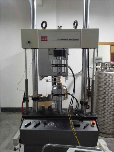
In this paper, one-dimensional quasi-static compression test is carried out with MTS. In the experiment, the alumina ceramic column with a φ30 mm×40 mm was used as the indenter to make the piezoelectric ceramic specimen bear uniform force and avoid the charge loss during loading. The strain measurement and recording of PZT5H piezoelectric ceramics can be directly connected with the dynamic measurement system by an extensometer, and the corresponding values can be output by computer software. In order to extract and collect the charge generated in the loading process, a thin copper sheet is pasted on each side of the two loading heads and connected with the wire, as shown in . The real picture of the static load experiment is shown in .
Figure 1. Schematic diagram of compression loading and testing principle
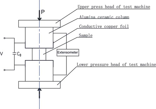
Figure 2. Static load experiment
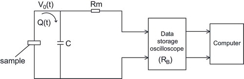
During the whole loading process, the compression load changes uniformly, and the charge is a linear function of time. Therefore, the measurement method of parallel capacitance is adopted [Citation14], the charge mode measurement circuit is shown in . In other words, the sample is connected with a capacitor to form a loop, and the voltage V at both ends of the capacitor is recorded directly by a dynamic measuring system and computer. The electric displacement produced by the quasi-static compression process is as follows:
Figure 3. Measuring circuit of charge mode
2.2.2. Experiments under impact loading
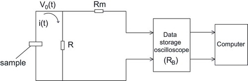
In this paper, a SHPB device with a diameter of 37 mm is used to test the dynamic mechanical properties [Citation15]. The diameter of the bullet, incident rod, and transmission rod are 37 mm. The schematic diagram of the experimental device is shown in , in which the strain gauges are ordinary. The real picture of the impact load experiment is shown in . In the experiment, the lead-out electrode of piezoelectric ceramics is a thin-film electrode, which is a polyimide-based Al-coated electrode with conductivity on one side and nonconductivity on the other, as shown in . Under impact loading, the load is instantaneous and the current is an integral function with respect to time. Therefore, a current mode-measuring circuit of a parallel resistor is used to measure the electrical displacement of the piezoelectric ceramic sample [Citation16], As shown in , where RB is the input impedance of the oscilloscope. In this circuit diagram, the voltage drop at both ends of resistance R is measured to indicate the magnitude of transient current i(t). Then, charge Q(t)can be obtained by integrating i(t) with time, and then the electric displacement can be obtained. Among them, is the matching resistance, which matches the pre-PZT module with the cable impedance, and RB is the input impedance of the oscilloscope. Where
, then
, it can be obtained from :
Figure 4. SHPB device with measuring electric displacement
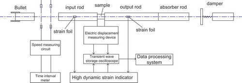
Figure 5. Impact load experiment
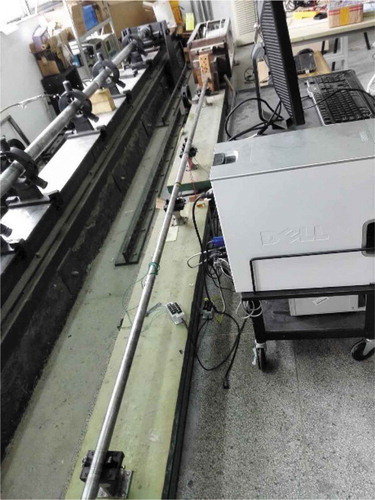
Figure 6. Thin-film electrodes

Figure 7. Measuring circuit of current mode
From and formula (2) to (4), it can be obtained:
According to formulas (4) and (5), charge and displacement can be obtained by a simple transformation of voltage measured by the current method. That is to say, the electric displacement can be obtained from the following:
In the formula, is the area of the sample.
3. Experimental results and analysis
3.1. Quasi-static load experiment results
In this paper, quasi-static compression experiments and analyses are carried out for PZT5H piezoelectric ceramics under different maximum loading loads and different loading stress rate conditions, which includes the relationship between stress and strain, stress, and electric displacement of piezoelectric ceramics.
are stress–strain curves and stress-electric displacement curves of PZT5H under different maximum loading stresses, respectively. Among them, the black curve in indicates that the strain of PZT5H piezoelectric ceramic material changes with its stress when the set maximum loading load is 10 kN. The black curve in indicates that the electric displacement of PZT5H piezoelectric ceramic material changes with its stress when the set maximum loading load is 10 kN. It can be seen from the figures that under the same maximum loading load, both strain and electric displacement increase with increasing stress during the loading phase. With the increase of the stress, the stress–strain curves and the stress – electric displacement curves change from approximately linear to nonlinear and then to linear. From the micro mechanism analysis, the nonlinear characteristics are caused by the microdomain deflection. When the stress exceeds the mechanical coercive stress, the irrecoverable part of the domain deflection strain increases rapidly, which leading to the depolarization failure of the material.
Figure 8. Stress-Strain curves under different maximum loading load
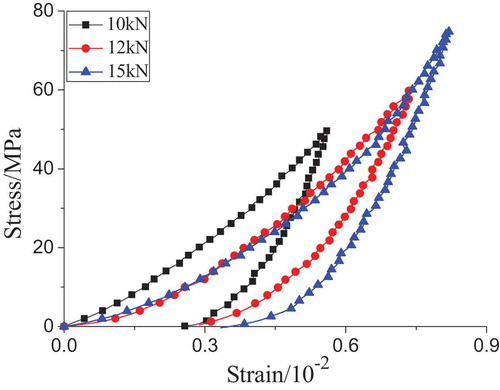
Figure 9. Stress – electric displacement curves under different maximum loading load
The stress–strain curves and stress-electric displacement curves of PZT5H piezoelectric ceramics are shown in , respectively, when different loading stress rates are given under the same maximum loading load conditions. Among them, the red curve in indicates that the strain of PZT5H piezoelectric ceramic material changes with its stress when the given loading stress rate is 1.2 MPa/s. The red curve in indicates that the electric displacement of PZT5H piezoelectric ceramic material changes with its stress when the given loading stress rate is 1.2 MPa/s.
Figure 10. Stress – strain curves under different stress rates
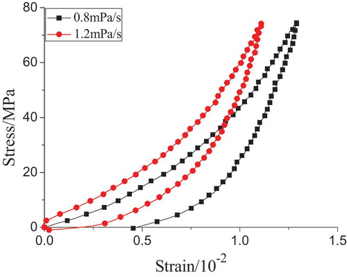
Figure 11. Stress – electric displacement curves under different loading stress rates
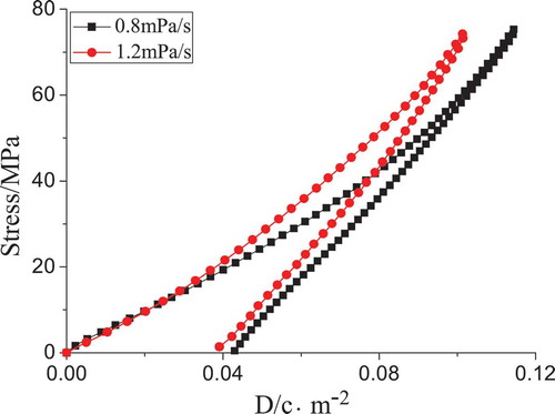
It can be seen from that the stress values corresponding to the same values produced by strain or electric displacement are different with the different loading stress rates. That is, when the piezoelectric materials produce the same strain or electric displacement, the corresponding stress values increase with the increase of loading stress rates.
shows the variation curve of the maximum electric displacement and the loading stress rate produced by PZT5H piezoelectric ceramics under the same maximum loading stress σ = 77 MPa. It can be seen from the figure that the maximum electric displacement of PZT5H piezoelectric ceramics under the first loading increases first and then decreases gradually with the increase of the loading stress rate.
Figure 12. The change of maximum electric displacement with loading rate
3.2. Impact load experiment results
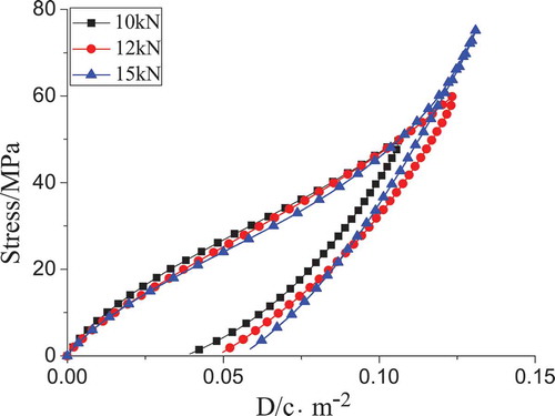
In this paper, a separated Hopkinson pressure bar device (SHPB) is used for the impact load experiment. The results of stress–strain curves and stress-electric displacement of pure PZT5H piezoelectric ceramics under impact loading at different strain rates are shown in , respectively.
Figure 13. Stress–strain curves under different strain rates
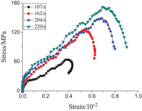
Figure 14. Stress- electric displacement curves under different strain rates
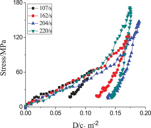
It can be seen from that the corresponding stress value increases with the increase of strain rate at the same strain, and the electric displacement also has the dynamic response characteristic of increasing with the increase of strain rate under the same load.
shows the variation curve between the maximum electric displacement and strain rate of PZT5H piezoelectric ceramics under impact loading. It can be seen from the figure that the maximum electric displacement of PZT5H piezoelectric ceramics increases first and then decreases with the increase of strain rate when the strain rate is less than 220/s.
Figure 15. The relationship of maximum electric displacement and strain rate of PZT5H
In general, domain deflection is a process of changing the direction of domain polarization. When a load is applied outside the piezoelectric crystal, the boundary between the domains inside the crystal is deflected according to the action of the external force, so that the domains in the material also begin to deflect, thereby causing the residual polarization to change. The domain deflection occurs in the piezoelectric crystal due to the application of external force, and the polarization intensity weakens with each other due to the difference of the polarization direction in the adjacent domain area. Therefore, the residual polarization intensity of piezoelectric material also weakens due to the domain deflection in piezoelectric crystal, which leads to the decrease of the piezoelectric properties of piezoelectric material. In the stress–strain curve of piezoelectric ceramics, when the applied load is small, the curve is linear. With the increase of stress and the occurrence of domain deflection, the electric displacement value increases, the residual polarization decreases, and depolarization occurs. This causes the piezoelectric ceramic to gradually lose its piezoelectric properties.
It can be seen from the comparison curves of electric displacement-strain and stress-strain of PZT5H piezoelectric ceramic specimens under impact load. As shown in , the two groups of curves have the same change regulation. The inflection point in the stress – electric displacement time history curves of PZT5H, that is, the point where the slope changes from large to small, is called the G point. There is a good linear relationship before the inflection point. We regard this point as the failure point of PZT5H piezoelectric ceramic under impact load. It is considered that the piezoelectric ceramic has a better electro-mechanical response before reaching the G point. After passing the G-point, piezoelectric ceramics will lose the function that should be achieved. The piezoelectric material gradually fails and damages, and loses its piezoelectric performance.
Figure 16. Stress – electric displacement time history curves of PZT5H
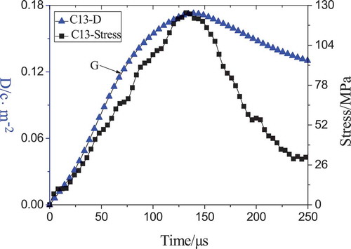
Figure 17. Comparison of stress–strain and electric displacement-strain curves of PZT5H
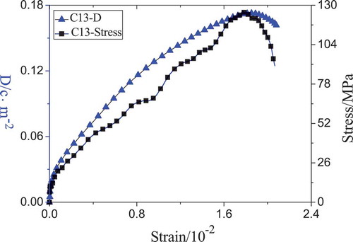
It can be seen from that when the strain rate is less than 220/s, the electrical displacement of PZT5H piezoelectric ceramics increases first and then decreases with the increase of strain rate, and the maximum electrical displacement at the inflection point is about 0.13 .
Figure 18. The curves of the variation of the electric displacement and strain rate in the failure of PZT5H (G Point)
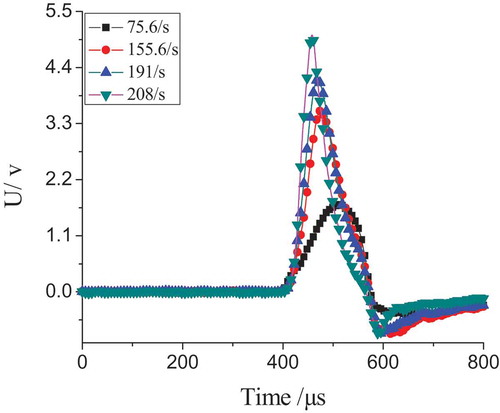
During the process of dynamic loading, the voltage of PZT5H piezoelectric ceramics under different strain rates is analyzed according to the current mode electrical displacement measuring device. The relationship curves of voltage and time were obtained, as shown in . It can be seen from that the response time of the voltage decreases with increasing strain rate [Citation17,Citation18].
Figure 19. Voltage time history curves under different strain rates
4. Conclusion
In the paper, the quasi-static load's experiment and impact load experiments of PZT5H piezoelectric ceramics are studied by using SHPB technology and MTS servo tester. The experimental results are as follows:
(1) Under the same loading stress rate, the corresponding stress values decreases with the increase of the maximum loading stress when the same strain value or the same electric displacement value is produced.
(2) Under the same maximum loading stress, the corresponding stress values increases with the increase of loading stress rates when the same strain value or electric displacement value is produced.
(3) Under impact loading, the response time of PZT5H piezoelectric ceramics decreases with the increase of strain rates. And the electric displacement increases with the increase of strain rate when the impact loads are the same.
(4) Under the impact load, the electric displacement time history curve of the specimen has a similar trend with the stress time history curve, as well as the comparison of the stress-strain curve and the electric displacement–strain curve, which has better electro-mechanical response relationship.
(5) Within a certain range of strain rate, the failure electric displacement of piezoelectric materials under impact loading increase with the increase of strain rates.
Disclosure statement
No, potential conflict of interest was reported by the authors.
References
- Liu Q-Y, Zeng B. Applied research on piezoelectric ceramic in automobile field [J]. Tractor Farm Transporter. 2011;38(3):21–23.
- Guo H, Wang YS, Yang C, et al. vehicle interior noise active control based on piezoelectric ceramic materials and improved fuzzy control algorithm [J]. Appl Acoust. 2019;150(6):216–226.
- Gripp JAB, Rade DA. Vibration and noise control using shunted piezoelectric transducers: a review [J]. Mech Syst Signal Process. 2018;112(9):359–383.
- Yang Z, Zhou S, Zu J. et al. High-performance piezoelectric energy harvesters and their applications [J]. J Books. 2018;2(4):642–697.
- Bowen CR, Arafa MH. Energy harvesting technologies for tire pressure monitoring systems [J]. Adv Energy Mater. 2015;5:1–17.
- Zhang Y, Zheng R, Shimono K, et al. Effectiveness testing of a piezoelectric energy harvester for an auto-mobile wheel using stochastic resonance[J]. Sensors. 2016;16:1727.
- Li Y. Preparation of the PZT-based piezoelectric ceramic and application in the acceleration sensor[D]. Zhengzhou: Zhengzhou University; 2015.
- Allamraju KV, Korla S. Studies on mechanical and electrical characteristics of PZT-5H patch [J]. Mater Today Proc. 2017;4(2):126–132.
- Dongyu X, Shifeng H, Lei Q, et al. Study on the preparation, performance and application of piezoelectric traffic sensors[C]. Proceedings of the Symposium on Chinese Materials Abstracts; 2011.
- Jaitanong N, Yimnirun R, Zeng HR, et al. Piezoelectric properties of cement based/PVDF/PZT composites [J]. Mater Lett. 2014;130(1):146–149.
- Wang S, Liu KX. Experimental research on dynamic mechanical properties of PZT ceramic under hydrostatic pressure [J]. Mater Sci Eng A. 2011;528(21):6463–6468.
- Bao X, Chen Y, Ji H, et al. Review on the preparations of lead zirconate titanate ceramics[J]. J Ceram. 2019;40(2):154–157.
- Qu J, Huang S, Xu Y, et al. Fabrication and properties of PZT piezoelectric ceramic tubes with large length–diameter ratio[J]. Ceram Int. 2014;40(8):13019–13024.
- Yan L. Dynamic measurement technology of PVDF stress meter and its application [D]. ChangSha: National University of Defense Technology; 2004.
- Kariem MA, Santiago RC, Govender R, et al. Round-Robin test of split Hopkinson pressure bar[J]. Int J Impact Eng. 2019;126:62–75.
- Zhidan Z, Song J, Yansong Z. Study on dynamic behavior of PVDF and PZT-5 piezoelectric materials under impact loading[J]. Ordnance Mater Sci Eng. 2008;31(2):65–69.
- Yixuan J. Study on electro-mechanical response and breakdown failure of PZT95/5 ferroelectric ceramics [D]. Lanzhou: Lanzhou University; 2015.
- Dianying W, Qiwen L. Dielectric breakdown of shock wave compressed PZT95/5 ferroelectric ceramics [J]. J High Pressure Phys. 1998;12(3):199–205.