
 ?Mathematical formulae have been encoded as MathML and are displayed in this HTML version using MathJax in order to improve their display. Uncheck the box to turn MathJax off. This feature requires Javascript. Click on a formula to zoom.
ABSTRACT
The aim of this study was to determine the counter body effect on the wear behavior of TiO2-45 Cr2O3 coating. The commercial TiO2-45 Cr2O3 coating powder was deposited onto the surface of the AISI 316 L substrate using the APS method. Dry sliding wear tests were performed with Al2O3 and WC-Co counter body balls under different loads (5 N, 10 N, and 15 N) and reciprocating frequencies (1 Hz, 2 Hz, and 3 Hz). The COF values obtained from the Al2O3 ball were found to be higher than that of the WC-Co ball. In general, increasing load and sliding speed caused higher wear volume values for both counter body balls. When using Al2O3 ball under the 5 N load, a higher amount of wear debris and crack formation was observed, whereas, for higher loads, a larger plastic deformation zone which has lots of pitting and spalling was determined. As for the WC-Co ball, swelling-induced spallation and delamination were recorded as the effective wear mechanisms as well as the plastic deformation.
1. Introduction
AISI 316 L is a well-known type of austenitic stainless steel (SS) and has wide applications ranging from the food processing industry to nuclear reactors. It is commonly used as a standard material for various applications at high-temperature vacuum conditions [Citation1–4]. Since the AISI 316 L SS is subjected to different operating conditions, it is required to maintain its functionality under harsh conditions such as wear, oxidation, and corrosion [Citation1]. In order to protect metals from the mentioned severe environments, coating of component surfaces with ceramics is a frequently used surface modification method to enhance their tribological performance [Citation5–7]. Thermal spraying is the most widely used technique that can be implemented on a variety of ceramics for producing thick coatings.
Chromium oxide (Cr2O3) coating is used as a protective coating material in many engineering applications due to its high resistance to wear, corrosion, and oxidation. However, its fracture toughness is relatively lower than some oxide-content ceramic coatings [Citation8]. Therefore, Cr2O3 spray powder is blended with relatively soft oxide ceramics to increase the toughness of the coating. It was reported in some studies that the addition of titanium oxide (TiO2) to Cr2O3 coating powder resulted in higher fracture toughness and wear resistance [Citation9,Citation10]. Berger et al. [Citation11] studied friction and wear behavior of the Cr2O3-25TiO2 coating under dry sliding wear conditions. They reported that the friction coefficient was decreased with increasing sliding velocity. Li et al. [Citation12] investigated the effect of TiO2 addition in different ratios on friction behavior of the Cr2O3–TiO2 coating.
Thermally sprayed TiO2 coatings have been mostly studied for the components used in biomedical applications to improve the fracture toughness, hardness, and wear resistance of the coating [Citation13–15]. Pure TiO2 is a dense and relatively ductile ceramic coating material. However, in general, it has a lower hardness and less wear resistance than the coatings used for similar purposes. To overcome this problem, a powder composition is prepared by mixing Cr2O3 into the pure TiO2 powder in different mass ratios. In this way, the hardness of the composite coating (TiO2-Cr2O3) is significantly increased, resulting in higher wear resistance [Citation16]. Another point to be considered in determining the wear behavior of ceramic coatings is to fully explain the contact mechanics between the counter body part and the coating. From this point of view, the mechanical properties of the counter body part such as hardness, fracture toughness, and modulus of elasticity have a significant effect on the wear behavior of coating in contact [Citation17].
The TiO2-45 wt.% Cr2O3, a commercial coating powder (Metco™111), is recommended as a wear-resistant coating material for the applications such as mandrels for dry cell battery cores, oil industry sucker rod couplings, drum doctor blades, machine tool chip breakers, and cylinder bore liners [Citation16]. However, there are not enough studies in the literature regarding the wear behavior of TiO2-45 wt.% Cr2O3 coating against different contact surfaces. Therefore, in this study, the wear behavior of TiO2-45 wt.% Cr2O3 coating was investigated using two different counter body parts (Al2O3 and WC-6 wt.% Co) with different hardness, fracture toughness, and elastic modulus values.
2. Experimental procedure
AISI 316 L SS (EN 1.4404) samples were prepared as 25 mm in diameter and 8 mm in thickness. Prior to the deposition process, the substrate samples were grit-blasted and cleaned with acetone to improve the adherence capability of coatings via increasing surface roughness. Grit-blasting parameters are 75° impact angle; 50 mesh SiC particle size; 0.5 MPa blasting pressure and 65–85 mm blasting distance. Commercially available TiO2-45Cr2O3 (Metco 111, −63 + 11 μm) ceramic powders were purchased from Oerlikon Metco. The chemical composition of ceramic powder is given in .
Table 1. Chemical composition (wt.%) of ceramic powder [Citation16]
The deposition of powder onto the AISI 316 L SS substrates was implemented with atmospheric plasma spray (APS) technique using a Metco MCN type control unit via service procurement (Senkron Surface Technologies–Gebze Turkey). Prior to the deposition process, TiO2-45Cr2O3 powder was heated in a furnace at 60°C for 5 h to provide dehumidification, thereby further improving the flowability of the feedstock powder. Deposition parameters used in the APS process are given in .
Table 2. APS deposition parameters applied for the coating process
After the deposition process, the samples prepared for characterization were cut into small pieces with the use of a precision cutting device (Metkon Micracut 152, Turkey) and then cold-mounted. The samples mounted were ground with up to 2500 grit SiC abrasive grinding papers for characterization and microhardness measurements. Microhardness measurements were taken from the coating cross-section with a microhardness tester (Qness Q10, Austria) by utilizing a 500 g (HV0.5) load and 15 s dwell time. Microhardness values for each sample were obtained by taking the average of four measurements.
Microstructure and elemental analyses of the as-prepared and worn coatings were evaluated using scanning electron microscopy (SEM) and EDS (Tescan MAIA3 XMU, Czech Republic). Phase constituents of the coated samples were identified using X-ray diffraction analysis (XRD; Rigaku D/Max-2200VPC, Japan). XRD analysis was carried out with Cu_K-beta radiation produced at 40 kV and 30 mA. The θ-2θ scan was performed between 10º and 90º by a step width of 0.0100º. Porosity measurements of coating layers were made using image analysis software (IMAGE J).
The wear tests were carried out using a ball-o-disc tribometer (Turkyus, Turkey). The values of wear volume were calculated using the data obtained from an optical profilometry device (Huvitz HDS 5800, Republic of Korea). Prior to the wear tests, coated top surfaces of the samples were ground and polished, and ultrasonically cleaned in acetone. Coated samples were subjected to dry sliding wear tests under reciprocating motion in accordance with ASTM standard G133 on a ball-on-disc tribometer at room temperature. The apparatus used in the ball-on-disc tests is equipped with a software and auxiliary hardware that enables recording instantaneously measured frictional forces depending on time by use of a load cell. Each test combination given in was repeated three times to obtain mean and deviation values. After calculation of friction coefficients based on frictional force-time values, the relevant graphs were obtained. To evaluate the wear behavior of TiO2-45Cr2O3 coatings, two different types of counter body balls (WC-Co and Al2O3) with a diameter of 6 mm were used in reciprocating wear tests. Wear test parameters and mechanical properties of the counter body balls are given in and , respectively.
Table 3. Dry sliding wear test results of TiO2-45Cr2O3 coating
Table 4. Dry sliding wear test parameters
Table 5. Mechanical properties of counter body balls used in the wear tests [Citation17]
The values of wear volume were calculated using the data obtained from the optical profilometry device. An exemplary profilometer output showing three-dimensional and cross-sectional views of a worn surface is shown in . As shown in ), the mean value of the cross-section area was automatically calculated by the software of the device from the area measurements ()) taken from the cross-section of the worn track.
Figure 1. Worn track profilometer images used in calculating the wear rates. (a) 3D view (b) cross-section view (c) cross-section area (μm2)
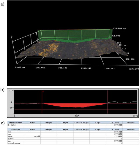
The wear volume and specific wear rate of the TiO2-45Cr2O3 coating were calculated using the following formulas [Citation17].
In the EquationEq.1(1)
(1) and EquationEq.2
(2)
(2) formulas, V(mm3) and K (mm3N−1m−1) stand for the wear volume and specific wear rate, respectively; L (mm) is the stroke length; A (mm2) is the mean cross-sectional area of the wear track; S (m) is the total sliding distance calculated by multiplying of all three values given in (reciprocating frequency f (s−1); stroke length L (mm); and a number of cycles, Nc); and P (N) are the applied normal load.
3. Results and discussion
3.1. Analysis of the coating structure
shows the cross-section SEM image of the as-sprayed TiO2-45Cr2O3 coating. As seen in , the coating layer has a porous structure reflecting the typical characteristics of the APS process [Citation18]. Also, it can be said that the interface region between the TiO2-45Cr2O3 coating layer and the substrate has a smooth and well-adhered structure. The porosity value of the TiO2-45Cr2O3 coating layer was calculated as 6.45 ± 2%. This calculated porosity value was found to be suitable for the porosity range of plasma-sprayed ceramic coatings [Citation19]. From the microhardness measurements, the mean hardness value of TiO2-45Cr2O3 coating was measured as 955 HV0.5.
Figure 2. Cross-section SEM image of as-sprayed TiO2-45Cr2O3 coating
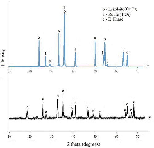
The XRD patterns of TiO2-45Cr2O3 composition for the feedstock powder and APS-sprayed coatings are given in . From the XRD analysis of the feedstock powder, it was determined that chromium titanium oxide phases in the compositions of the (Cr0.88Ti0.12)2O3, Cr0.54Ti0.46O1.73, and Cr2Ti7O17, called E phases, were dominant. Besides, the titanium oxide phases observed in powder content were found to be compatible with the TinO2n-1 composition of the Magnéli phases in the Ti-O phase diagram. As seen in Figure 3.2b, the coating composition is mainly composed of eskolaite, as well as the rutile phase [Citation20].
Figure 3. XRD patterns for TiO2-45Cr2O3 composition (a) powder (b) APS-sprayed coating
3.2. Effect of load on tribological behavior
3.2.1. Worn surfaces
In literature, the crack propagation, removal of transferred films, and splat delamination were reported as predominant wear mechanisms affecting the wear of oxide ceramic coatings [Citation8–10]. shows the SEM images obtained from the wear tests performed under different loads with the Al2O3 ball. In ), it was seen that plastic deformation and delamination type wear occurred predominantly under 5 N load. In addition, there were microcracks formed by the plastic deformation effect on the worn surface. When ) was examined, the delamination effect due to plastic deformation was also observed. As seen in ), with the increase of the load (15 N), the rate of plastic deformation has also increased as a result of high frictional heat on the contact surface. This situation caused a significant increase in the material transfer rate on the coating surface and as a result, the transferred layers provided the formation of tribolayer with low roughness.
Figure 4. Worn surface SEM micrographs obtained using Al2O3 ball under different loads a1) 5 N b1) 10 N c1) 15 N (magnification 500x); 2) represents higher magnification (2kx) for corresponding images
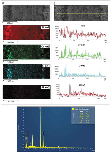
shows the EDS images which are taken from the worn surface track obtained using Al2O3 counter body ball. In ), images of elemental data obtained by the EDS area mapping method are given. According to these images, Ti, Cr, and O elements are available in accordance with the coating composition. Also, the presence of Al has been determined, and it is thought that these are the wear debris particles removed from the Al2O3 counter body ball as a result of wear. Another proof of this situation is the presence of Al, which increases throughout the width of the wear track in the transverse line scanning taken over the worn surface given in ).
Figure 5. Worn surface EDS images obtained using Al2O3 counter body ball. (load: 15 N; sliding frequency: 3 Hz) (a) area mapping (b) line scanning
shows the worn surface images formed under 5 N, 10 N, and 15 N loads with WC-Co ball. When the worn surfaces given in and are compared, it should be noted that the worn surface images obtained with the WC-Co ball are smoother under the same test conditions. This situation can be explained from two different points of view. The first is that when is examined, the WC-Co ball is harder, stiffer, and tougher than the Al2O3 ball. So, these advantages ensure relatively less wear occurred on the WC-Co ball in comparison to the Al2O3 ball. In addition, this case provides an increase in wear-induced plastic deformation ratio of the coating resulting in a smooth surface with low COF value. On the contrary, the lower hardness and fracture toughness values of the Al2O3 ball caused its wear due to the hard Cr2O3 content in the coating. Thus, with the effect of mutual wear of the ball and coating, two-body and three-body wear mechanisms emerged and caused the contact surface to become rougher. Secondly, it can be explained by the use of Hertzian contact mechanics that considers the contact radius calculated from the values of elastic modulus and Poisson ratio (see section 3.3.2).
Figure 6. Worn surface SEM micrographs obtained using WC-Co ball under different loads (a) 5 N (b) 10 N c) 15 N (magnification: 500x); 1) represents higher magnification (2kx) for corresponding images
Another point is that, as seen in ), the crack formation under 5 N is on a small scale and spread over the surface, and also there is a large number of wear debris. In the literature, it is reported that if the load reaches a critical level, lateral cracks will begin from the plastic deformation zone and then progress rapidly, causing brittle fracture resulting in the removal of the material [Citation21]. Bagde et al. studied on friction and wear behavior of the plasma-sprayed Cr2O3-25TiO2 coating [Citation8]. They stated that the increase in abrasive wear rates depending on the load was observed as grain pullout caused by fatigue induced microcracks at low loads and as delamination cracks and splat fractures at high loads. In ), it is observed that the depth and length of the cracks increased and swelling occurred due to the plastic deformation effect. With the 15 N load, plastic deformation predominantly led to spallation and became prominent in volume losses ()).
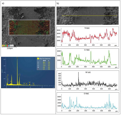
In ), EDS area mapping data obtained from the worn surface track created with the WC-Co counter body ball is given. Similar to ), the Ti, Cr, and O elements are present and in addition W and C have also been detected and these are the wear-induced particles removed from the WC-Co counter body ball. This is also confirmed by the presence of W, which increases with the width of the wear track in the transverse line scanning taken over the worn surface given in ).
Figure 7. Worn surface EDS images obtained using WC-Co counter body ball. (load: 15N; sliding frequency: 3Hz) (a) area mapping (b) line scanning
3.2.2. Friction and wear
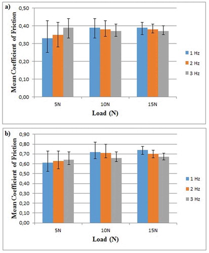
As seen in , a significant difference was observed between the coefficient of friction (COF) values recorded with Al2O3 and WC-Co balls. In general, according to , the COF values of the Al2O3 ball are higher than those obtained with the WC-Co ball for all loads. If the COF values obtained with the Al2O3 ball were examined first, the average of the friction coefficient increased during the first 2 min from the start of the test and after that it passed to the steady-state. This situation can be attributed to initial wear of the coating emerging during the running-in period by the initial deformation or fracturing of the high asperities, which renders the contacting surfaces mate better, which further results in higher COF values.
Figure 8. COF graphs of TiO2-45Cr2O3 coating under different loads and counter body balls
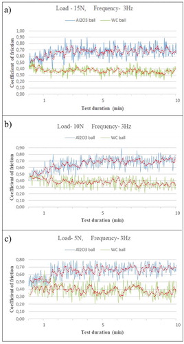
In the COF plots taken with the Al2O3 ball, the average COF value was recorded as approximately 0.7 with no significant fluctuation under 15 N load. The COF values decreased to a level of 0.65 with a decrease of approximately 5% in 5 N load. In ), according to the COF graphics obtained from the WC-Co ball, it can be seen that the fluctuation becomes evident with the decrease of the load. In general, there was no significant change in the COF values recorded with the WC-Co ball during the test and the average COF value was 0.4. This value is approximately 45% lower than the COF value received with the Al2O3 ball. A major reason for obtaining higher COF values with Al2O3 ball is the high roughness values of the worn surface caused by the wear mechanisms that affect the contact area.
As is known, the wear is closely related to the values of hardness and fracture toughness in oxide-content ceramic coatings [Citation22–25]. In this context, it has been observed that the differences among the values of hardness, stiffness, and fracture toughness of counter body balls play a key role in the wear behavior of the coating, especially in tests with the Al2O3 ball. In , a schematic illustration of the change of wear mechanisms between the coating surface and the Al2O3 ball over the test time is shown. After the wear tests, significant wear marks were detected according to the examinations made on the contact surface of the Al2O3 ball (). The contact surface of the WC-Co ball was less worn in comparison to the Al2O3 ball due to its high hardness, stiffness, and toughness. Besides, it was observed that the abrasion occurred mostly on the surface of the coating and so, the contact surface remained in a limited area resulting in a relatively small wear rate overall. On the other hand, as seen in , the worn surface area observed on the Al2O3 ball has enlarged depending on the load. By the combined effect of enlarged contact area and increased surface asperity, the Al2O3 ball caused to a higher amount of wear volume loss than that of WC-Co ball (as seen in )). As seen in , the worn track profile created with the Al2O3 ball is deeper and wider than that of the WC-Co ball.
Figure 9. Schematic illustration of the change of wear mechanisms between the coating surface and the Al2O3 ball over the test time
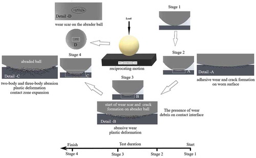
Figure 10. Optical profilometer images of worn surface counterparts under different loads (Frequency: 3 Hz) (a) 15 N, (b) 5 N, a1) and b1) represent top views of Al2O3 ball; a2) and b2) corresponding counterpart top views of the coating; a3) and b3) cross-section views of worn track
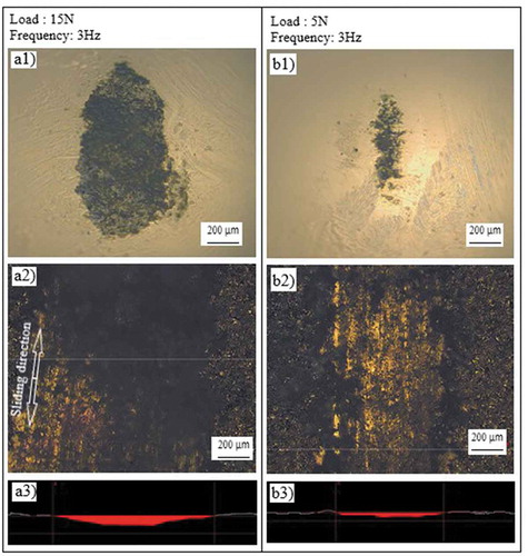
Figure 11. Worn surface images of TiO2-45Cr2O3 coating under different loads and counter body balls (a) Al2O3 ball (b) WC-Co ball
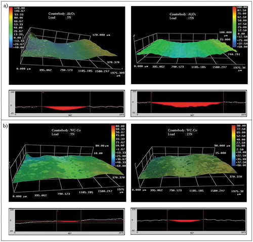
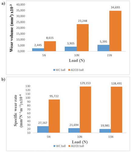
Figure 12. Mean values of the wear results of TiO2-45Cr2O3 coating under different loads and counter body balls (frequency: 3 Hz) (a) wear volume loss (b) specific wear rate
The stresses and deflections arising from the contact between two elastic solids have practical application in the wear behavior of engineering ceramics [Citation26]. It was declared by Hertz [Citation27] that in case of contact between a rigid sphere and a flat surface, the radius of the circle of contact is related to the indenter load, the indenter radius, and the elastic properties of the materials [Citation26–29].
The maximum tensile stress that leads to crack initiation and progression occurs at the edge of the contact circle is given by EquationEq.3(3)
(3) [Citation26]:
where a is the radius of the circle of contact and P and ν are the indenter load and Poisson’s ratio of the indenter, respectively.
EquationEq.3(3)
(3) can be rewritten as follows:
where E* is the combined modulus of the indenter and the specimen and Ri is the radius of the indenter.
Considering the values given in , the E* value will be higher for WC-Co ball using the related calculating formula [Citation29]. So, in the case of using a WC-Co ball, a smaller contact radius, and consequently higher maximum tensile stress will occur than that of Al2O3 ball according to EquationEq. 3(3)
(3) . In other words, the maximum stress that ultimately affects plastic deformation is inversely proportional to the contact radius. This situation confirms the predominance of the plastic deformation occurring under the WC-Co ball and is compatible with worn surface images given in . Since the load is constant during the wear test in this study if the contact radius enlarges the nominal stress will also decrease proportionally.
The results of dry sliding wear tests carried out on TiO2-45Cr2O3 coating are given in Table 3.1. When the specific wear rate values obtained with the Al2O3 ball were examined, the value increased to 129,153x10−6 (mm3N−1m−1) with an increase of 36%, as the load increased from 5 N to 10 N (). However, the same situation showed a decrease of approximately 0.7% under the 15 N load with the opposite effect for the reasons mentioned earlier.
3.3. Effect of sliding speed on tribological behavior
3.3.1. Worn surfaces
In , the worn surface SEM images which are taken after the wear tests performed under different values of load and sliding speed using Al2O3 ball are given. As seen in , with the increasing load and sliding speed, the rate of plastic deformation on the surface increased and the formation of tribolayer became evident. It can be said that this case supports the data given in and the analysis regarding the decrease of COF values. shows the worn surface images after abrasion tests with WC-Co ball. As seen in , surface asperity caused by wear increased with increasing sliding speed at 5 N load and this was compatible with the COF values given in . Besides that, at 10 N and 15 N loads, it was observed that the amount of plastic deformation increased with increasing sliding speeds, resulting in swelling and spallation zones and a smoother surface with a lower COF value than that of the 5 N load on other contact surfaces.
Figure 13. Worn surface morphologies taken after the wear tests carried out with Al2O3 ball at different sliding speeds and loads (magnification: 500x, f: reciprocating frequency)
Figure 14. Worn surface morphologies taken after the wear tests carried out with WC-Co ball at different sliding speeds and loads (magnification: 1000x, f: reciprocating frequency)
Figure 15. Mean COF value vs. sliding speed (reciprocating frequency) under different loads and counter body balls (a) WC-Co ball (b) Al2O3 ball
3.3.2. Friction and wear
In , the average COF values depending on the sliding speed were given separately for each load and counter body ball. When was examined, the average COF values obtained under 5 N for both counter body balls increased with increasing sliding speed (reciprocating frequency). However, under 10 N and 15 N loads, the amount of plastic deformation increased with the increasing sliding speed, and tribolayer formation with lower roughness occurred, thus reducing the average COF values. Berger et al. [Citation11] pointed out a similar result stating the friction coefficient decreased with increasing sliding velocity. At low load (5 N), since the plastic deformation rate was low, the smooth surface formation was limited resulting in a high average value of COF. In the literature [Citation30,Citation31] it was specified that the friction coefficient increased with the increase of the sliding speed when Si4N3 counter body balls were used against the stainless steel, which is in agreement with the results obtained under 5 N load in this study. However, in another study, it was noted that inconsistent COF values with each other were obtained from the wear tests carried out with counterparts having different hardness [Citation32].
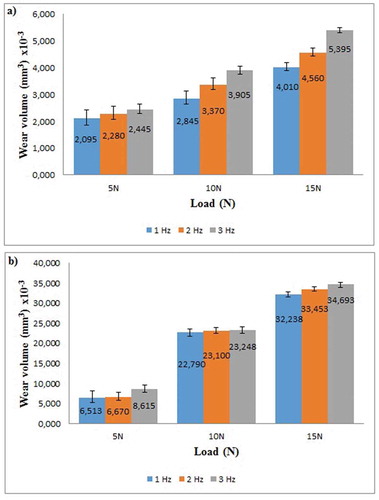
shows the change of wear volume loss values obtained with Al2O3 ball and WC-Co ball according to reciprocating frequency. Accordingly, it was seen that the wear volume losses obtained with both Al2O3 ball and WC-Co ball tend to increase with increasing sliding speed. In ), with the WC-Co ball, the values obtained at a frequency of 1 Hz under a load of 5 N increased approximately by 9% at 2 Hz, while this frequency increased by 7% when the frequency was 3 Hz. The same trend continued under 10 N load and the increasing percentage was calculated as 18% with the sliding speed increasing from 1 Hz to 2 Hz. At 3 Hz, this increase was found to be approximately 15% compared to 2 Hz. At the highest load value (15 N), increases in volume loss calculated according to speeds were 13.7% (from 1 Hz to 2 Hz) and 18.3% (from 2 Hz to 3 Hz), respectively. In the tests with the Al2O3 ball ()), it was determined that increase in the reciprocating frequency caused to increase in the volume loss values, but this increase was much lower than that of the WC-Co ball. In experiments under 10 N and 15 N loads, the increase in volume loss values according to the sliding speeds at which from 1 Hz to 2 Hz and 2 Hz to 3 Hz were calculated as approximately 1% and 3%, respectively.
Figure 16. Variation of wear volume loss according to sliding speed and load with different counter body balls (a) WC-Co ball (b) Al2O3 ball
4. Conclusions
The TiO2-45Cr2O3 is recommended as a wear-resistant coating material for the applications such as mandrels for dry cell battery cores, oil industry sucker rod couplings, drum doctor blades, machine tool chip breakers, and cylinder bore liners. It is clear that the application areas of this coating material are in a wide variety of operating conditions. Therefore, the part surfaces coated with TiO2-45Cr2O3 will inevitably be subject to wear as a result of friction with different contact surfaces. In contact mechanics, it is known that the mechanical properties of the counter body part, such as hardness, fracture toughness, and modulus of elasticity, have a significant effect on the wear behavior of the parts in contact. Thus, this study was carried out to determine and compare the wear behavior of TiO2-45Cr2O3 coating in contact with ceramic (Al2O3) and cermet (WC-Co) counter body balls. According to the test results, it has been determined that the counter body material in contact has a significant effect on the wear behavior of the mentioned coating. The main conclusions are as follows:
• In general, increased load and sliding speed caused an increase in volumetric wear loss values for both counter body balls. It was determined that the volumetric wear loss values obtained with the Al2O3 ball were several times higher than that of the WC-Co ball. However, the effect of an increase in load and sliding speed on volumetric wear loss was lower in Al2O3 ball than WC-Co ball.
• The COF values obtained from the Al2O3 ball were significantly higher than that of the WC-Co ball. This situation was attributed to a higher amount of abrasion which was occurred in the contact zone of the Al2O3 ball compared to the WC-Co ball.
• It was observed that the effect of the load on the wear mechanisms affecting the tribological performance of the TiO2-45Cr2O3 coating was significantly different for the WC-Co ball and the Al2O3 ball. When using Al2O3 ball under the 5 N load, it was observed that the plastic deformation was at low rates and mostly consisted of wear debris and crack formation. Under 10 N and 15 N loads, the rate of plastic deformation increased, leading to an increase in the contact surface area. As a result, it was observed that a larger deformation zone with many pitting and spalling zones occurred. As for the WC-Co ball, plastic deformation was commonly observed for all test conditions. Swelling-induced spallation and delamination were the predominant wear mechanisms that occurred on the worn surface. It was seen that the plastic deformation rate increased with increasing load and sliding speed. Increased sliding speed resulted in a higher rate of spallation on the worn surface. Another finding is that the formation of the tribolayer is increased significantly with the combined effect of increasing load and sliding speed.
Acknowledgments
This study was financially supported by TUBITAK (The Scientific and Technological Research Council of Turkey) with the project no: 113M178.
Disclosure statement
No, potential conflict of interest was reported by the author.
Additional information
Funding
References
- Saravanan M, Devaraju A, Venkateshwaran N, et al. A review on recent progress in coatings on AISI austenitic stainless steel. Mater Today. 2018;5:14392–14396.
- Smith AF. The sliding wear of 316 stainless steel in air in the temperature range 20–500°C. Tribol Int. 1985;18:35–43.
- Devaraju A, Elayaperumal A, Venugopal S, et al. Investigation on the high vacuum tribological characteristics of surface treated nuclear grade stainless steel type AISI 316LN at 25°C −500°C. Stroj Vestn-J Mech E. 2011;57:927–935.
- Devaraju A, Elayaperumal A, Alphonsa J, et al. Sliding wear behavior of plasma nitrided austenitic stainless steel type AISI 316LN in the temperature range from 25 to 400 °C at 10−4 bar. Wear. 2012;288:17–26.
- Chen Y, Wu D, Ma G, et al. Coaxial laser cladding of Al2O3-13%TiO2 powders on Ti-6Al-4V alloy. Surf Coat Technol. 2013;228:S452–S455.
- Mahamood RM, Akinlabi ET. Chapter 21 – laser-assisted additive fabrication of micro-sized coatings A2 – lawrence, jonathan, advances in laser materials processing. 2nd ed. U.K.: Woodhead Pub; 2018. p. 635–664.
- Karthikeyan J, Mayuram MM. Ceramic coating technology. Sadhana. 1988;13(1):139–156.
- Bagde P, Sapate SG, Khatirkar RK, et al. Friction and wear behaviour of plasma sprayed Cr2O3-TiO2 coating. Mater Res Express. 2018;5(2):026410.
- Fernlindez JE, Wang Y, Tucho R, et al. Friction and wear behavior of plasma-sprayed Cr2O3 coatings against steel in a wide range of sliding velocities and normal loads. Tribol Int. 1996;29(4):333–343.
- Yinglong W, Yuansheng J, Shinzhu W. The analysis of the friction of wear mechanisms of plasma sprayed ceramic coatings at 450°C. Wear. 1988;128:265–276.
- Berger L-M, Stahr CC, Saaro S, et al. Dry sliding up to 7.5 m/s and 800°C of thermally sprayed coatings of the TiO2-Cr2O3 system and (Ti,Mo)(C,N)–Ni(Co). Wear. 2009;267:954–964.
- Li N, Li G, Wang H, et al. Influence of TiO2 content on the mechanical and tribological properties of Cr2O3-based coating. Mater Des. 2015;88:906–914.
- Alvarez-Vera M, Hdz-García HM, Muñoz-Arroyo R, et al. Tribological study of a thin TiO2 nanolayer coating on 316L steel. Wear. 2017;376-377:1702–1706.
- Lima RS, Marple BR. Enhanced ductility in thermally sprayed titania coating synthesized using a nanostructured feedstock. Mater Sci Eng. 2005;A 395(1):269–280.
- Forghani SM, Ghazali MJ, Muchtar A, et al. Mechanical properties of plasma sprayed nanostructured TiO2 coatings on mild steel. Ceram Int. 2014;40(5):7049–7056.
- Oerlikon metco thermal spray materials guide, issue. April 2017.
- Küçük Y. Effect of counter body on the dry sliding wear performance of plasma-sprayed calcia-stabilized zirconia coating. Int J Refract Metals Hard Mater. 2020;92:105284.
- Padture NP. Thermal barrier coatings for gas-turbine engine applications. Science. 2002;296(5566):280–284.
- Wang H-D, He P-F, Ma G-Z, et al. Tribological behavior of plasma-sprayed carbon nanotubes reinforced TiO2 coatings. J Eur Ceram Soc. 2018;38(10):3660–3672.
- Berger L-M, Saaro S, Stahr CC, et al. Development of ceramic coatings in the Cr2O3-TiO2 system. Therm Spray Bull. 2009;61(1):64–77.
- Evans AG. Report No. LBL-8608, national bureau of standards-ceramic meeting. Gaithersburg, Washington: Abrasive wear in ceramics: an assessment; 1978.
- Akagaki T, Kato K. Effects of hardness on the wear mode diagram in lubricated sliding friction of carbon steels. Wear. 1990;141:11–15.
- Gore GJ, Gates JD. Effect of hardness on three very different forms of wear. Wear. 1997;203-204:544–563.
- Shipway PH, Wood AH, Dent AH. The hardness and sliding wear behaviour of a bainitic steel. Wear. 1997;203-204:196–205.
- Krawiec S, Le śsniewski T. Correlation between material hardness and its tribological properties. Tribol. 2002;4:in Polish.
- Fischer-Cripps AC. Introduction to contact mechanics. second ed. New York: Springer Science+Business Media, LLC.; 2007.
- Hertz H. On the contact of elastic solids, J. Reine Angew. Math. 92, 1881, pp.156–171. Translated and reprinted in English in Hertz’s Miscellaneous Papers. London: Macmillan & Co.; 1896. p. Ch. 5.
- Tewari A, Basu B, Bordia RK. Model for fretting wear of brittle ceramics. Act Mater. 2009;57:2080–2087.
- Johnson KL. Contact Mechanics. Cambridge, U.K.: Cambridge University Press; 1985.
- Zhang YZ. Dry tribology of materials. first ed. Beijing: Science Press, Beijing; 2007.
- Zhang Z, Li X, Almandoz E, et al. Sliding friction and wear behaviour of Titanium-Zirconium-Molybdenum (TZM) alloy against Al2O3 and Si3N4 balls under several environments and temperatures. Tribol Int. 2017;110:348–357.
- Tang L, Gao C, Huang J, et al. Dry sliding friction and wear behaviour of hardened AISI D2 tool steel with different hardness levels. Tribol Int. 2013;66:165–173.