
 ?Mathematical formulae have been encoded as MathML and are displayed in this HTML version using MathJax in order to improve their display. Uncheck the box to turn MathJax off. This feature requires Javascript. Click on a formula to zoom.
ABSTRACT
Solid oxide fuel cells (SOFCs) offer numerous advantages in terms of high efficiency and clean electrochemcial energy conversion devices. However, owing to high operation temperature, this technology is restricted to stationary applications and leads to components degradation and long-term stability issues. The development of new design and their modifications for improving the electrochemical performance at intermediate temperatures and durability of the SOFC components are very important to bring this technology one step closer to the market. In this context, the current research on the development, properties, performance, and stability of geometrically modified flat-tubular (FT) SOFC cell and the stack is reviewed in detail. This advanced design exhibits higher performance compared to the tubular type and longer stability in comparison to the planar type SOFCs. The application of the interconnect material is emerging as the key factor influencing the electrical output of the FT-SOFC and operation at high temperatures and current density are the critical issues for cell durability. New stack designs are discussed in detail and experimental findings are summarized.
1. Introduction
The high consumption of fossil fuels is increasing the concentration of CO2 in the atmosphere, which is considered to be the major cause of global warming and climate change and ultimately the environmental degradation [Citation1,Citation2]. The utilization of these resource-limited fossil fuels into the clean and highly efficient form of energy has acquired significant attention in the development of advanced energy technologies with negligible environmental impact. In this regard, solid oxide fuel cells (SOFCs) offer the tremendous potential of delivering high electrical efficiency and substantial environmental benefits in terms of fuel flexibility, cleanest and highly efficient power generation [Citation3–5]. A SOFC produces electricity by an electrochemical combination of the fuel and oxidant through an ion-conducting solid ceramic which acts as an electrolyte and operates at high temperatures (~600-1000°C) [Citation6,Citation7]. The high-temperature operation permits internal reforming, promotes rapid electro-catalysis, and results in high-quality heat as a by-product, which can be further utilized. The efficiency of the SOFC can reach up to 70% and a further 20% as a heat recovery [Citation3,Citation8]. Despite the clear advantages, the commercialization of SOFC technology has not entirely succeeded due to this being a high-temperature operation, cost (especially the sealing and current collection materials), and materials degradation issues. Recently, attention has focused on reducing the operating temperature of the SOFCs and developing high-performing and stable devices [Citation9–13].
1.1. Working principle of the SOFC
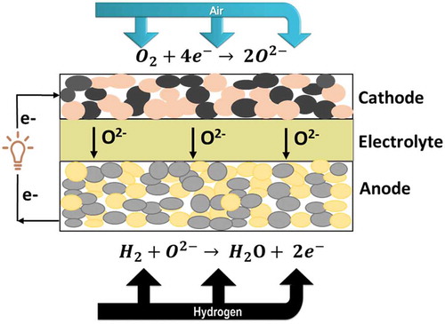
A SOFC unit comprises three basic components: porous fuel electrode (anode), porous air/oxygen electrode (cathode), and a dense solid oxide electrolyte sandwiched between these two electrodes as shown in [Citation6,Citation14,Citation15]. A metallic interconnect is required for the electron conduction and to connect the unit cells into stacks [Citation16]. Hydrocarbons or hydrogen-rich fuels are supplied to the anodic side of the SOFC, where they are oxidized and release electrons, a process known as fuel oxidation reaction (FOR) [Citation17]. The electrons produced during the oxidation of fuel are conducted by the current collector placed on the anode to an external circuit. The cathode is supplied with air or pure oxygen (O2) and converts O2 into O2-, a process known as oxygen reduction reaction (ORR). Since hydrogen (H2) gas is commonly used as a fuel on the anode side and the air is fed as an oxidant on the cathode side,; therefore,the associated chemical reactions at the anode and cathode are as follows:
At the anode, steam forms, according to the following reaction:
The partial pressure of oxygen or oxide ions concentration gradient or oxygen chemical potential across the electrolyte offers the driving force for above mentioned electrochemical processes. The theoretical reversible voltage
) of the SOFC can be given by Nernst equation [Citation18]:
where is the general gas constant,
is the temperature,
represents the number of electrons and
is the Faraday’s constant.
The actual SOFC voltage is always less than the theoretical Nernst value due to the polarization or electrochemical losses. It includes the charge transfer or activation polarization, Ohmic resistance, and concentration polarization. Activation polarization is countered during the charge transfer between electronic and ionic conductors. Nonetheless, when the current density is considerably low and can be approximated as [Citation18]:
Here, is the exchange current density and
refers to intrinsic charge transfer resistance limited to the specific interface of electrode and electrolyte [Citation19]. Ohmic polarization arises due to the resistance in the conduction of oxygen ions in a solid electrolyte and lastly, concentration polarization is because of the mass transport limitation in the cell. In other words, when reacting species are consuming at a fast rate or product evacuation is slow. These losses, however, cannot be completely mitigated but can be minimized with proper materials selection and optimized design and/or fabrication techniques.
Figure 1. Schematic representation of the working principle of the SOFC
1.2. Materials for the SOFC
The present section summarizes the different materials and general requirements for the major SOFC components such as the anode, cathode and electrolyte.
1.2.1. Anode materials
The electrochemical oxidation of the fuel takes place at the anode, preferentially at an area of the surface where electrode, electrolyte, and pore/gas coexist simultaneously. This site is referred to as the triple-phase boundary (TPB). A material, to act as a potential anode must possess an electrical conductivity of more than 100 Scm−1 at the aforementioned SOFC operating temperatures [Citation20,Citation21]. Therefore, nickel (Ni) cermet such as Ni-yttria stabilized zirconia (Ni-YSZ) is the promising anode material with numerous advantages: enhanced catalytic activity for H2 oxidation, high electronic conductivity (102–104 Scm−1 at 1000°C), and reasonable ionic conductivity. In a porous Ni-YSZ anode, the metal phase provides a catalytic activity and electronic conduction while the ceramic phase serves as the backbone and matches the thermal expansion coefficient with the electrolyte, thus extending the reaction zone [Citation22]. However, Ni cermet anode suffers from structural instability during the long-term operation. This is owing to the agglomeration of the Ni particles which reduces the TPB length responsible for the electrochemical reaction [Citation23–25]. Moreover, this anode material exhibits redox instability and coking problem when altering the fueling environment to hydrocarbons. Redox instability is caused by an interruption in fuel supply to the SOFC anode which leads to the oxidation of Ni to NiO. The oxidation of Ni can also occur if fuel utilization or partial pressure of H2O increases on the anode side and causes a volume expansion of 69.9% [Citation22,Citation26]. This phenomenon results in stress development, an increase in the polarization resistance of the SOFC anode, and eventually mechanical failure [Citation26–28]. On the other hand, during the SOFC operation with hydrocarbon fuel, carbon particles settle on the Ni particles of Ni-YSZ anode and hinder the active electrochemical sites and cause performance degradation. This degradation process is termed coking [Citation22,Citation29,Citation30].
Other anode materials such as Cu-Sm doped ceria (SDC) composite are given considerable attention,; however,it was concluded that Cu has less catalytic activity toward the hydrocarbon fuels. Furthermore, perovskite-based materials like La-doped SrTiO3 (LST) have been investigated in detail but exhibited relatively low electronic conductivity as compared to Ni cermet anodes. The research and development of the new anode materials are continuing and their progress is discussed in detail in [Citation18,Citation31].
1.2.2. Electrolyte materials
An electrolyte is the key component of the SOFC which conducts the ions from the cathode to the anode and accomplishes the overall electrochemical reaction [Citation32]. The conduction of oxide ions takes place by an oxygen vacancy mechanism, which is usually a thermally activated process. The main requirements for the electrolyte are: sufficiently high ion conductivity (~0.1 Scm−1), low electronic transfer number (<10−3), chemically and thermodynamically stable over a SOFC operation temperature range, high mechanical strength, and compatible TEC with other component layers [Citation18].
Yttria-stabilized zirconia (YSZ) is recognized as the most favorable electrolyte material for the SOFC due to the characteristics mentioned earlier. Among various electrolytes, 8 mol% YSZ (8YSZ) exhibits the highest oxide ion conductivity of 0.1 Scm−1 at 1000°C. Moreover, numerous other doped zirconia systems, scandia stabilized zirconia (SSZ) exhibits around 1.5 times higher ionic conductivity than the 8YSZ and has received considerable attention [Citation33,Citation34]. Other materials, such as bismuth oxide (Bi2O3) exhibit significantly high ionic conductivity but suffers from structural instability upon cooling below 600°C [Citation35–37]. Ceria-based oxide ion conductors, including Gd-doped ceria (GDC) or SDC, are also potential candidates for electrolyte materials but they become partially reduced on the anode side of SOFC and hence cannot be used alone [Citation38]. Another possibility is to use Sr or Mg-doped LaGaO3 (LGSM) perovskites, which are currently the most promising materials [Citation39,Citation40]. However, their long-term stability needs to be assessed, thus, YSZ or SSZ is the current choice of electrolyte material for the SOFC.
1.2.3. Cathode materials
The most important requirements for the cathode are the electro-catalytic activity for O2 reduction and compatibility toward the electrolyte material, including TEC match and chemical inertness. Platinum was used as one of the earliest materials for oxygen electrodes in SOFCs [Citation41]. However, the high cost strongly limited its range of applications. A porous perovskite-based electronic conductor, lanthanum strontium manganite ((La, Sr) MnO3; LSM) was the most commonly used cathode material because of the superior chemical stability. However, LSM exhibits poor performance at reduced temperatures as it is primarily an electronic conductor with nearly zero ionic conductivity [Citation42,Citation43]. Consequently, they only allow oxygen reduction reactions near TPBs. However, cobaltite perovskite-type oxide materials such as La0.6Sr0.4Co0.8Fe0.2O3−δ (LSCF) or Ba0.5Sr0.5Co0.2Fe0.8O3−δ (BSCF) are mixed ionic and electronic conductors (MIECs) and exhibit a significantly higher electrocatalytic activity for the O2 reduction in comparison to LSM-based cathode [Citation44]. The chemical formula of perovskite oxide is ABO3, where A and B represent two different types of cations. Characteristic A-site cations include alkaline earth ions and rare earth metal ions whereas B-site cations are transition metal ions [Citation45]. Numerous perovskite-like derivatives, such as Ruddlesden–Popper (RP) phases and double perovskite oxides are also extensively studied as potential cathode materials for SOFCs because of their structural features promoting fast electron transfer [Citation46,Citation47].
It is well-known that (La, Sr)(Co, M)O3 (i.e. M = Fe, Mn, eetc. cobaltite-based perovskite electrode materials tend to react with YSZ electrolyte and results in the formation of insulating phases such as La2Zr2O7 (LZO) and/or SrZrO3 (SZO) [Citation48]. Therefore, GDC or SDC interlayers are practically being used in the SOFCs to avoid the undesirable interaction between the cathode and electrolyte [Citation48–51]. Numerous studies revealed that the GDC or SDC interlayer enhances the electrochemical performance of the SOFC owing to higher ionic conductivity [Citation52]. Besides this, cations surface segregation, such as Sr, of the perovskite-based SOFC cathodes is a well-known degradation phenomenon [Citation45]. The chemical environment of cations on the surface of the perovskite-based cathode materials could be different from that within the lattice. Both A- and B-site cations in perovskite-based oxide materials can segregate to the surface and can separate out, leading to the formation of secondary phases at the surface which is insulating in nature [Citation53,Citation54]. This degradation phenomenon reduces the electrocatalytic activity and durability of the cathode material [Citation45].
1.3. Configurations of the SOFC
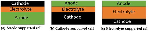
shows various structural configurations of the SOFCs including anode, cathode, and electrolyte supported. However, SOFCs designs are mainly focused on a thin electrolyte film coated on a porous electrode or metallic substrate due to the preference of high-power density at a lower operating temperature [Citation55–57]. However, between electrode supported, anode supported type SOFCs are given high consideration due to the lower polarization and superior electrochemical performance [Citation58–60]. Electrolyte supported SOFCs exhibit low power density due to the higher Ohmic resistance of the stabilized zirconia electrolyte, and therefore are not widely used [Citation61–63].
Figure 2. Various configurations of the SOFCs
1.4. Types of the SOFC
From a geometrical point of view, the SOFC substrate can be mainly classified into tubular type, planar type, and single bbody-typegeometry. However, tubular and planar type SOFCs are widely studied [Citation64–67]. ) displays the schematic diagram of the very well-known tubular-type SOFC. In this type of SOFC, the substrate or support is generally made up of the porous electrode produced via the extrusion process. The electrolyte, reaction barrier layer, and the other electrode material are then coated onto the extruded support, simultaneously [Citation68]. Tubular type SOFCs have several distinct advantages: convenient stacking, resistance to thermal stress, and higher mechanical strength [Citation64]. However, tubular SOFCs have the disadvantages of less power density in comparison to planar type SOFCs and relatively high production costs [Citation69].
) displays the schematic design of the planar type SOFC. A planar type SOFC resembles the sandwich-type geometry where the electrolyte is sandwiched between two porous electrodes. The planar type SOFCs produce higher current density compared to tubular SOFCs and are relatively easy to fabricate. However, demerits include unstable sealing, resulting in fuel and oxidant leakage, poor thermal cycling stability, and relatively high production cost [Citation70–72]. Therefore, a geometrically modified SOFC design is in need which should exhibit a high-power density, thermal robustness, fast start-up and shutdown, easy high-temperature sealing, and interconnect fabrication.
Figure 3. Schematic diagrams of (a) tubular and (b) planar type geometries of the SOFCs. Reproduced with permission from [Citation94]
![Figure 3. Schematic diagrams of (a) tubular and (b) planar type geometries of the SOFCs. Reproduced with permission from [Citation94]](/cms/asset/a2125e2a-e0a3-4771-83eb-2c78767637a6/tace_a_1920135_f0003_oc.jpg)
1.5. Geometrically modified flat-tubular SOFC
shows the schematic design of the geometrically modified flat-tubular (FT) SOFC which incorporates the advantages of both planar and tubular type SOFC. The FT-SOFC is comprised of extruded anode-support having multiple cylindrical/semi-cyclical channels or ribs for the fuel flow as displayed in ). The anode support appears to be a flattened tube in a cross-sectional view. The ribs inside the anode support are electron conductive and provide a shorter current path in the current collection, in addition to the circumferential current flow. This attribute leads to reduced ohmic resistance and higher power density. The electrolyte, GDC interlayer, and cathode are coated onto the FT anode support. The dense interconnect is coated onto the opposite side of anode support for the current collection and electrical connection of unit cells in a stack as represented in ). Further, advantages of the FT-SOFC include easy gas-tight sealing, thermal robustness, and ease of fabrication in comparison to planar type SOFCs [Citation73–76]. represents the quantitative comparison of advantages and disadvantages among planar, tubular, and FT-SOFCs.
Table 1. The planar, tubular, and flat-tubular SOFCs, advantages and disadvantages
The FT-SOFC design is developed by Siemens Westinghouse, USA by modifying the previous tubular-type SOFC design. Further development and modification are being carried out by Kyocera, Japan, and KIER, South Korea. The evolution from the tubular design to the flat-tubular was first shown by Hassmann [Citation77] to improve the low power density of the tubular type SOFCs, by shortening the current passage and thus, decreasing the Ohmic resistance.
, ) illustrate the schematic designs and actual images of FT-SOFCs developed by Westinghouse/Siemens from the 1990 s to 2000 s [Citation78]. These types of cells are regarded as high-power density (HPD) cells. The design and actual image of the HDP5 cell with five air channels are shown in , ). However, a variety of parameters such as the number of air channels, wall thickness, width, and height of these air channels can be changed to optimize the cell performance. The mechanical strength is equally important in optimizing the electrochemical performance of the cell [Citation17,Citation79]. For instance, a cell with wide and thin walls can produce more power density due to the relatively shorter current path and high surface area. On the other hand, a thin-wall cell may not be favorable in terms of durability due to the lower mechanical strength. Therefore, the optimization of HDP cells should consider multiple factors [Citation80,Citation81]. ) represents the schematic diagram of a segmented-in-series (SIS) FT-SOFC in which flat tubular SIS-SOFC cells are arrayed as narrow strips on the surface of a porous ceramic support structure [Citation82]. Fuel flows through the flat tubular ceramic support and the cathode sides of the SIS-SOFC are exposed to air on the outer side. Each unit cell contains an anode-electrolyte-cathode composite and an interconnect layer. In an SIS FT-SOFC, the porous ceramic support provides excellent stability in both reducing and oxidizing atmospheres, thereby, offering the advantage of high resistance to redox cycling [Citation83].
Researchers at Westinghouse/Siemens have made further advancements in the FT-SOFCs by developing a new design of Delta cells as an alternative to the HDP cells in the 2000 s. The new design has a higher surface area, leading to a higher power output without compromising the active area in a wavy shape as shown in [Citation80,Citation84,Citation85]. These cells in consideration were of cathode supported configuration. However, the higher surface area and the power output come at the expense of low mechanical strength, thereby, considered less durable as compared to those HDP cells.
Figure 4. Schematic representation of the FT-OFC (a) cathode side view (b) interconnect side view (c) cross-sectional view (Reproduced with permission from [Citation92]) (d) graphic (e) actual image of FT-SOFCs developed by Westinghouse from 1990 s to 2000 s (Reproduced with permission from [Citation17]) (f) SIS FT-SOFC submodule and unit cell (Reproduced with permission from [Citation82])
![Figure 4. Schematic representation of the FT-OFC (a) cathode side view (b) interconnect side view (c) cross-sectional view (Reproduced with permission from [Citation92]) (d) graphic (e) actual image of FT-SOFCs developed by Westinghouse from 1990 s to 2000 s (Reproduced with permission from [Citation17]) (f) SIS FT-SOFC submodule and unit cell (Reproduced with permission from [Citation82])](/cms/asset/d1ac51fd-871d-47f5-b8ea-ac8c5ae42d64/tace_a_1920135_f0004_oc.jpg)
2. Cell materials and manufacturing processes
Details of the FT-SOFC component materials (anode, electrolyte, cathode, etc.) and their manufacturing processes are comprehensively reviewed in this section. Various constituent layers in a unit FT-SOFC are presented in .
2.1. Substrate
The substrate, also called cell support, mainly provides mechanical support in FT-SOFCs, and therefore must be mechanically and chemically stable. The substrate acts as a vehicle on which the other cell components are chronologically deposited and hence, TEC should be similar to other cell components. The cell-substrate can be made of an anode, cathode, or ceramic support. Several methods are reported in the literature for manufacturing the porous substrate of FT-SOFC including slip casting, gel casting, and extrusion [Citation68,Citation86] and the extrusion technique is widely used for the mass production of porous substrates for FT-SOFCs [Citation87]. In the extrusion process, the shaping of FT-SOFCs occurs bypassing the extrusion slips through the orifice of the required cross-section die. These extrusion slips contain desired materials such as the powders of porous substrate mixed with pore former, water-based binders (such as polyacrylamide, polyvinyl alcohol, methylcellulose, etc.). This mixture of materials and binders possesses extremely high viscosities, typically in the range of 1000 Pa.s. The desired length of the tube is removed and the substrates are de-binded at high temperatures (up to 1100–1400°C) and prepared for the deposition of other cell components [Citation88]. In anode supported FT-SOFCs, the anode material typically consists of the composite of electronic and ionic conductors (generally cermets). NiO-8YSZ cermet meets most of the characteristics of a good anode and hence, is widely used as an anode substrate material in anode-supported FT-SOFCs [Citation87]. Most researchers have used the extrusion process for the manufacturing of Ni-YSZ anode support material [Citation23,Citation73,Citation74,Citation83,Citation89–91]. Recently, Khan et al. [Citation92] made NiO-8YSZ anode support by the extrusion process, and the similar process was also used by Park et al. [Citation73] for the fabrication of NiO-8YSZ anode support for the monolithic FT-SOFCs. Mushtaq et al. [Citation82] successfully developed the SIS FT-SOFCs and used ceramic support consisting of 3 mol% yttria-stabilized zirconia (3YSZ) on which three layers of anode/electrolyte/cathode were deposited subsequently. Furthermore, An et al. [Citation93] made an 8YSZ substrate for SIS FT-SOFCs by extruding the mixture of YSZ powder, activated carbon, and organic binders which were subsequently sintered at 1100°C to form extruded flat tubular supports.
Over the past half-century, Siemens/Westinghouse used Ca- and Ce-doped LaMnO3 cathode substrate and made the world’s first highly effective and durable 100 KW class cathode supported FT-SOFCs using a conventional extrusion process [Citation77,Citation94]. Orui et al. [Citation95] fabricated cathode supported FT-SOFCs by co-firing the LSM-YSZ cathode and YSZ electrolyte by an extrusion process. The reviewed studies show that extrusion is a viable process for fabricating the flat tubular substrate or support for the FT-SOFC.
2.2. Anode functional layer
The particle size, porosity, and ratio of constituent materials are crucial for the overall electrochemical performance of NiO/YSZ cermet anode [Citation96,Citation97]. The multi-layer anodic structure is therefore suggested to enable an anode functional layer (AFL) having a reduced porosity and fine microstructure to expand the TPB length of NiO/YSZ cermet anode so that the activation polarization of an anode is restrained [Citation98,Citation99]. Muller et al. [Citation100,Citation101] developed the graded multilayer anode structure with AFL that can extend the active sites of TPBs and the TEC is well-matched with anode and electrolyte, resulting in enhanced long term stability of SOFC. The fabrication techniques of the AFL are the same in anode supported FT-SOFCs and for anode coatings in the cathode or SIS FT-SOFCs. Screen-printing, dip coating, and decalcomania paper are the largely used fabrication techniques of anode functional layer in FT-SOFCs [Citation73,Citation91–93,Citation102].
In screen printing of NiO-YSZ or NiO-Sc2O3-stabilized ZrO2 (SSZ) cermet AFLs, characteristically powder loadings are in the range of 60% in the pastes, and the rest of the materials are binder (e.g. ethylcellulose) and a solvent (e.g. alpha-terpineol). The AFL paste, which has a viscosity in the range of a few Pa’s, is then pressed through the printing screen mesh by squeezing on the substrate [Citation103,Citation104]. After subsequent sintering, the screen-printed AFLs have a thickness ranging from 5 to 100 µm [Citation88]. Generally, this screen-printing technique for coating AFL is applied on SIS FT-SOFCs where the coating of the thin anode is required on the extruded porous substrate. The screen printing of NiO-CScSZ (NiO-Ce1ScSZ10) cermet anode on pre-sintered ceramic support of 3YSZ has been successfully employed by Mushtaq et al. [Citation82]. Similarly, Park et al. [Citation83] have also used the screen printing process for the coating of NiO-SSZ for segmented-in-series FT-SOFCs. Dip-coating of AFLs on the substrate is another widely used technique in FT-SOFCs [Citation88]. In the dip-coating process, the porous support is dipped into a suspension containing NiO-YSZ or NiO-SSZ powder, an organic vehicle (containing a plasticizer, dispersant, and binder), and a solvent [Citation105,Citation106]. The dipped substrate is withdrawn from the cermet suspension at a very controlled speed. The thickness of dip-coated AFLs depends on the time at which the substrate is immersed in the solution and the number of repetitions of dip coating by curing the previous AFL layer by conventional thermal, UV, or IR techniques. After achieving the desired AFL thickness, the coating can be dried and sintered at the desired temperature, typically at 1000°C [Citation92]. The manufacturing process of anode and cathode supported FT-SOFCs have mostly used this dip-coating method to coat the AFLs on the pre-sintered anode/cathode substrate [Citation107]. For instance, Khan et al. [Citation23] have used dip-coating process for fabricating the AFL on the anode support of FT-SOFC.
These AFL fabrication techniques offer several advantages such as scalability, cost-effectiveness, and ease of automation [Citation68,Citation108,Citation109]. However, these techniques can only produce simple designs consisting of definite lines and shapes. Moreover, in the dip-coating and screen-printing fabrication techniques of AFLs, the slurry penetrates the pores of the substrate. This results in the non-uniform deposition of AFLs that can be delaminated easily during the sintering of these layers [Citation110]. To cope with the drawbacks related to screening printing and dip-coating of AFLs, fabrication of SOFC components using decalcomania paper was introduced and mostly used to produce SIS FT-SOFCs. This method of fabrication of FT-SOFC components involves the attachment of component layers from prepared decalcomania paper to the surface of porous ceramic substrates. Moreover, this method of fabrication of AFLs or other cell components offers several advantages over traditional methods as it involves the manufacturing of SOFC components layers with controlled thickness into any desired size and shape [Citation93,Citation110]. Cho et al. [Citation111] investigated the effect of AFL preparation by decalcomania paper and their results demonstrated that the roughness factor (Ra) of electrolyte deposited on anode was non-uniform, with Ra = 7.86 nm. The Ra is reduced to 2.65 nm when the electrolyte is coated on AFL, resulting in high performance compared to the cell without the AFL layer, thereby, indicating the advantage of using the decalcomania method for the fabrication of AFLs. A similar study of the effect of using AFLs prepared by decalcomania paper in anode-supported FT-SOFCs was investigated by An et al. [Citation112]. Their results revealed that the Ohmic and polarization resistance was dramatically reduced in the case of laminating AFLs and could be attributed to the improved interfacial adhesion of AFLs prepared by the decalcomania paper method.
2.3. Electrolyte
An electrolyte is a key component of the SOFC which conducts oxide ions from the cathode toward the anode where it reacts with oxidized fuel to form H2O or CO2 and thus culminates the overall electrochemical reaction of SOFC. The manufacturing of thin films of electrolytes is a crucial step in the production of all types and designs of SOFCs. For the fabrication of thin and dense electrolyte coating, various conventional fabrication techniques are used such as electrochemical and physical vapor deposition (EVD and PVD), thermal spray methods (e.g. atmospheric plasma spray), slurry coating techniques (e.g. screen printing, electrophoresis deposition, vacuum slurry, wet powder spray, decalcomania paper, etc [Citation17,Citation100,Citation113–116]. Among all these techniques, slurry coating techniques are widely used for the fabrication of thin and dense electrolytes for FT-SOFCs. For example, Kim et al. [Citation117] fabricated the YSZ electrolyte layer on the pre-sintered anode substrate by repeating the slurry dip-coating process to obtain the dense layer. The dip-coating technique is relatively simple, cost-effective, and has high flexibility in coating the dense electrolytes even with complex geometries [Citation118]. Nevertheless, it is very difficult to fabricate a dense and thin electrolyte coating using this conventional dip-coating method. The formation of cracks during drying and large pore and pin-hole distribution of a green electrolyte layer due to weak capillary forces demand certain changes in dip-coating methodology. To overcome the demerits associated with dip-coating of electrolytes in FT-SOFCs, a vacuum slurry-coating process has been studied to get a dense and thin layer on ceramic porous supports [Citation114]. This modification of applying vacuum inside the porous substrate enhances the intensity of the capillary forces of slurry for coating the dense electrolyte onto the pre-sintered substrate. However, the thickness of the electrolyte depends on the number of coats, immersion time, and slurry concentration [Citation114]. The process of vacuum slurry-coating of 8YSZ electrolyte has been described in detail in [Citation114]. Son et al. [Citation114] studied the influence of fabrication parameters on the coating properties of the tubular SOFC type electrolyte using the vacuum slurry coating process. Their results revealed that the vacuum slurry-coating process can be utilized effectively to obtain the dense and thin film of zirconia-based electrolytes on porous AFL coated anode support. Considering the benefits associated with the vacuum slurry-coating process of electrolyte, many researchers adopted this methodology to coat the electrolytes, mainly SSZ or 8YSZ, onto porous substrates of FT-SOFCs [Citation23,Citation82,Citation83,Citation91,Citation92,Citation119]. Additionally, the GDC reaction barrier layer has also been reported to be fabricated using this process [Citation92]. The decalcomania paper method is also used for the fabrication of thin dense films of electrolytes. Lee et al. [Citation120] prepared 10 µm 8YSZ electrolyte by decalcomania paper method that exhibited a very dense structure after sintering at 1450°C. Fabrication of thin YSZ electrolyte film by decalcomania paper method for SIS FT-SOFCs has been reported by numerous researchers in the literature [Citation93,Citation110,Citation121].
Siemens/Westinghouse has used the EVD technique for electrolyte fabrication by early 1977 for the cathode-supported FT-SOFCs. This EVD technique was gradually modified to atmosphere plasma deposition (APS) since the 2000s, due to the drawbacks of cost and mass production associated with the EVD process [Citation122,Citation123]. In a typical EVD process for the deposition of thin YSZ film on cathode substrate, the gaseous mixture of ZrCl4 and YCl3 is passed through the outer surface of the flat tube of cathode substrate while the steam is introduced to the inner surface at higher temperatures, where they react with each other at pores of the substrate. As soon as the surface pores are sealed, the thin and dense layer of 8YSZ is deposited on the surface of the substrate, at a slow rate. The EVD process is schematically explained in ) and can be explained by the following electrochemical reaction [Citation123]:
Where ,
, and
are the regular oxygen ion lattice, oxygen vacancy, and free electrons respectively. SEM image of the cross-section of highly dense EVD deposited 8YSZ electrolyte on a porous cathode substrate is displayed in ).
2.4. Cathode
Large cathodic polarization, due to the high activation energy required for oxygen reduction reaction (ORR) is a major issue associated with the FT-SOFCs cathode materials. A cathode material should exhibit enough electronic conductivity (ionic conductivity is added advantage) to minimize the polarization losses. The TEC should be matched well with electrolyte materials and it should be stable during long-term SOFC operation. Multi-layered cathode composed of LSM-YSZ composite and LSCF was widely used as cathode material in FT-SOFCs and coated on the electrolyte co-sintered flat substrate by a dip-coating method [Citation74,Citation91,Citation102,Citation117,Citation119]. Park et al. [Citation73] also used LSM-YSZ composite cathode for monolithic FT-SOFCs using a spray coating method. LSCF is an important MIEC cathode material that plays a very vital role in the commercialization and development of SOFC technologies. T. Suzuki et al. [Citation124] used a cost-effective dip-coating technique to coat the composite air electrode of LSCF-GDC (Ce0.9Gd0.1O1.95) on the GDC interlayer for the fabrication of 1.3 cm wide and 0.2 cm thick micro FT-SOFCs.
The screen printing technique has been widely used by researchers [Citation23,Citation82,Citation92,Citation125] to coat the multilayer air electrode consisting of LSCF-GDC composite and LSCF layer. Park et al. [Citation83] screen printed dual-layer cathode of La0.6Sr0.4CoO3-GDC and La0.6Sr0.4CoO3 (LSC) for SIS FT-SOFC to study the dual-layer ceramic interconnect. The materials and manufacturing processes of FT-SOFC components, from the literature reviewed, are summarized in .
Figure 5. (a) SEM microstructure showing different component layers of the anode-supported FT- SOFC (Reproduced with permission from [Citation23]) (b) schematic diagram of the EVD process (c) SEM cross-sectional microstructure of EVD deposited 8YSZ electrolyte on a porous cathode substrate (Reproduced with permission from [Citation17])
![Figure 5. (a) SEM microstructure showing different component layers of the anode-supported FT- SOFC (Reproduced with permission from [Citation23]) (b) schematic diagram of the EVD process (c) SEM cross-sectional microstructure of EVD deposited 8YSZ electrolyte on a porous cathode substrate (Reproduced with permission from [Citation17])](/cms/asset/e698cb8b-d58f-41f6-9039-bf012970904d/tace_a_1920135_f0005_oc.jpg)
Table 2. Materials and manufacturing processes of FT-SOFC components
2.5. Interconnect
The interconnect is a key component of the FT-SOFC as it is used to separate fuels, oxidant gases in a stack, and transport current [Citation16,Citation126–128]. The interconnector is in junction with both electrodes i.e. anode and cathode, therefore it should be stable in reducing and oxidizing atmospheres [Citation16,Citation129,Citation130]. Additionally, the interconnector must be electrically conductive and chemically compatible with other components of the cell [Citation129,Citation131]. Several interconnect materials have been reported in the literature which were tested to accomplish these properties for the FT-SOFC. Some of these studies are summarized in . Park et al. [Citation91] fabricated anode-supported FT-SOFC with a multi-layer ceramic interconnect on NiO-8YSZ porous anode support, developed by the extrusion process. The Sr0.7La0.2TiO3 (SLT; 10 µm) and La0.8Sr0.2MnO3 (LSM; 20 µm) were coated by using a screen-printing process and the co-sintering was performed at 1400°C. This was followed by the cathode, which consisted of three layers i.e. LSM-YSZ, LSM, and LCSF, and was dip-coated again and sintered at 1150°C subsequently. The EDS results revealed that SLT and LSM did not form any secondary phases during the co-sintering process. The ASR values of the interconnect film were in the range of 25–76 mΩcm2 between 700–900°C which suggested low electrical resistance as SOFC interconnect film. Xu et al. [Citation132] developed an SLT/LSM bilayer interconnect using the slurry-brushing and co-sintering process, by first preparing slurries of SLT and LSM powders by mixing them with ethanol, PVB, and triethanolamine (TEA) appropriately. The green tubular anode NiO-YSZ was developed by the dip-coating process and the electrolyte (SSZ) was also deposited on the anode surface by the dip-coating. The SLT slurry was then brushed on the anode by removing a rectangular area (0.6 cm × 4.5 cm) of the electrolyte (which was deposited earlier). Subsequently, the LSM slurry was brushed on the SLT coating. This was followed by the green FT electrode with three layers deposited on it was then co-sintered at 1400°C for 3–5 h. The EDS analysis revealed that the thickness of LSM and SLT was 10 µm and 20 µm, respectively. The electrical resistance between anode and interconnector (SLT/LSM) were 0.186 Ωcm2, 0.22 Ωcm2, 0.265 Ωcm2 and 0.338 Ωcm2 at 900°C, 850°C, 800°C and 750°C, respectively and the cell showed a maximum power density of 290 mWcm−2 at 900°C. Park et al. [Citation89] also produced anode-supported FT-SOFC with a La-doped SrTiO3 interconnector. The FT-anode support (NiO-8YSZ) was developed by the extrusion process. Powders of Sr0.8La0.2TiO3 and Sr0.7La0.2TiO3 (synthesized by the Pechini method) were screen printed on the FT anode. Thereafter, the green FT anode was sintered at 1400°C for 5 h. The thermal, mechanical, and electrical properties of the interconnector were evaluated based on Sr content. Sr0.7La0.2TiO3 depicted higher electrical conductivity than the Sr0.8La0.2TiO3 while the latter showed better thermal expansion and fracture strength. Pi et al. [Citation133] developed an Ag-glass interconnector for anode-supported FT-SOFCs to operate below 700°C using the screen printing method. The Ag and glass powders were mixed in various weight ratios; Ag + glass x wt%, x = 0, 10, 20, 30. Subsequently, the mixtures were ball-milled in ethanol for 24 h, followed by drying at 900°C. Afterward, pastes and pellets of the mixed powders were prepared for characterization purposes. The pellets were prepared by applying 7 MPa pressure followed by isostatic pressing at 300 MPa and were finally sintered at 800°C in the air for 30 min. The pastes of the Ag-glass composite were prepared using α-terpineol as solvent and ethyl cellulose as a binder. The anode-supported FT-SOFC was fabricated by the extrusion process and the Ag-glass paste was deposited on the anode side of the FT-SOFC using the screen-printing method. Phase stability was measured using the Ag-glass composite pellets in X-ray diffraction (XRD). The Ag-glass composite showed sufficient conductivity to be used as an interconnector. The composite formed a dense layer on the anode support due to pore filling by the glass. The Ag-glass 10 wt% showed the highest performance in terms of power density and long-term stability below 700°C. Yoon at el [Citation134]. fabricated an interconnector with LSM and La0.4Sr0.6Ti0.6Mn0.4O3 (LSTM) on NiO-YSZ anode-supported FT-SOFC using the dip-coating and auto-spray methods. The gas permeation tests indicated the formation of a dense bilayer on anode surface after sintering at 1400°C for 3 h. The stability of the bilayer interconnector was studied in different concentrations of gases (H2/O2) in a reducing and oxidizing environment. A maximum power density of 464 mWcm−2 at 800°C was calculated in LSM/LSTM interconnector. ASR value of LSM/LSTM remained stable in oxidizing/reducing environment while the ASR value increased in low H2 concentrations. The LSM/LSTM bilayer was compared with the SLT/LSM bilayer and the latter showed 74–90% better performance as compared to the former, which suggested that the LSM/LSTM bilayer as an ideal candidate for interconnector since it did not require bipolar plates for stacking. Kim et al. [Citation74] developed La0.75Ca0.27CrO3 interconnector for anode-supported FT-SOFC, by using plasma spray coating and dip coating and found out the plasma spray method resulted in dense layer as compared to dip coating which formed a porous layer. The XRD analysis revealed that sintering below 1000°C resulted in secondary phase particles while secondary particles were not found for samples sintered above 1000°C. The electrical conductivity of LSM dip coated FeCr alloy (Fe-20Cr-5Al) and SUS430 (Fe-16Cr), were also tested and it was found that the electrical resistance of SUS430 (Fe-16Cr) decreased from 148 mΩcm2 to 43 mΩcm2 after 450 h operation at 750°C. Hosseini et al. [Citation90] fabricated La0.4Ca0.6Ti(1-x)MnxO3-δ (X = 0.0,0.2, 0.4, 0.6) interconnector for anode-supported FT-SOFC. The interconnector was coated on the anode support by screen printing method and the deposited layer was sintered at 950°C. The electrical conductivity of all the samples was measured in reducing and oxidizing conditions and it was observed that the layer with X = 0.6 exhibited highest electrical conductivity. The X = 0.6 interconnector showed power density of 208 mΩcm2 at 800°C under 3% H2 (humidified) fuel. These results indicated that the layer with X = 0.6, can be potentially used as interconnector material in anode-supported FT-SOFC.
Table 3. Interconnect materials for anode-supported FT-SOFC
3. FT-SOFC stack designs and fabrication
Various designs of the FT-SOFC stacks are reported extensively in the literature. For instance, Lim et al. [Citation102] have designed and fabricated a 1 kW class anode-supported FT-SOFC stack in which the FT-SOFCs were comprised of three ribs inside the anode support. The stack module is comprised of four FT-SOFCs where two cells are connected in parallel and two in series and the schematic design of the two-unit module of the stack is shown in ). The cell consisted of Ni-YSZ anode, YSZ electrolyte, and LSM-YSZ/LSCF multi-layered cathode. The extruded FT anode support act as a fuel electrode and other cell components were fabricated in thin layers on that support. NiO-YSZ anode powder was mixed with activated carbon (pore former) by ball milling in ethanol for two weeks followed by oven drying at 120°C. The pore former mixed dried NiO-YSZ powder was further added with a suitable amount of organic binder and plasticizer followed by the extrusion of anode support in the form of a flat tube. Subsequently, the extruded flat tubes were subjected to drying in a microwave oven at 120°C, and then pre-sintering was performed at 1100°C. A vacuum slurry dip-coating method was used to coat the YSZ electrolyte on the pre-sintered flat anode to form a thin and crack-free layer. The coated thin layer on the flat tube anode was co-fired at 1400°C. The thickness of the YSZ electrolyte layer on a flat anode was measured to be 7 µm. Cathode materials; LSM and LSCF, were prepared by solid-state powder reaction for which the materials were first weighted in the desired proportions and then mixed in ethanol using ball milling for ten days. The cathode paste was screen printed onto the electrolyte sintered FT anode support and then sintering was done at 1000°C for 5 h. Each FT-SOFC was attached with a metallic cap using an induction brazing process for the fuel flow [Citation135,Citation136]. The two brazed FT-SOFCs were connected in parallel and named as a unit bundle of the stack as shown in ). Every bundle consisted of two FT-SOFCs in parallel, was connected in series using a metal jig. The unit bundle was placed on the top side of the fuel manifold using a specific seal and insulation method to make the unit bundle more compact. The whole 1 kW stack was fabricated by repeating the same concept, with 30-unit bundles and a total of 60 cells were contributing to power generation.
Ji et al. [Citation137] designed and fabricated a 600 W class FT-SOFC stack which comprised of 36 cassettes of FeCrAl alloy (commercially known as 1Cr21Al4) in total as shown in ). The anode, electrolyte, and cathode materials of the cells were Ni-YSZ, YSZ, and LSM-YSZ, respectively, and the cells were sealed on cassettes by Ag-Cu air braze as shown in , ). FeCrAl alloy interconnects with silver mesh were used to electrically connect the cathode and LaCrO3 was applied to improve the electrical conductivity and contact performance. The anode substrates were produced using the tape casting method. YSZ electrolytes of 15 µm were prepared by wet powder spraying and cathodes of 4 × 4 cm2 were synthesized by a screen printing method. Fuel inlet and outlet were provided at the opposite ends.
Most of the FT stack designs reported in the literature have used a metal plate for cell separation for oxidant supply and electrical connection [Citation137–139] which causes fast performance degradation due to Cr poisoning [Citation140–142]. During high-temperature operation, Cr vapor species such as CrO3 and CrO2(OH)2 react with the perovskite cathode of the SOFC and deposit on the active site, thereby, reducing the electrochemical performance of the cell [Citation143,Citation144]. Considering this aspect, Park et al. [Citation73] designed and fabricated a monolithic FT type SOFC stack with integrated electrode and gas channels, and these FT cells were stacked without metal interconnect plates as displayed in ) for the 5-cell short stack. , ) show the actual images of the 5-cell short stack and its testing setup, respectively. Cell materials include Ni-YSZ anode, YSZ electrolyte, GDC reaction barrier layer, LSM-GDC/LSCF multilayer cathode as shown in ). The LSTM and LSM dual-layer ceramic interconnect layer was coated onto the FT anode support as presented in . The unit cells in the stack were connected using La0.6Sr0.4-CoO3 (LSC) paste which acted as a current collector to enhance the conductivity between the ceramic interconnector of the next cell and the cathode of the previous cell and after that the stack was calcinated at 850°C for 3 h. The Au-mesh connected with Au wire was connected to both ends of the stack with LSC paste to improve current collection and finally, the Au-meshes were joined with a porous Al2O3 plate to secure the connection for high temperature as illustrated in ). Fuel was supplied to the extruded anode support and air channels were engraved or extruded outside the tube where the cathode layer was coated onto that. This design presented various attributes such as easy stacking without metal interconnect plate, gas-tight sealing, high performance, lower degradation owing to Cr poisoning, and low manufacturing cost, demonstrating that the monolithic design as a promising new stack design.
Figure 6. (a) Schematic design of two unit FT-SOFC bundle and (b) actual image of the 1 kW class FT-SOFC stack, before the test. Reproduced from with permission [Citation102]
![Figure 6. (a) Schematic design of two unit FT-SOFC bundle and (b) actual image of the 1 kW class FT-SOFC stack, before the test. Reproduced from with permission [Citation102]](/cms/asset/109bba6a-cdcd-4237-8614-ab9029221673/tace_a_1920135_f0006_oc.jpg)
Figure 7. (a) graphic design of 600 W class FT-SOFC stack, (b) microstructures of Ag-Cu braze after preparation (c) after 1000 h testing. Reproduced with permission from [Citation137]
![Figure 7. (a) graphic design of 600 W class FT-SOFC stack, (b) microstructures of Ag-Cu braze after preparation (c) after 1000 h testing. Reproduced with permission from [Citation137]](/cms/asset/a058fa86-7374-4ddd-9190-590e4d82c766/tace_a_1920135_f0007_oc.jpg)
Figure 8. (a) design of the monolithic five cell FT-SOFC stack without any metallic interconnect plate, actual image of (b) monolithic 5-cell stack (c) testing set-up, cross-sectional SEM image of (d) the unit cell sintered at 1400°C for 3 h (e) dual layer ceramic interconnect. Reproduced with permission from [Citation73]
![Figure 8. (a) design of the monolithic five cell FT-SOFC stack without any metallic interconnect plate, actual image of (b) monolithic 5-cell stack (c) testing set-up, cross-sectional SEM image of (d) the unit cell sintered at 1400°C for 3 h (e) dual layer ceramic interconnect. Reproduced with permission from [Citation73]](/cms/asset/48b043ff-c77d-4e9f-a879-c6a1b80eeba6/tace_a_1920135_f0008_oc.jpg)
4. Electrochemical performance and stability
Various research groups have reported electrochemical performance results of the FT single cells and stacks under a range of operating conditions. However, the cell performance highly depends on the materials composition, fabrication process, microstructure, supplied fuel, and operating temperature [Citation79,Citation101,Citation145–148].
4.1. Single-cell performance
Lim et al. [Citation102] have compared the performance of anode-supported tubular and FT-SOFC with 3 vol% H2 and air at 750°C as shown in ). The voltage-current density (IV) polarization curves show that the corresponding peak power density of the tubular SOFC was around 375 mWcm−2 whereas FT-SOFC showed a significant increase of 430 mWcm−2, under the same operating conditions. Both cells were composed of NiO-8YSZ anode, 8YSZ electrolyte, and LSM-YSZ/LSM/LSCF multilayer cathode. Kim et al. [Citation74] fabricated and characterized the anode-supported FT-SOFCs at KIER where NiO-8YSZ FT anode support was fabricated via the extrusion process and 8YSZ electrolyte and LSM-YSZ cathode were coated using dip-coating process. A plasma spray-coated La0.75Ca0.27CrO3 (LCC) ceramic interconnect was used for the anode current collection. The anode-supported FT-SOFC showed a maximum power density of 225 mWcm−2 (0.6 V, 375 mAcm−2) measured at 750 ◦C with Ar and 10% H2 as fuel and air as an oxidant. Likewise, Hosseini et al. [Citation90] have reported the peak power density of 207.94 mWcm−2 at 800°C using La0.4Ca0.6Ti0.4Mn0.6O3-d (LCTM) dense ceramic interconnect. The cell is comprised of NiO-8YSZ anode, 8YSZ electrolyte, and LSC-YSZ cathode. Pi et al. [Citation133] have developed an Ag-glass composite interconnect for the anode-supported FT-SOFCs and studied the electrochemical performance by optimization of glass content in Ag-glass composite interconnect. The maximum power density of the 270 mWcm−2 was obtained at 700°C, with 10 wt% glass in the Ag-glass composite interconnect. Similarly, Park et al. [Citation91] compared the performance of the Ag-glass composite interconnect and SLT/LSM dual-layer ceramic interconnect. The cell with Ag-glass interconnect showed a performance of 360 mWcm−2, whereas SLT/LSM ceramic interconnect exhibited a peak power density of approximately 225 mWcm−2 at 750°C, with 3 vol% humidified H2 as fuel and air as oxidant as displayed in ). The anode, electrolyte, and cathode materials were NiO-8YSZ, 8YSZ, and LSM-YSZ, respectively in a unit FT-SOFC. Moreover, Khan et al. [Citation23] have reported improved single-cell performance of the anode-supported FT-SOFCs. The cell comprised of NiO-8YSZ anode support, NiO-SSZ AFL, SSZ electrolyte, GDC interlayer, LSCF-GDC cathode, and Ag-glass composite interconnect. The peak power density was measured to be 615 mWcm−2 at 800°C, with 3 vol% humidified H2 as fuel and air as oxidant. The comparison of the electrochemical performances of the FT-SOFCs and tubular SOFCs is shown in , respectively. The data in indicates that FT-SOFCs have significantly higher performance compared to the tubular SOFCs.
Table 4. Electrochemical performance of the single FT-SOFC
Table 5. Electrochemical performance of the single tubular SOFC
Pi et al. [Citation149] enhanced the performance of FT-SOFC by infiltrating nano-scale Ag particles to the porous LSCF-GDC cathode using wet-infiltration technique [Citation150,Citation151]. The performance tests demonstrated that Ag infiltration significantly improved the electrochemical performance and a maximum of 537 mWcm−2 power density was attained at 700°C. Song et al. [Citation152] infiltrated the Sm0.5Sr0.5CoO3-δ(SSC) nano-particles into porous LSCF-GDC cathode. This doubled the cell performance and was attributed to the high mixed ionic and electronic conductivity of SSC. The peak power densities of the cells without and with SSC infiltration were 343 and 796 mWcm−2 at 800°C, respectively, indicating that infiltration is an effective technique to enhance FT-SOFC performance.
Figure 9. Voltage-current density polarization curves and corresponding power density of the (a) tubular and FT-SOFC measured at 750°C (Reproduced with permission from [Citation102]) (b) FT-SOFCs with Ag-glass composite interconnect and SLT/LSM ceramic interconnect measured at 750°C. (Reproduced with permission from [Citation91])
![Figure 9. Voltage-current density polarization curves and corresponding power density of the (a) tubular and FT-SOFC measured at 750°C (Reproduced with permission from [Citation102]) (b) FT-SOFCs with Ag-glass composite interconnect and SLT/LSM ceramic interconnect measured at 750°C. (Reproduced with permission from [Citation91])](/cms/asset/560f76f9-8ea6-4571-95ed-31f993fba234/tace_a_1920135_f0009_b.gif)
4.2. Stacks and bundles performance
Kim et al. [Citation125] fabricated the 5-cell unit bundle of SIS FT-SOFC using Ni-3YSZ anode support, Ni-SSZ AFL, SSZ electrolyte, GDC interlayer, and LSCF-GDC cathode, with Ag-glass as an interconnect for each SIS-SOFC. The unit bundle exhibited a peak power of 2.5 W and OCV of 5.07 V at 800°C, using 3 vol% humidified H2 as fuel and air as an oxidant as shown in . The corresponding power density of the unit bundle is 618 mWcm−2 at 800°C.
Lim et al. [Citation43] fabricated the anode-supported FT-SOFC stack comprising of 30 bundles in which each bundle was composed of two FT-SOFCs connected in parallel, with a single cell active area of 90 cm2. The FT-SOFC stack showed a maximum power of 921 W and a corresponding average power density of 170 mWcm−2 at 750°C using 3 vol% humidified H2 and air. Likewise, Ji et al. [Citation137] also reported a 614 W power output and an average power density of 213 mWcm−2 of the FT-SOFC short stack containing 36 FT cassettes made by FeCrAl alloy at 750°C, with 3% H2 and air. The short stack was tested for 1000 h and resulted in stable performance.
Park et al. [Citation73] fabricated and tested a 5 cell monolithic FT-SOFC stack comprising of the integrated cathode and air channels and requiring no interconnector plate for electrically joining the unit cells in the stack. The design characteristics of the cells have been discussed in section 3 in detail. The short stack exhibited the maximum power output of 46 W and an average power density of 306 mWcm−2 at 750°C, with 3% humidified H2 and air supply as shown in ). Moreover, the stack showed excellent durability with a degradation rate of 0.69% per 1000 h, thereby, showing a promising candidate for scaling up this technology.
Figure 10. IV polarization curves and corresponding power of the (a) SIS FT-SOFC unit bundle as a function of temperature. (Reproduced with permission from [Citation125]), (b) 5-cell monolithic FT-SOFC stack (Reproduced with permission from [Citation73])
![Figure 10. IV polarization curves and corresponding power of the (a) SIS FT-SOFC unit bundle as a function of temperature. (Reproduced with permission from [Citation125]), (b) 5-cell monolithic FT-SOFC stack (Reproduced with permission from [Citation73])](/cms/asset/61e83b6b-2edc-47f2-8697-f64c882810dc/tace_a_1920135_f0010_oc.jpg)
4.3. Stability of FT-SOFC stacks
Anode-supported FT-SOFCs are preferred over planar SOFCs due to their ability to withstand thermal cycles, high power density, and simple gas-tight sealing [Citation73]. ) shows the long-term voltage degradation of the 4 cells (layer) and 2 cell planar SOFC stacks, conducted by Forschungszentrum Jülich [Citation160]. The cells in the stacks consisted of Ni-8YSZ anode, 8YSZ electrolyte, GDC interlayer, and LSCF cathode. Both stacks showed degradation in the voltage over time. The mean voltage degradation of the 2-cell short stack was 0.6% per 1000 h during the 70,000 operations at 700°C and 0.5Acm−2. In contrast, ) displays the durability data of the SIS FT-SOFC stacks developed by Mitsubishi Hitachi Power Systems (MHPS) and operated by the Central Research Institute of Electric Power Industry (CRIEPI), Japan under the NEDO Project [Citation161]. The stacks were operated at 900°C and 150 mAcm−2 with and without the presence of a Cr vapor source on the cathode side. The voltage of the stacks operated with Cr vapor on the cathode side decreased with a degradation rate of 0.2% per 1000 h whereas the voltage degradation rate of the stacks operated without Cr vapor was 0.1% per 1000 h. These results indicate that the better stability of the SIS FT-SOFC stacks compared to the planar SOFC stacks presented in ).
Figure 11. (a) Long-term voltage degradation of (a) planar SOFC stack (Reproduced with permission from [Citation160]) (b) SIS FT-SOFC stacks (Reproduced with permission from [Citation161])
![Figure 11. (a) Long-term voltage degradation of (a) planar SOFC stack (Reproduced with permission from [Citation160]) (b) SIS FT-SOFC stacks (Reproduced with permission from [Citation161])](/cms/asset/31ac99e6-43a3-4fea-8db0-53d76ba54139/tace_a_1920135_f0011_oc.jpg)
5. Degradation of FT-SOFC cells and stacks
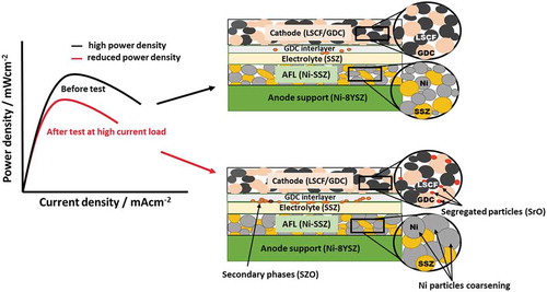
The use of high current density in anode-supported FT-SOFCs can cause local Joule heating at the active area, which can resultantly increase the degradation behavior of cells and stacks [Citation48,Citation51,Citation107,Citation162]. Besides, the mechanical stability of anode/electrolyte is directly affected by the steam produced due to the high operating current in anode-supported FT-SOFCs [Citation163,Citation164]. The applied current density affects the long-term performance degradation behavior of FT-SOFCs, and various studies have reported the degradation mechanisms of anode-supported FT-SOFCs due to applied current density. Among them, Khan et al. [Citation92] conducted the long-term performance degradation tests of anode-supported FT-SOFC at current densities of 200, 450, 700, and 1000 mAcm−2 for 1000 h, at 800°C. The results revealed that the voltage decreased with an increasing current density as shown in . As it can be observed in , that the rapid decrease in voltage occurs in the 200–400 h operating time and, followed by a constant rate which shows a similar degradation mechanism in all cells. The decrease in voltage was 30 mV after the 1000 h long-term degradation test for the cell operated at 200 mAcm-2 whereas it increased to 190 mV for the cell tested at 1000 mAcm-2. Moreover, the cell tested at 1000 mAcm-2 showed the highest decrease of 231 mWcm−2 in the peak power density after 1000 h operation, while the cell tested at 200 mAcm−2 exhibited the lowest decline of 58 mWcm−2 in the peak power density. The impedance results showed that the ohmic resistance and electrodes polarization increased by increasing the applied current density. One of the degradation mechanisms at higher current densities was recognized to be the coarsening of Ni particles in anode due to high steam content with increasing applied current density as shown in -). The higher steam content enhanced the mass transfer resistance in the anode support. Also, the migration of Sr from the cathode toward the GDC interlayer and electrolyte at high current densities resulted in the formation of an insulating phase, such as SZO, which eventually degraded the electrochemical performance of the SOFC. The quantity of the SZO phase formation was observed to increase with the raise in applied current density as displayed in -). Moreover, the presence of small particles in CFL also contributed to the decay of the long-term performance of anode-supported FT-SOFC. The observed smaller particles in the cells after operation at high current load, refer to the Sr surface segregated particles such as SrO which are insulating in nature. These particles cover the active electrochemical surface area of the cathode and increase the cathode polarization resistance [Citation165–167]. These observed degradation mechanisms are graphically summarized in . Furthermore, Khan et al. [Citation23] extensively investigated the coarsening effect of Ni particles in FT-SOFC anode using experimental and mathematical approaches at a high temperature of 900°C. The change in TPB length and particle size due to Ni coarsening in anode was predicted mathematically and co-related well to the experimental results. Based on the time-dependent Ni coarsening results, it is suggested that surface diffusion along the interface is the dominant Ni particle coarsening phenomenon. The calculated TPB length volume (Lv(TPB)) using the power-law coarsening model was found to be consistent with the experimental data. The predicted and experimental results showed that Lv(TPB) decreased with increasing time due to Ni agglomeration. Moreover, the measured time-dependent charge-transfer resistance of anode also co-related well with the calculated data from Lv(TPB). Similarly, this Ni coarsening degradation phenomenon is widely studied for the SOFC anodes in the literature [Citation168–172]. On the other hand, Kim et al. [Citation117] studied the degradation behavior of various cathode current-collecting materials for anode-supported FT-SOFC. Several conductive pastes such as Ag-Pd, Pt, La0.6Sr0.4COO3 (LSCO), and LSCF were painted between the cathode and Ag current collecting wire. The cathode with LSCo current collecting paste on Ag wire showed the least degradation rate and highest long-term performance stability. On the other hand, Pt paste coated cell performed well initially, however, degraded at a higher rate due to rising polarization resistance after 925 h. Moreover, the LSCF paste cell had higher ohmic resistance than the LSCO paste cell, which resulted in poor performance. The metal particle sintering in the Ag-Pd paste cell resulted in the formation of a dense paste layer at 750°C, which led to the poorest long-term stability and performance by this cell. Guan et al. [Citation173] investigated the degradation mechanism of anode-supported FT-SOFCs using symmetric cells with double-sided LSCF-GDC cathodes. The degradation was studied under 102 thermal cycles and the results indicated that power degradation took place for the initial 100 cycles between 750–200°C. Subsequently, for the 101st and 102nd thermal cycles, the cathode side was loaded with a force that led to better power output than the initial power. Besides, the ohmic impedance was also observed to have decreased due to the applied force. This behavior showed that the degradation for the initial 100 cycles was due to delamination between the cathode and the interlayer, which primarily took place during the early 34 cycles and the degradation for this cell can be avoided by using a moderate force on the cathode side. Yoshikawa et al. [Citation161] explored six different types of SOFCs including FT stack and discussed their durability and prominent factors contributing to the degradation. The degradation in the FT-SOFC stack was due to contamination of the cathode by sulfur which caused overvoltage at the cathode and IR drop. A chemical filter for SO2 was used to prevent the contamination of the cathode from the sulfur. Pi et al. [Citation149] analyzed the performance and durability of anode-supported FT-SOFCs, with Ag-infiltered cathodes. The electrochemical results revealed that the infiltration of Ag in the cathode enhanced the performance of the cell. The power density also increased and the maximum value of 537 mWcm−2 at 18 wt% Ag infiltration was achieved. The durability tests showed that further infiltration of Ag in cathode degraded the cell performance over time due to the agglomeration of Ag particles. A mitigation technique of co-infiltration of Ag and CeO2 in the cathode maintained the performance of cells at moderate temperatures by inhibiting the agglomeration of Ag particles.
Figure 12. Voltage variation with time as a function of applied current density (Reproduced with permission from [Citation92])
![Figure 12. Voltage variation with time as a function of applied current density (Reproduced with permission from [Citation92])](/cms/asset/1fc9adab-ff40-46fd-bde7-d668721d5784/tace_a_1920135_f0012_b.gif)
Figure 13. BSE microstructure image of the Ni-SSZ AFL of (a) before cell test, after test for 1000 h at 800°C and (b) 200 mAcm−2 (c) 450 mAcm−2 (d) 700 mAcm−2 (e) 1000 mAcm−2, (Reproduced with permission from [Citation92])
![Figure 13. BSE microstructure image of the Ni-SSZ AFL of (a) before cell test, after test for 1000 h at 800°C and (b) 200 mAcm−2 (c) 450 mAcm−2 (d) 700 mAcm−2 (e) 1000 mAcm−2, (Reproduced with permission from [Citation92])](/cms/asset/d99588f4-39fd-44f9-aa05-f55be95e8cf3/tace_a_1920135_f0013_b.gif)
Figure 14. BSE microstructure image of the anode-supported SOFC and WDS elemental maps of Sr of (a) cell before test, after test for 1000 h at 800°C and (b) 200 mAcm−2 (c) 450 mAcm−2 (d) 700 mAcm−2 (e) 1000 mAcm−2, (Reproduced with permission from [Citation92])
![Figure 14. BSE microstructure image of the anode-supported SOFC and WDS elemental maps of Sr of (a) cell before test, after test for 1000 h at 800°C and (b) 200 mAcm−2 (c) 450 mAcm−2 (d) 700 mAcm−2 (e) 1000 mAcm−2, (Reproduced with permission from [Citation92])](/cms/asset/3027945a-d7e3-41f4-b584-2417087f2591/tace_a_1920135_f0014_oc.jpg)
Figure 15. Schematic representation of the anode-supported FT-SOFC degradation mechanisms after long-term degradation testing at high current load
6. Summary
High power density owing to the shorter current path, easy gas-tight sealing, resistance to thermal shock, and ease of fabrication have been recognized as the major distinguishing factors of the FT-SOFC cells and stacks from a design point of view. Scaling up the FT-SOFC technology was discussed and new stack designs are summarized. The maximum reported power density of the FT-SOFC in the literature was 830 and 796 mWcm−2 at 1000 and 800°C, respectively, however, the balance of plant must be considered for the industrial applications. The fabrication of the nanostructures using the infiltration process is found to be an effective process in the performance enhancement of the FT-SOFCs. However, the long-term operation at an intermediate temperature and relatively low applied current density results in longer stability of the cells and stacks. The focus of recent development in the anode-supported SOFC stack is the elimination of the metal interconnect plate to avoid cathode degradation by chromium poisoning. The FT-SOFCs offer an active research area with the objective of design optimization, better interconnect material development, and scaling up to the high-power output stacks.
Acknowledgments
The authors are thankful to Dr. Jong-Won Lee, Dr. Seung-Bok Lee and Dr. Tak-Hyoung Lim for their valuable suggestions in this work. This research did not receive any specific grant from funding agencies in the public, commercial, or not-for-profit sectors.
Disclosure statement
No potential conflict of interest was reported by the author(s).
References
- Ebbesen SD, Knibbe R, Mogensen M. Co-electrolysis of steam and carbon dioxide in solid oxide cells. J Electrochem Soc. 2012;159(8):F482–F489.
- Zheng Y, Wang J, Yu B, et al. A review of high temperature co-electrolysis of H 2 O and CO2 to produce sustainable fuels using solid oxide electrolysis cells (SOECs): advanced materials and technology. Chem Soc Rev. 2017;46:1427–1463.
- Stambouli AB, Traversa E. Solid oxide fuel cells (SOFCs): a review of an environmentally clean and efficient source of energy. Renewable Sustainable Energy Rev. 2002;6(5):433–455.
- Lee TS, Chung JN, Chen Y-C. Design and optimization of a combined fuel reforming and solid oxide fuel cell system with anode off-gas recycling. Energy Convers Manag. 2011;52(10):3214–3226.
- Jiang SP. Nanoscale and nano-structured electrodes of solid oxide fuel cells by infiltration: advances and challenges. Int J Hydrogen Energy. 2012;37(1):449–470.
- Singhal SC. Solid oxide fuel cells for stationary, mobile, and military applications. Solid State Ion. 2002;152–153:405–410.
- Da Silva FS, De Souza TM. Novel materials for solid oxide fuel cell technologies: a literature review. Int J Hydrogen Energy. 2017;42(41):26020–26036.
- Wachsman ED, Lee KT. Lowering the temperature of solid oxide fuel cells. Science. 2011;334(6058):935–939.
- Huijsmans JP, Van Berkel FP, Christie G. Intermediate temperature SOFC – a promise for the 21st century. J Power Sources. 1998;71(1–2):107–110.
- Ralph JM, Rossignol C, Kumar R. Cathode materials for reduced-temperature SOFCs. J Electrochem Soc. 2003;150(11):A1518.
- Yang C, Ren C, Yu L, et al. High performance intermediate temperature micro-tubular SOFCs with Ba0.9Co0.7Fe0.2Nb0.1O3−δ as cathode. Int J Hydrogen Energy. 2013;38(35):15348–15353.
- Papadam T, Goula G, Yentekakis IV. Long-term operation stability tests of intermediate and high temperature Ni-based anodes‘ SOFCs directly fueled with simulated biogas mixtures. Int J Hydrogen Energy. 2012;37(21):16680–16685.
- Qiu P, Yang X, Zhu T, et al. Review on core-shell structured cathode for intermediate temperature solid oxide fuel cells. Int J Hydrogen Energy. 2020;45(43):23160–23173.
- Ormerod RM. Solid oxide fuel cells. Chem Soc Rev. 2003;32(1):17–28.
- Gao Z, Mogni LV, Miller EC, et al. A perspective on low-temperature solid oxide fuel cells. Energy Environ Sci. 2016;9:1602–1644.
- Fergus JW. Metallic interconnects for solid oxide fuel cells. Mater Sci Eng. A. 2005;397(1–2):271–823.
- Huang K, Singhal SC. Cathode-supported tubular solid oxide fuel cell technology: a critical review. J Power Sources. 2013;237:84–97.
- Mahato N, Banerjee A, Gupta A, et al. Progress in material selection for solid oxide fuel cell technology: a review. Prog Mater Sci. 2015;72:141–337.
- Virkar A. The role of electrode microstructure on activation and concentration polarizations in solid oxide fuel cells. Solid State Ion. 2000;131(1–2):189–198.
- Ramı́rez-Cabrera E, Atkinson A, Chadwick D. Catalytic steam reforming of methane over Ce0.9Gd0.1O2−x. Appl Catal B Environ. 2004;47(2):127–131.
- Park S-Y, Na CW, Ahn JH, et al. Preparation of highly porous NiO–gadolinium-doped ceria nano-composite powders by one-pot glycine nitrate process for anode-supported tubular solid oxide fuel cells. J Asian Ceram Soc. 2014;2(4):339–346.
- Khan MS, Lee S-B, Song R-H, et al. Fundamental mechanisms involved in the degradation of nickel–yttria stabilized zirconia (Ni–YSZ) anode during solid oxide fuel cells operation: a review. Ceram Int. 2016;42(1):35–48.
- Khan MZ, Mehran MT, Song R-H, et al. A simplified approach to predict performance degradation of a solid oxide fuel cell anode. J Power Sources. 2018;391:94–105.
- Zhu J, Lin Z. Degradations of the electrochemical performance of solid oxide fuel cell induced by material microstructure evolutions. Appl Energy. 2018;231:22–28.
- Pihlatie MH, Kaiser A, Mogensen M, et al. Electrical conductivity of Ni-YSZ composites: degradation due to Ni particle growth. Solid State Ion. 2011;189(1):82–90.
- Klemenso T, Chung C, Larsen PH, et al. The mechanism behind redox instability of anodes in high-temperature SOFCs. J Electrochem Soc. 2005;152(11):A2186.
- Malzbender J, Wessel E, Steinbrech R. Reduction and re-oxidation of anodes for solid oxide fuel cells. Solid State Ion. 2005;176(29–30):2201–2203.
- Klemensø T, Mogensen M. Ni–YSZ solid oxide fuel cell anode behavior upon redox cycling based on electrical characterization. J Am Ceram Soc. 2007;90(11):3582–3588.
- Bartholomew CH. Mechanisms of catalyst deactivation. Appl Catal A Gen. 2001;212(1–2):217–260.
- Wang W, Zhu C, Xie K, et al. High performance, coking-resistant and sulfur-tolerant anode for solid oxide fuel cell. J Power Sources. 2018;406:1–6.
- Seyednezhad M, Rajabi A, Muchtar A, et al. Effect of compaction pressure on the performance of a non-symmetrical NiO–SDC/SDC composite anode fabricated by conventional furnace. J Asian Ceram Soc. 2017;5(2):77–81.
- Kao C-T, Tuan W-H, Chang S-W. Thickness variations in electrolytes for planar solid oxide fuel cells. J Asian Ceram Soc. 2019;7(1):31–35.
- Miao H, Liu G, Zhang Y, et al. Improving the electrochemical properties of SSZ electrolyte-supported solid oxide fuel cells. Ceram Int. 2014;40(9):14621–14626.
- Kobayashi K. Supported Zr(Sc)O2 SOFCs for reduced temperature prepared by electrophoretic deposition. Solid State Ion. 2002;152–153:591–596.
- Zhao W, An S, Ma L. Processing and characterization of Bi2O3 and Sm2O3 Codoped CeO2 electrolyte for intermediate-temperature solid oxide fuel cell. J Am Ceram Soc. 2011;94(5):1496–1502.
- Lin SE, Wei WCJ. Long-term degradation of Ta2O5-doped Bi2O3 systems. J Eur Ceram Soc. 2011;31(16):3081–3086.
- Laurent K, Wang G, Tusseaunenez S, et al. Structure and conductivity studies of electrodeposited δ-Bi2O3. Solid State Ion. 2008;178(33–34):1735–1739.
- Singhal SC, Kendall K. High-temperature solid oxide fuel cells: fundamentals, design, and applicatons. Oxford: Elsevier; 2003.
- Ma X, Dai J, Zhang H, et al. Solid oxide fuel cell development by using novel plasma spray techniques. J Fuel Cell Sci Technol. 2005;2(3):190–196.
- Ma XQ, Zhang H, Dai J, et al. Intermediate temperature solid oxide fuel cell based on fully integrated plasma-sprayed components. J Therm Spray Technol. 2005;14(1):61–66.
- Adler SB. Factors governing oxygen reduction in solid oxide fuel cell cathodes †. Chem Rev. 2004;104(10):4791–4844.
- Jiang SP. Development of lanthanum strontium manganite perovskite cathode materials of solid oxide fuel cells: a review. J Mater Sci. 2008;43(21):6799–6833.
- Tsai T. Effect of LSM-YSZ cathode on thin-electrolyte solid oxide fuel cell performance. Solid State Ion. 1997;93(3–4):207–217.
- Sun C, Hui R, Roller J. Cathode materials for solid oxide fuel cells: a review. J Solid State Electrochem. 2010;14(7):1125–1144.
- Li Y, Zhang W, Zheng Y, et al. Controlling cation segregation in perovskite-based electrodes for high electro-catalytic activity and durability. Chem Soc Rev. 2017;46(20):6345–6378.
- Chen T, Liu M, Yuan C, et al. High performance of intermediate temperature solid oxide electrolysis cells using Nd2NiO4+δ impregnated scandia stabilized zirconia oxygen electrode. J Power Sources. 2015;276:1–6.
- Montenegro-Hernández A, Vega-Castillo J, Mogni L, et al. Thermal stability of Ln2NiO4+δ (Ln: la, Pr, Nd) and their chemical compatibility with YSZ and CGO solid electrolytes. Int J Hydrogen Energy. 2011;36(24):15704–15714.
- Khan MZ, Song RH, Lee SB, et al. Effect of GDC interlayer on the degradation of solid oxide fuel cell cathode during accelerated current load cycling. Int J Hydrogen Energy. 2014;39:20799–20805.
- Khan MZ, Song R-H, Mehran MT, et al. Controlling cation migration and inter-diffusion across cathode/interlayer/electrolyte interfaces of solid oxide fuel cells: a review. Ceram Int. 2021;47:5839–5869.
- Kim S, Woo Joh D, Lee D-Y, et al. Microstructure tailoring of solid oxide electrolysis cell air electrode to boost performance and long-term durability. Chem Eng J. 2020;410:128318.
- Khan MZ, Mehran MT, Song RH, et al. Effects of applied current density and thermal cycling on the degradation of a solid oxide fuel cell cathode. Int J Hydrogen Energy. 2018;43(27):12346–12357.
- Kim SJ, Kim SW, Park YM, et al. Effect of Gd-doped ceria interlayer on the stability of solid oxide electrolysis cell. Solid State Ion. 2016;295:25–31.
- Chen Y, Téllez H, Burriel M, et al. Segregated chemistry and structure on (001) and (100) Surfaces of (La1–x Srx)2CoO4 override the crystal anisotropy in oxygen exchange kinetics. Chem Mater. 2015;27(15):5436–5450.
- Ponce S, Peña M, Fierro JL. Surface properties and catalytic performance in methane combustion of Sr-substituted lanthanum manganites. Appl Catal B Environ. 2000;24(3–4):193–205.
- Liu J. Operation of anode-supported solid oxide fuel cells on methane and natural gas. Solid State Ion. 2003;158(1–2):11–16.
- Leng Y. Performance evaluation of anode-supported solid oxide fuel cells with thin film YSZ electrolyte. Int J Hydrogen Energy. 2004;29(10):1025–1033.
- Zhang S, Bi L, Zhang L, et al. Fabrication of cathode supported solid oxide fuel cell by multi-layer tape casting and co-firing method. Int J Hydrogen Energy. 2009;34(18):7789–7794.
- Kim SJ, Choi MB, Park M, et al. Acceleration tests: degradation of anode-supported planar solid oxide fuel cells at elevated operating temperatures. J Power Sources. 2017;360:284–293.
- Hussain A, Khan MZ, Song RH, et al. High performing and durable anode-supported solid oxide fuel cell by using tape casting, lamination and co-firing method. ECS Trans. 2019;91(1):373–379.
- Jiang Y, Virkar AV. A high performance, anode-supported solid oxide fuel cell operating on direct alcohol. J Electrochem Soc. 2001;148(7):A706.
- Accardo G, Kim GS, Ham HC, et al. Optimized lithium-doped ceramic electrolytes and their use in fabrication of an electrolyte-supported solid oxide fuel cell. Int J Hydrogen Energy. 2019;44(23):12138–12150.
- Muccillo R, Muccillo ENS, Fonseca FC, et al. Characteristics and performance of electrolyte-supported solid oxide fuel cells under ethanol and hydrogen. J Electrochem Soc. 2008;155(3):B232.
- Tiwari P, Basu S. Performance studies of electrolyte-supported solid oxide fuel cell with Ni–YSZ and Ni–TiO2–YSZ as anodes. J Solid State Electrochem. 2014;18(3):805–812.
- Singhal SC Progress in tubular solid oxide fuel cell technology. Proceeding of the Solid Oxide Fuel Cells Conference; 1999. p. 39–51. Honolulu, Hawaii.
- Mahmud LS, Muchtar A, Somalu MR. Challenges in fabricating planar solid oxide fuel cells: a review. Renewable Sustainable Energy Rev. 2017;72:105–116.
- Li P, Yu B, Li J, et al. A single layer solid oxide fuel cell composed of La2NiO4 and doped ceria-carbonate with H2 and methanol as fuels. Int J Hydrogen Energy. 2016;41(21):9059–9065.
- Lee D, Kim J, Moon J. Co-planar single chamber solid oxide fuel cells with concentric electrodes. J Asian Ceram Soc. 2014;2(3):185–189.
- Du Y, Sammes NM. Fabrication and properties of anode-supported tubular solid oxide fuel cells. J Power Sources. 2004;136(1):66–71.
- Howe KS, Thompson GJ, Kendall K. Micro-tubular solid oxide fuel cells and stacks. J Power Sources. 2011;196(4):1677–1686.
- Lin C-K, Huang L-H, Chiang L-K, et al. Thermal stress analysis of planar solid oxide fuel cell stacks: effects of sealing design. J Power Sources. 2009;192(2):515–524.
- Sohn S-B, Choi S-Y, Kim G-H, et al. Stable sealing glass for planar solid oxide fuel cell. J Non Cryst Solids. 2002;297(2–3):103–112.
- Lu L, Liu W, Wang J, et al. Long-term stability of carbon dioxide electrolysis in a large-scale flat-tube solid oxide electrolysis cell based on double-sided air electrodes. Appl Energy. 2020;259:114130.
- Park S, Sammes NM, Song KH, et al. Monolithic flat tubular types of solid oxide fuel cells with integrated electrode and gas channels. Int J Hydrogen Energy. 2017;42(2):1154–1160.
- Kim JH, Song RH, Song KS, et al. Fabrication and characteristics of anode-supported flat-tube solid oxide fuel cell. J Power Sources. 2003;122(2):138–143.
- Lu Y, Schaefer L. Numerical study of a flat-tube high power density solid oxide fuel cell. J Power Sources. 2006;153(1):68–75.
- Kim S-D, Yu J-H, Seo D-W, et al. Hydrogen production performance of 3-cell flat-tubular solid oxide electrolysis stack. Int J Hydrogen Energy. 2012;37(1):78–83.
- Hassmann K. SOFC power plants, the Siemens-Westinghouse approach. Fuel Cells. 2001;1(1):78–84.
- Singhal SC, Sg. Processing and characterization of electrochemical materials and devices. Westerville, OH: The American Ceramic Society, Inc.; 1999.
- Mehran MT, Khan MZ, Lim T-H, et al. Effect of nano-Al2O3 addition on mechanical durability of nickel-yttria stabilized zirconia anode support of solid oxide fuel cells. Ceram Int. 2018;44(12):14824–14833.
- Iyengar AKS, Desai NA, Vora SD, et al. Numerical investigation of a delta high power density cell and comparison with a flattened tubular high power density cell. J Fuel Cell Sci Technol. 2010;7(6). DOI:https://doi.org/10.1115/1.4000996.
- Park J, Bae J, Kim J-Y. A numerical study on anode thickness and channel diameter of anode-supported flat-tube solid oxide fuel cells. Renew Energy. 2012;42:180–185.
- Mushtaq U, Kim DW, Yun UJ, et al. Effect of cathode geometry on the electrochemical performance of flat tubular segmented-inseries(SIS) solid oxide fuel cell. Int J Hydrogen Energy. 2015;40(18):6207–6215.
- Park BK, Kim DW, Song RH, et al. Design of a dual-layer ceramic interconnect based on perovskite oxides for segmented-in-series solid oxide fuel cells. J Power Sources. 2015;300:318–324.
- Vora S. 10th SECA Workshop; 2009, Pittsburgh, USA.
- Vora S. 9th SECA Workshop; 2008, Pittsburgh, USA.
- Sammes NM, Du Y, Bove R. Design and fabrication of a 100 W anode supported micro-tubular SOFC stack. J Power Sources. 2005;145(2):428–434.
- Lawlor V. Review of the micro-tubular solid oxide fuel cell (Part II: cell design issues and research activities). J Power Sources. 2013;240:421–441.
- Shri Prakash B, Senthil Kumar S, Aruna ST. Properties and development of Ni/YSZ as an anode material in solid oxide fuel cell: a review. Renewable Sustainable Energy Rev. 2014;36:149–179.
- Park BK, Lee JW, Lee SB, et al. La-doped SrTiO3 interconnect materials for anode-supported flat-tubular solid oxide fuel cells. Int J Hydrogen Energy. 2012;37:4319–4323.
- Raeis Hosseini N, Sammes NM, Chung JS. Manganese-doped lanthanum calcium titanate as an interconnect for flat-tubular solid oxide fuel cells. J Power Sources. 2014;245:599–608.
- Park BK, Lee JW, Lee SB, et al. A flat-tubular solid oxide fuel cell with a dense interconnect film coated on the porous anode support. J Power Sources. 2012;213:218–222.
- Khan MZ, Song RH, Hussain A, et al. Effect of applied current density on the degradation behavior of anode-supported flat-tubular solid oxide fuel cells. J Eur Ceram Soc. 2020;40(4):1407–1417.
- An YT, Ji MJ, Hwang HJ, et al. Fabrication of a flat tubular segmented-in-series solid oxide fuel cell using decalcomania paper. Fuel Cells. 2015;15(4):566–570.
- Timurkutluk B, Timurkutluk C, Mat MD, et al. A review on cell/stack designs for high performance solid oxide fuel cells. Renewable Sustainable Energy Rev. 2016;56:1101–1121.
- Orui H, Watanabe K, Arakawa M. Electrochemical characteristics of tubular flat-plate-SOFCs fabricated by co-firing cathode substrate and electrolyte. J Power Sources. 2002;112(1):90–97.
- Itoh H, Yamamoto T, Mori M, et al. Configurational and electrical behavior of Ni‐YSZ cermet with novel microstructure for solid oxide fuel cell anodes. J Electrochem Soc. 2019;144:641.
- Jiang SP, Badwal SPS. An electrode kinetics study of H2 oxidation on Ni/Y2O3a “ZrO2 cermet electrode of the solid oxide fuel cell. Solid State Ion. 1999;123(1–4):209–224.
- Hassan AAE, Menzler NH, Blass G, et al. Development of an optimized anode functional layer for solid oxide fuel cell applications. Adv Eng Mater. 2002;4(3):125.
- De Boer B, Gonzalez M, Bouwmeester HJM, et al. Effect of the presence of fine YSZ particles on the performance of porous nickel electrodes. Solid State Ion. 2000;127(3–4):269–276.
- Yang YZ, Zhang HO, Wang GL, et al. Fabrication of functionally graded SOFC by APS. J Therm Spray Technol. 2007;16(5–6):768–775.
- Wang Z, Zhang N, Qiao J, et al. Improved SOFC performance with continuously graded anode functional layer. Electrochem Commun. 2009;11(6):1120–1123.
- Lim TH, Park JL, Lee SB, et al. Fabrication and operation of a 1 kW class anode-supported flat tubular SOFC stack. Int J Hydrogen Energy. 2010;35(18):9687–9692.
- Somalu MR, Brandon NP. Rheological studies of nickel/scandia-stabilized-zirconia screen printing inks for solid oxide fuel cell anode fabrication. J Am Ceram Soc. 2012;95:1220–1228.
- Somalu MR, Yufit V, Brandon NP. The effect of solids loading on the screen-printing and properties of nickel/scandia-stabilized-zirconia anodes for solid oxide fuel cells. Int J Hydrogen Energy. 2013;38(22):9500–9510.
- Yoon D, Lee -J-J, Park H-G, et al. NiO/YSZ–YSZ nanocomposite functional layer for high performance solid oxide fuel cell anodes. J Electrochem Soc. 2010;157:B455.
- Torabi A, Etsell TH, Sarkar P. Dip coating fabrication process for micro-tubular SOFCs. Solid State Ion. 2011;192(1):372–375.
- Khan MZ, Song R-H, Lee S-B, et al. Lifetime prediction of anode-supported solid oxide fuel cell on the basis of individual components degradation. ECS Trans. 2019;91(1):621–627.
- Simon L, Le Dren S, Gonnard P. PZT and PT screen-printed thick films. J Eur Ceram Soc. 2001;21:1441–1444.
- Chu WF. Thin- and thick-film solid ionic devices. Solid State Ion. 1992;52(1–3):243–248.
- An YT, Ji MJ, Seol KH, et al. Characteristics of flat-tubular ceramic supported segmented-in-series solid oxide fuel cell on all sides laminating using decalcomania method. J Power Sources. 2014;262:323–327.
- Cho HR, Choi BH, An YT, et al. Effect of an anode functional layer on cell performance of anode-supported solid oxide fuel cells by a decalcomania method. J Korean Inst Met Mater. 2013;51(2):125–130.
- An YT, Ji MJ, Bin GJ, et al. Power densities according to anode functional layers on the manufactured SOFC unit cells using decalcomania method. Korean J Mater Res. 2012;22(11):626–630.
- Xu X, Xia C, Huang S, et al. YSZ thin films deposited by spin-coating for IT-SOFCs. Ceram Int. 2005;31:1061–1064.
- Son HJ, Song RH, Lim TH, et al. Effect of fabrication parameters on coating properties of tubular solid oxide fuel cell electrolyte prepared by vacuum slurry coating. J Power Sources. 2010;195(7):1779–1785.
- Jordan N, Assenmacher W, Uhlenbruck S, et al. Ce0.8Gd0.2O2-δ protecting layers manufactured by physical vapor deposition for IT-SOFC. Solid State Ion. 2008;179(21–26):919–923.
- Ballard JD, Davenport J, Lewis C, et al. Phase stability of thermal barrier coatings made from 8 wt.% Yttria stabilized Zirconia: a technical note. J Therm Spray Technol. 2003;12(1):34–37.
- Kim JH, Song RH, Chung DY, et al. Degradation of cathode current-collecting materials for anode-supported flat-tube solid oxide fuel cell. J Power Sources. 2009;188(2):447–452.
- Kingery WD, Bowen HK, Uhlmann DR. Introduction to Ceramics. Canada: John Wiley & Sons, Inc.; 1976.
- Lee S-B, Lee J-W, Lim T-H, et al. Development of anode-supported flat-tube solid oxide fuel cell (SOFC) stack with high power density. ECS Trans. 2019;35(1):327.
- Lee MJ, Kim BN, Lim TY, et al. The properties of the manufactured SOFC unit cell using decalcomania method. J Korean Ceram Soc. 2011;48(6):520–524.
- An YT, Ji MJ, Park SM, et al. Fabrication and cell properties of flattened tube segmented-in-series solid oxide fuel cell-stack using decalcomania paper. Korean J Mater Res. 2013;23(3):206–210.
- Pal UB, Singhal SC. Growth of perovskite films by electrochemical vapor deposition. High Temp Sci. 1988;27:251–264.
- Pal UB, Singhal SC. Electrochemical vapor deposition of Yttria‐stabilized Zirconia films. J Electrochem Soc. 2019;137:2937.
- Suzuki T, Liang B, Yamaguchi T, et al. Development of novel micro flat-tube solid-oxide fuel cells. Electrochem Commun. 2011;13(7):719–722.
- Kim DW, Yun UJ, Lee JW, et al. Fabrication and operating characteristics of a flat tubular segmented-in-series solid oxide fuel cell unit bundle. Energy. 2014;72:215–221.
- Pan J, Fan Z, Yan D, et al. The investigation of in-situ protection effect of LaCo0.6Ni0.4O3-δ cathode contact layer on high temperature oxidation of Fe-16Cr alloy as solid oxide fuel cell interconnect. J Alloys Compd. 2020;832:154904.
- Li Y, Wu J, Johnson C, et al. Oxidation behavior of metallic interconnects for SOFC in coal syngas. Int J Hydrogen Energy. 2009;34:1489–1496.
- Mehran MT, Song R-H, Lee J-W, et al. Nano-oxide dispersed ferritic stainless steel for metallic interconnects of solid oxide fuel cells. ECS Trans. 2017;78(1):1575–1582.
- Laosiripojana N, Wiyaratn W, Kiatkittipong W, et al. Reviews on solid oxide fuel cell technology. Eng J. 2009;13(1):65–83.
- Saleem M, Kim I, Kim M-S, et al. Electromechanical properties of Nb doped 0.76Bi 0.5 Na0.5TiO3 –0.24SrTiO3 ceramic. RSC Adv. 2016;6(92):89210–89220.
- Kim T-H, Khan MZ, Song R-H, et al. Development of oxide dispersed ferritic steel as a solid oxide fuel cell interconnect. ECS Trans. 2019;91:2307–2312.
- Xu Y, Wang S, Liu R, et al. A novel bilayered Sr0.6La0.4TiO3/La0.8Sr0.2MnO3 interconnector for anode-supported tubular solid oxide fuel cell via slurry-brushing and co-sintering process. J Power Sources. 2011;196:1338–1341.
- Pi SH, Lee SB, Song RH, et al. Novel Ag-glass composite interconnect materials for anode-supported flat-tubular solid oxide fuel cells operated at an intermediate temperature. Fuel Cells. 2013;13(3):392–397.
- Yoon H, Kim T, Park S, et al. Stable LSM/LSTM bi-layer interconnect for flat-tubular solid oxide fuel cells. Int J Hydrogen Energy. 2018;43(1):363–372.
- Chung D-Y, Heo Y-H, Lee S-B, et al. Induction brazing for gas sealing of anode-supported tubular solid oxide fuel cells using the nickel based brazing alloy modified by TiH2. Int J Hydrogen Energy. 2011;36(2):1890–1896.
- Lee S-B, Lee J-W, Lim T-H, et al. Development of anode-supported flat-tube Solid oxide fuel cell (SOFC) stack with high power density. ECS Trans. 2011;35:327–332.
- Ji W, Zhang L, Ming L, et al. Design and fabrication of a 600W anode supported flat tubular SOFC stack. ECS Trans. 2015;68:1865–1869.
- Collie JC Connections for solid oxide fuel cells. United States patent US 6,001,501, 1999.
- Song RH, Shin DRKJ Anode-supported flat-tubular solid oxide fuel cell stack and fabrication method of the same. United States patent US 7,285,347 B2, 2007.
- Wei B, Chen K, Zhao L, et al. Chromium deposition and poisoning at La0.6Sr0.4Co0.2Fe0.8 O3−δ oxygen electrodes of solid oxide electrolysis cells. Phys Chem Chem Phys. 2015;17(3):1601–1609.
- Yokokawa H, Horita T, Yamaji K, et al. Chromium poisoning of LaMnO3-based cathode within generalized approach. Fuel Cells. 2013;13(4):526–535.
- Konysheva E, Penkalla H, Wessel E, et al. Chromium poisoning of Perovskite cathodes by the ODS alloy Cr5Fe1Y2O3 and the high chromium ferritic steel Crofer22APU. J Electrochem Soc. 2006;153(4):A765.
- Paulson SC, Birss VI. Chromium poisoning of LSM-YSZ SOFC cathodes. J Electrochem Soc. 2004;151(11):A1961.
- Mehran MT, Kim TH, Khan MZ, et al. Highly durable nano-oxide dispersed ferritic stainless steel interconnects for intermediate temperature solid oxide fuel cells. J Power Sources. 2019;439:227109.
- Hwang HJ, Moon J-W, Lee S, et al. Electrochemical performance of LSCF-based composite cathodes for intermediate temperature SOFCs. J Power Sources. 2005;145(2):243–248.
- Tu B, Yin Y, Zhang F, et al. High performance of direct methane-fuelled solid oxide fuel cell with samarium modified nickel-based anode. Int J Hydrogen Energy. 2020;45(51):27587–27596.
- Cui D, Ji Y, Chang C, et al. Influence of fuel flow rate on the performance of micro tubular solid oxide fuel cell. Int J Hydrogen Energy. 2020;45(24):13459–13468.
- Onbilgin S, Timurkutluk B, Timurkutluk C, et al. Comparison of electrolyte fabrication techniques on the performance of anode supported solid oxide fuel cells. Int J Hydrogen Energy. 2020;45:35162–35170.
- Pi SH, Lee JW, Lee SB, et al. Performance and durability of anode-supported flat-tubular solid oxide fuel cells with Ag-infiltrated cathodes. J Nanosci Nanotechnol. 2014;14(10):7668–7673.
- Liu Z, Liu B, Ding D, et al. Fabrication and modification of solid oxide fuel cell anodes via wet impregnation/infiltration technique. J Power Sources. 2013;237:243–259.
- Dowd RP, Lee S, Fan Y, et al. Engineering the solid oxide fuel cell electrocatalyst infiltration technique for industrial use. Int J Hydrogen Energy. 2016;41:14971–14981.
- Song Y-H, Rehman SU, Kim H-S, et al. Facile surface modification of LSCF/GDC cathodes by epitaxial deposition of Sm0.5Sr0.5CoO3 via ultrasonic spray infiltration. J Mater Chem A. 2020;8:3967–3977.
- Soydan AM, Yıldız Ö, Durğun A, et al. Production, performance and cost analysis of anode-supported NiO-YSZ micro-tubular SOFCs. Int J Hydrogen Energy. 2019;44(57):30339–30347.
- Mohamed MH, Othman MHD, Hubadillah SK, et al. Comparative study on the performance of co-extruded hollow fiber solid oxide fuel cell fuelled with hydrogen and methane. J Solid State Electrochem. 2019;23(7):2195–2203.
- Omar AF, Othman MHD, Gunaedi CN, et al. Performance analysis of hollow fibre-based micro-tubular solid oxide fuel cell utilising methane fuel. Int J Hydrogen Energy. 2019;44(58):30754–30762.
- Liu Y-X, Wang S-F, Hsu Y-F, et al. Characteristics of La0.8Sr0.2Ga0.8Mg0.2O3-δ-supported micro-tubular solid oxide fuel cells with LaCo0.4Ni0.6-xCuxO3-δ cathodes. Int J Hydrogen Energy. 2018;43(11):5703–5713.
- Han Z, Yang Z, Han M. Fabrication of metal-supported tubular solid oxide fuel cell by phase-inversion method and in situ reduction. Int J Hydrogen Energy. 2016;41:10935–10941.
- Ye XF, Yuan C, Chen YP, et al. Micro-tubular solid oxide fuel cells and their stacks running on direct ethanol fuels. J Electrochem Soc. 2014;161(9):F894–F898.
- Hsieh W-S, Lin P, Wang S-F. Fabrication of electrolyte supported micro-tubular SOFCs using extrusion and dip-coating. Int J Hydrogen Energy. 2013;38(6):2859–2867.
- Blum L, De Haart LGJ, Malzbender J, et al. Anode-supported solid oxide fuel cell achieves 70 000 hours of continuous operation. Energy Technol. 2016;4(8):939–942.
- Yoshikawa M, Yamamoto T, Yasumoto K, et al. Degradation analysis of SOFC stack performance-durability test and verification of improved SOFCs-. ECS Trans. 2017;75(42):23–31.
- Khan MZ, Mehran MT, Song R-H, et al. Effect of GDC interlayer thickness on durability of solid oxide fuel cell cathode. Ceram Int. 2016;42(6):6978–6984.
- Hagen A, Barfod R, Hendriksen PV, et al. Degradation of anode supported SOFCs as a function of temperature and current load. J Electrochem Soc. 2006;153(6):A1165.
- Torrell M, Morata A, Kayser P, et al. Performance and long term degradation of 7W micro-tubular solid oxide fuel cells for portable applications. J Power Sources. 2015;285:439–448.
- Yu Y, Ludwig KF, Woicik JC, et al. Effect of Sr content and strain on Sr surface segregation of La1-xSrxCo0.2Fe0.8O3-δ as cathode material for solid oxide fuel cells. ACS Appl Mater Interfaces. 2016;8(40):26704–26711.
- Ding H, Virkar AV, Liu M, et al. Suppression of Sr surface segregation in La1−xSrxCo1−y FeyO3−δ : a first principles study. Phys Chem Chem Phys. 2013;15:489–496.
- Giannici F, Canu G, Chiara A, et al. Cation diffusion and segregation at the interface between samarium-doped ceria and LSCF or LSFCu cathodes investigated with X-ray microspectroscopy. ACS Appl Mater Interfaces. 2017;9(51):44466–44477.
- Chen HY, Yu HC, Cronin S, et al. Simulation of coarsening in three-phase solid oxide fuel cell anodes. J Power Sources. 2011;196(3):1333–1337.
- Kennouche D, Chen-Wiegart YK, Riscoe C, et al. Combined electrochemical and X-ray tomography study of the high temperature evolution of Nickel – Yttria stabilized Zirconia solid oxide fuel cell anodes. J Power Sources. 2016;307:604–612.
- Kennouche D, Karen Chen-Wiegart Y, Scott Cronin J, et al. Three-dimensional microstructural evolution of Ni- Yttria-stabilized Zirconia solid oxide fuel cell anodes at elevated temperatures. J Electrochem Soc. 2013;160(11):1293–1304.
- Wilson JR, Kobsiriphat W, Mendoza R, et al. Three-dimensional reconstruction of a solid-oxide fuel-cell anode. Nat Mater. 2006;5(7):541–544.
- Mehran MT, Khan MZ, Lee S-B, et al. Improving sulfur tolerance of Ni-YSZ anodes of solid oxide fuel cells by optimization of microstructure and operating conditions. Int J Hydrogen Energy. 2018;43(24):11202–11213.
- Guan W, Du Z, Wang J, et al. Mechanisms of performance degradation induced by thermal cycling in solid oxide fuel cell stacks with flat-tube anode-supported cells based on double-sided cathodes. Int J Hydrogen Energy. 2020;45(38):19840–19846.