
ABSTRACT
The immobilization of fluorescent nanomaterials in host–guest systems is one of the important factors for the further development of light-emitting properties in nanocomposite materials. In this study, one-pot hydrothermal synthesis was performed to generate advanced fluorescent nanocomposite by immobilizing carbon dots (C-dots) in a layered hydrozincite matrix while synthesizing them in a reaction solution. The one-pot reaction was performed by hydrothermal treatment starting from zinc acetate, urea, and diammonium hydrogen citrate in solution as precursor. The reaction condition that C-dots and hydrozincite could be synthesized together in a one-pot hydrothermal reaction at 200°C was investigated by adjusting the pH of the precursor, and the formation criteria depending on the pH were discussed. Based on the changes in crystal structure and in the surface state of the resulting composite powder compared with the single hydrozincite powder, the interaction that contributed to the immobilization of carbon dots was discussed. The fluorescence properties of the C-dots immobilized zinc compounds were characterized. Further sintering under an appropriate condition for the C-dots–hydrozincite composite allowed conversion into the C-dots–zinc oxide composite exhibiting quite different fluorescent characteristics.
1. Introduction
In recent years, the development of host–guest systems in inorganic matrices containing carbon dots (C-dots), zero-dimensional carbogenic nanomaterials exhibiting unique fluorescence characteristics, has been widely carried out. Among them, the composite system using semiconductive ZnO together with C-dots is attracting attention as a low-cost and highly functional materials for catalysts [Citation1], electrodes [Citation2], solar cells [Citation3], photocurrent [Citation4], and emitting devices applications [Citation5]. In the C-dots–ZnO nanocomposite solid-state systems, dispersion, immobilization, and stabilization are important factors for the generation of the above physical properties [Citation6]. Unlike the organic matrices, such as polymers and resins, it is difficult for the inorganic matrices, such as metal oxide and glass, to work with strong chemical bonding with C-dots. In fact, in most cases of the previous studies, ZnO and C-dots were separately synthesized and combined later, making it difficult to cause an interaction in the compositing process [Citation1–5,Citation7,Citation8]. An acceptable design that promotes “on-site” chemical interaction between host–guest systems during these materials construction is required to immobilize the C-dots in the inorganic matrix stably.
In this study, hydrozincite, which has the potential structures to interact with C-dots as a host matrix and can be easily converted into zinc oxide by simple sintering, has been focused on [Citation9]. C-dots, the guest materials, are synthesized by a bottom-up approach in solution. When the starting materials of the small-molecule compounds are mixed in solution and thermally treated, they undergo polymerization, dehydration, carbonization, oxidation, and thermal decomposition, and form nano-sized dots with specific size, structure, and surface properties, which are the resulting C-dots. The reaction process is quite complicated, and the structural and physical characteristics of the resulting C-dots differ greatly even using the same starting materials depending on the synthetic parameters, such as starting materials ratio, thermal conditions, and reaction solvent [Citation10]. Hydrozincite, the host matrix, is one of the layered hydroxide salts containing carbonates between zinc layers and often takes in water molecules [Citation11]. Layered hydroxide salts are often applied to prepare nanocomposites with polymers utilizing the versatility of the pharmaceutical space, functional groups, or ion [Citation12]. One of the examples of the synthetic method of the layered hydrozincite, has been hydrothermal treatment, which uses zinc acetate and urea as starting materials [Citation13]. On the other hand, hydrothermal synthesis is widely used also for the production of C-dots with various surface functional groups, such as –NH2, –OH, –COOH, and –CONH, using urea and citrate as typical starting materials [Citation14–17]. Considering the combination of these two materials synthesized by a similar hydrothermal process, it is fully anticipated that the carbonate and the hydroxy groups of hydrozincite can interact with C-dots surface possessing various terminal functional groups. Therefore, a one-pot hydrothermal reaction for the synthesis of hydrozincite and C-dots in the same system has been attempted by mixing their starting materials that are commonly used for individual synthesis and combined synthesis. Nanocomposite formation of these materials taking into account their respective deposition conditions and their interactions is also considered in the one-pot hydrothermal reaction.
2. Experimental
2.1. One-pot hydrothermal synthesis of hydrozincite–carbon dots nanocomposite
All reagents were of analytical grade, supplied by FUJIFILM Wako Pure Chemical Corporation, JAPAN. As a precursor solution for hydrothermal synthesis, anhydrous zinc acetate (Zn(CH3COO)2 1 mmol), diammonium hydrogen citrate (DHC, C6H8O7‧2NH3, 0.5 mmol), and urea (NH2CONH2, 2 mmol) were mixed in 10 mL of distilled water. Sodium hydroxide (Granular) was then added under stirring to adjust the pH of 8.5 of the solution. For comparison, a suspension without adding the DHC (diammonium hydrogen citrate) was also prepared in the same manner. When the pH of the mixture exceeds around 7, the transparent mixture turns milky white gradually with pH increase for both precursors. The resulting milky white suspension was poured into a Teflon-lined autoclave for a hydrothermal treatment performed at 200°C keeping for 3 h, where the crucible-type autoclave was directly put in the oven at 200°C. After being heated for 3 h, the autoclave was cooled down naturally to room temperature. The obtained whitish powder with yellowish supernatant was washed several times by centrifugation in water and methanol to remove the supernatant and the unimmobilized carbon dots in hydrozincite matrix. The washed powder was dried at 70°C for 6 h in air for further characterization.
2.2. Characterization
The powder X-ray diffraction patterns of the samples were measured using an X-ray diffractometer with Cu Kα radiation (Rigaku Smart Lab III, Japan). The FT-IR spectra for the powder samples were measured using a spectrophotometer (Thermo Fisher Nicolet iS5, US) with ATR attachment (ATR iD5). The size and the morphology of the powder samples and the supernatant products were observed using a scanning electron microscope (SEM, Hitachi S-4500, Japan) and a transmission electron microscope (TEM, Thermo Fisher Talos F200X). The photoluminescence spectra including emission, excitation, and 3D map (excitation–emission–intensity) spectra were measured using a fluorescence spectrophotometer (SHIMADZU RF-6000, Japan). The powder samples were set by sandwiching them between non-fluorescent quartz substrates and measured. The photoluminescence quantum yield (PLQY) of the nanocomposite powders was measured in the same manner using an integrating sphere unit for RF-6000.
3. Results and discussion
3.1. Structures of carbon-dots-immobilized hydrozincite nanocomposite and the formation criteria
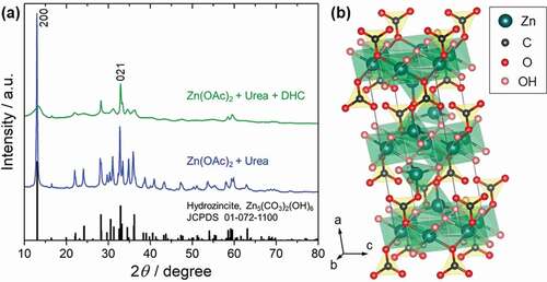
) shows the powder X-ray diffraction patterns of the samples obtained by hydrothermal synthesis. For the sample prepared without using citrate, the diffraction peaks are well assigned and indexed by hydrozincite C2/m, Zn5(CO3)2(OH)6, (JCPDS No. 01-072-1100) (shown as the blue line in )). In the sample prepared using citrate, a remarkable broadening of the peaks is observed. However, the peak position has mostly coincided with the hydrozincite (shown as the green line in )). In particular, the peak of the 200 plane at around 13.0º is broadened, indicating that the interlayer length between Zn atoms in the a-axis direction has a specific distribution ()). Meanwhile, the diffraction peak of the 021 plane at around 32.9º retains a relatively sharp shape, indicating that the crystallinity in the in-plane b-c axis direction is not so disturbed. From the difference in the XRD patterns, it is considered that in the powder sample prepared using the citrate, the layered structure of hydrozincite is disturbed due to an interaction with some substances derived from the citrate, or the substances are intercalated between the layers.
Figure 1. (a) XRD patterns of the obtained powders via hydrothermal synthesis indexed by hydrozincite, Zn5(CO3)2(OH)6 using different precursor; zinc acetate and urea precursor without using citrate source (blue line), and zinc acetate, urea and diammonium hydrogen citrate precursor (green line). (b) Crystallographic unit cell of hydrozincite, Zn5(CO3)2(OH)6 (JCPDS No. 01-072-1100)
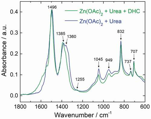
In order to understand the interaction of hydrozincite with the substances prepared in the zinc acetate–urea–diammonium hydrogen citrate system, the structural change using the citrate was investigated by FT-IR, as shown in . In the sample prepared without using citrate, the carbonate bands, which are the characteristics of hydrozincite, are well observed. The several bands at 1495, 1385, and 1360 cm−1 are ascribed to the ν3 (CO3)2– antisymmetric stretching modes in hydrozincite. The band at 832 cm−1 is assigned to the ν2 bending mode for carbonate. The bands are observed for the carbonate ν4 in phase bending modes at 737 and 707 cm−1 [Citation18]. The bands at 1045 and 949 cm−1 are assigned to the -OH bending mode [Citation19]. In the sample containing citrate as precursor, most of the bands are characterized with the hydrozincite, similar to the sample without using citrate. Meanwhile, the band corresponding to ν3 stretching modes around 1350 cm−1 is significantly reduced due to the symmetry reduction, suggesting that the (CO3)2– ions site of hydrozincite interacts with other substances derived from the citrate source [Citation18]. Furthermore, the shoulder around 1600 cm−1 is increased, suggesting that the interaction of C=O is stronger. In addition, a small peak is also observed at 1255 cm−1, which can be considered to be a component of the substances interacting with hydrozincite.
Figure 2. FT-IR spectra of the obtained powder via hydrothermal synthesis using different precursor; zinc acetate and urea precursor without using citrate source (blue line), and zinc acetate, urea and diammonium hydrogen citrate precursor (green line)
The obtained hydrozincite and the substances interacting with it were evaluated by SEM, TEM, and high-resolution TEM and observed. The SEM image of the obtained powder in ) shows that the precipitate is aggregates of nanosheet-like crystals, and the nanosheet morphology reflects the layered structure of hydrozincite [Citation20]. The aggregate of nanosheets forms a sparse network structure, which would easily take in and interact with molecules such as citrate and urea and nanoparticles contained in the reaction solution. The TEM image of the obtained precipitate in ) reveals that not only the nanosheet-like crystals observed in the SEM image but the dot-like particles of about 10 nm are contained in the nanosheet aggregate, which are the different shapes and contrasts from the nanosheets.
Figure 3. (a) SEM and (b) TEM images of the obtained powder via hydrothermal synthesis using a precursor containing zinc acetate, urea and diammonium hydrogen citrate. (c) TEM image of the supernatant carbon dots obtained as the side-product besides the powder in the same reaction pot as (a) and (b). (d) HR-TEM image of a carbon dot located in the dashed circular yellow line in (c)
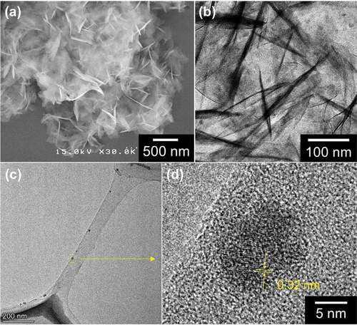
When observing the TEM image of the supernatant solution obtained in the same pot as the powder synthesis, there were carbon dots with a size of about 10 nm, as shown in ). Furthermore, from the high-resolution TEM image shown in ), a lattice fringe with d-spacing of 0.32 nm was observed in a C-dot, which corresponds to the (002) plane of the disordered graphitic structure found in typical C-dots [Citation21,Citation22]. This supernatant C-dots solution exhibits fluorescence peaked at 440 nm, independent of the excitation wavelength (Supporting information, Figure S1a). From these results, it is reasonable to consider that the particles of about 10 nm contained in hydrozincite nanosheets observed in ) are of the same substances as the C-dots obtained in the supernatant solution. Due to the interaction between the C-dots and the hydrozincite, the crystal structure of hydrozincite was partially disturbed, and the surface functional groups of C-dots were interacted with the (CO3)2– sites of hydrozincite. Consequently, the one-pot synthesis gave rise to the synthesis of hydrozincite nanosheets with incorporated and immobilized C-dots.
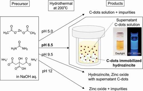
In the present hydrothermal system of the precursor starting from zinc acetate, urea and diammonium hydrogen citrate, the pH of the precursor controlled by NaOH addition is one of the critical parameters for the products after hydrothermal treatment. Depending on the pH of the precursor, the final products change using the same precursor except for NaOH concentration as shown in and Figure S2. Under the pH of the precursor at around 5 without using NaOH, a yellowish C-dots solution was mainly produced, which exhibits a blue emission by UV excitation, and zinc-derived products were hardly precipitated. When the pH of the precursor exceeds around 7, white precipitate, Zn(OH)2, was formed in the precursor, and the hydrozincite was produced after hydrothermal treatment. Therefore, it is considered that the precursor should contain Zn(OH)2 source for the formation of hydrozincite, and it is difficult to precipitate zinc compounds below pH 7 in this hydrothermal reaction. On the other hand, when the pH of the precursor exceeds 9, zinc oxide begins to be produced together with hydrozincite by the hydrothermal reaction. When the pH of the precursor reaches 12, zinc oxide alone is precipitated after hydrothermal treatment without any other products, such as hydrozincite and yellowish solution derived from citrate acid and urea. From these results, only in a specific precursor environment near pH 8.5, the hydrothermal reaction leads to the formation of both the hydrozincite from Zn(OH)2 and urea and the C-dots by developing the carbon network through the reaction with citrate and urea. Also, some of the products would interact at this pH resulting in the formation of C-dots immobilized hydrozincite in the same pot.
Figure 4. Schematic of the products through the hydrothermal synthesis depending on the pH of the precursor
3.2. Photoluminescence properties of carbon-dots-immobilized hydrozincite nanocomposite
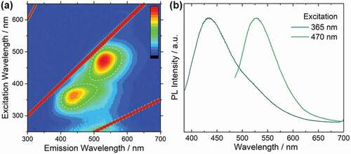
The photoluminescence mapping (excitation-emission-intensity) of the C-dots immobilized hydrozincite is shown in ). Two fluorescent components were observed; the emission peak near 435 nm excited at 365 nm, and the emission peak near 530 nm excited at 470 nm ()). It should be noted that the photoluminescence characteristics of the C-dots immobilized hydrozincite powder are different from those of the C-dots in the supernatant solution obtained in the same pot. The supernatant C-dots solution shows an emission near 440 nm, which is independent of the excitation wavelength (Figure S1a). On the other hand, the C-dots immobilized hydrozincite shows excitation-dependent emission behavior; emission near 530 nm was observed by longer excitation, in addition to emission near 435 nm derived from the pristine C-dots solution by shorter excitation. Since the hydrozincite powder, prepared for comparison using zinc acetate and urea, does not exhibit fluorescence, as shown in Figure S1b. Therefore, the origin of the 530 nm emission is considered to be the change in polarization state on the surface of C-dots by the immobilization of C-dots in hydrozincite matrix. The photoluminescence quantum yield (PLQY) in the C-dots immobilized hydrozincite powder measured using an integrating sphere for the two fluorescence components excited at 365 nm and 470 nm, were 9.6% and 11%, respectively. The PLQY is relatively high considering that the sample is a solid-state composite material containing C-dots, suggesting that there is little influence of the aggregation and reabsorption of C-dots in the hydrozincite matrix and that C-dots might be dispersed and immobilized into the solid matrix [Citation6].
Figure 5. (a) Photoluminescence mapping (Excitation–Emission–Intensity) and (b) Emission spectra excited at 365 nm and 470 nm of the C-dots immobilized hydrozincite powder
3.3. Conversion of carbon dots–hydrozincite nanocomposite into carbon dots–zinc oxide nanocomposite
It is known that hydrozincite undergoes a structural change into zinc oxide at around 250°C [Citation9,Citation23]. In order to obtain the carbon dots–zinc oxide nanocomposite, the C-dots-immobilized hydrozincite was further sintered in air at 255°C for 30 min taking the thermal durability of the carbon dots into consideration.
The XRD pattern of the sintered powder in ) shows that the hydrozincite was partially converted into zinc oxide. The unmarked peaks were assigned to the original hydrozincite. It was revealed that the structural change from hydrozincite to zinc oxide proceeded by just sintering at 255°C.
Figure 6. (a) XRD pattern of the sintered powder at 255°C assigned to zinc oxide by circular marks. (b) Photoluminescence mapping (Excitation–Emission–Intensity) of the sintered powder
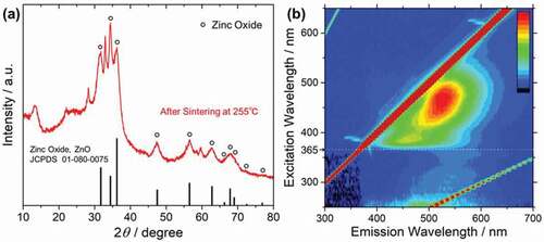
The photoluminescence properties of the sintered powder were also measured, as shown in ). At more than 365 nm excitation wavelength a broad emission at around 400–600 nm was observed, which is the characteristic of the C-dots fluorescence, suggesting the retaining of C-dots in the zinc oxide matrix. On the other hand, at less than 365 nm excitation wavelength a sharp emission peak near 385 nm was observed, suggesting the fluorescence derived from the near band edge emission of semiconductive zinc oxide. In contrast to the photoluminescence mapping of the powder before sintering, the emission at around 430 nm derived from C-dots was quenched in the excitation region of 300–365 nm, and only the emissions from zinc oxide, which are near band edge emission and the defect-level emission, were observed. This suggests that the quenching of C-dots would be attributed to the FRET between C-dots and zinc oxide [Citation24]. Among the absorbed light by the C-dots, a higher energy than the zinc oxide band gap of 3.37 eV (368 nm) is transferred into zinc oxide, and zinc oxide produces luminescence [Citation25]. On the other hand, the lower energy of the absorbed light by the C-dots than the zinc oxide band gap is not transferred and produces luminescence by themselves. Therefore, the broad emission at around 400–600 nm by C-dots fluorescence with matrix is not affected by FRET. Photoluminescence mapping showed the characteristic emission of both C-dots and zinc oxide, confirming the C-dots–zinc oxide nanocomposite fluorescent materials. The PLQY for the C-dots–zinc oxide nanocomposite powder excited at 470 nm was 2.2%. Possible reasons for the decrease in PLQY include deactivation during FRET and reabsorption by zinc oxide.
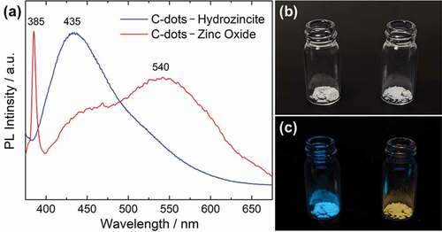
) shows a comparison of the photoluminescence spectra of the nanocomposites between the C-dots–hydrozincite powder and the sintered C-dots–zinc oxide powder, excited at 365 nm. Regarding the C-dots–hydrozincite nanocomposite, only the 435 nm emission derived from C-dots was observed. In the case of C-dots–zinc oxide nanocomposite, a sharp UV range emission at 385 nm derived from the direct transition of zinc oxide and a broad emission at around 540 nm derived from the defect-level emission were mainly observed [Citation26], and a weak shoulder at around 445 nm from C-dots was also observed. The thermal stability of C-dots by sintering at 255°C has been confirmed, and there is no significant change in emission wavelength from the original C-dots (Figure S3). From the spectra, the sintered nanocomposite powder reflects the photoluminescent characteristics of both C-dots and zinc oxide. Both as-prepared and sintered nanocomposites are white powders under the daylight, as shown in ), but when illuminated with a 365 nm UV lamp, the C-dots–hydrozincite nanocomposite emits blue lighting and the C-dots–zinc oxide nanocomposite emits yellow lighting, as shown in ). By sintering and converting into zinc oxide, it enables changing the emission color drastically for the nanocomposite powder. The C-dots–hydrozincite nanocomposite is expected to be applied as an advanced inorganic fluorescent materials exhibiting various fluorescence characteristics by utilizing the host–guest interaction and converting them into zinc oxide.
Figure 7. (a) Photoluminescence spectra of C-dots–hydrozincite nanocomposite and C-dots–zinc oxide nanocomposite excited at 365 nm. The appearance of the C-dots–hydrozincite powder (left) and the C-dots–zinc oxide powder (right) under (b) daylight and (c) UV 365 nm lamp illumination
4. Conclusion
One-pot hydrothermal synthesis enabled the simultaneous preparation of fluorescent carbon dots and layered hydrozincite considering the formation criteria at different pH and interactions of each substance in the reaction solution. Furthermore, the interaction during the hydrothermal reaction achieved the immobilization of carbon dots in the layered hydrozincite nanosheets. An important approach to immobilize the nanocarbons into the inorganic matrix has been demonstrated. It is beneficial to take advantage of the interaction of carbonate groups in the layered hydroxide structures with the various functional groups in C-dots to develop materials that have the potentials to exhibit excellent physical properties for suitable electrodes, lightings and catalysts applications. The photoluminescence quantum yield of the hydrozincite–C-dots nanocomposite powder suggested that C-dots are immobilized, and highly dispersed and stable in the solid matrix. Furthermore, the sintering of the hydrozincite nanocomposite under appropriate conditions enabled it to convert into zinc oxide while retaining the carbon dots in the matrix. The obtained C-dots-incorporated zinc oxide exhibits multiple fluorescence characteristics reflecting another fluorescence from zinc oxide besides carbon dots, different from the one before sintering. The findings of the one-pot nanocomposite synthesis obtained in the present study can be further applied as a useful approach especially for incorporating and immobilizing nanocarbon materials in layered compounds and compositing nanocarbons with dispersed state in semiconducting oxides.
Supplemental Material
Download PDF (523.5 KB)Acknowledgments
The authors would like to acknowledge Dr. Shohei Ida and Dr. Tsuyoshi Akiyama in the University of Shiga Prefecture and Mr. Kazuki Sobue at the Shimadzu Corporation for their assistance in photoluminescence measurements.
Disclosure statement
No potential conflict of interest was reported by the authors.
Supplementary material
Supplemental data for this article can be accessed here
Additional information
Funding
References
- Yu H, Zhang H, Huang H, et al. ZnO/carbon quantum dots nanocomposites: one-step fabrication and superior photocatalytic ability for toxic gas degradation under visible light at room temperature. New J Chem. 2012;36:1031–1035.
- Khan F, Akhtar N, Jalal N, et al. Carbon-dot wrapped ZnO nanoparticle-based photoelectrochemical sensor for selective monitoring of H2O2 released from cancer cells. Mikrochim Acta. 2019;186:127.
- Efa MT, Imae T. Effects of carbon dots on ZnO nanoparticle-based dye-sensitized solar cells. Electrochim Acta. 2019;303:204–210.
- Barman MK, Mitra P, Bera R, et al. An efficient charge separation and photocurrent generation in the carbon dot–zinc oxide nanoparticle composite. Nanoscale. 2017;9:6791–6799.
- Suzuki K, Takahashi M, Malfatti L, et al. Carbon dots in ZnO macroporous films with controlled photoluminescence through defects engineering. RSC Adv. 2016;6:55393–55400.
- Shao J, Zhu S, Liu H, et al. Full-color emission polymer carbon dots with quench-resistant solid-state fluorescence. Adv Sci. 2017;4:1700395.
- Bozetine H, Wang Q, Barras A, et al. Green chemistry approach for the synthesis of ZnO-carbon dots nanocomposites with good photocatalytic properties under visible light. J Colloid Interface Sci. 2016;465:286–294.
- Liang H, Tai X, Du Z, et al. Enhanced photocatalytic activity of ZnO sensitized by carbon quantum dots and application in phenol wastewater. Opt Mater. 2020;100:109674.
- Kanari N, Mishra D, Gaballah I, et al. Thermal decomposition of zinc carbonate hydroxide. Thermochim acta. 2004;410:93–100.
- Zhu S, Song Y, Zhao X, et al. The photoluminescence mechanism in carbon dots (graphene quantum dots, carbon nanodots and polymer dots): current state and future perspective. Nano Res. 2015;8:355–381.
- Ghose S. The crystal structure of hydrozincite, Zn5(OH)6(CO3)2. Acta Cryst. 1964;17:1051–1057.
- Carbajal-Arizaga GG, Satyanarayana KG, Wypych F. Layered hydroxide salts: synthesis, properties and potential applications. Solid State Ion. 2007;178:1143–1162.
- Wahab R, Ansari SG, Kim YS, et al. Synthesis and characterization of hydrozincite and its conversion into zinc oxide nanoparticles. J Alloys Compd. 2008;461:66–71.
- Zhang Y, Jing N, Zhang J, et al. Hydrothermal synthesis of nitrogen-doped carbon dots as a sensitive fluorescent probe for the rapid, selective determination of Hg2+. Int J Environ Anal Chem. 2017;97:841–853.
- Khan WU, Wang D, Zhang W, et al. High quantum yield green-emitting carbon dots for Fe(ІІІ) detection, biocompatible fluorescent ink and cellular imaging. Sci Rep. 2017;7:14866.
- Miao X, Qu D, Yang D, et al. Synthesis of carbon dots with multiple color emission by controlled graphitization and surface functionalization. Adv Mater. 2017;30:1704740.
- Kasprzyk W, Świergosz T, Bednarz S, et al. Luminescence phenomena of carbon dots derived from citric acid and urea – a molecular insight. Nanoscale. 2018;10:13889–13894.
- Hales MC, Frost RL. Synthesis and vibrational spectroscopic characterisation of synthetic hydrozincite and smithsonite. Polyhedron. 2007;26:4955–4962.
- Bucca M, Dietzel M, Tang J, et al. Nucleation and crystallization of otavite, witherite, calcite, strontianite, hydrozincite, and hydrocerussite by CO2 membrane diffusion technique. Chem Geol. 2009;266:143–156.
- Wang M, Zhao B, Xu S, et al. Synthesis of hierarchically structured ZnO nanomaterials via a supercritical assisted solvothermal process. Chem Commun. 2014;50:930–932.
- Li H, He X, Kang Z, et al. Water-soluble fluorescent carbon quantum dots and photocatalyst design. Angew Chem Int Ed. 2010;49:4430–4434.
- Yang Z-C, Wang M, Yong AM, et al. Intrinsically fluorescent carbon dots with tunable emission derived from hydrothermal treatment of glucose in the presence of monopotassium phosphate. Chem Commun. 2011;47:11615–11617.
- Bitenc M, Marinšek M, Orel ZC. Preparation and characterization of zinc hydroxide carbonate and porous zinc oxide particles. J Eur Ceram Soc. 2008;28:2915–2921.
- Bharathi D, Hari Krishna R, Singh V, et al. One pot synthesis of C-dots and study on its interaction with nano ZnO through fluorescence quenching. J Lumin. 2017;190:328–334.
- Wang ZL. Zinc oxide nanostructures: growth, properties and applications. J Phys Condens Matter. 2004;16:R829–R858.
- Suzuki K, Malfatti L, Carboni D, et al. Energy transfer induced by carbon quantum dots in porous zinc oxide nanocomposite films. J Phys Chem C. 2015;119:2837–2843.