
 ?Mathematical formulae have been encoded as MathML and are displayed in this HTML version using MathJax in order to improve their display. Uncheck the box to turn MathJax off. This feature requires Javascript. Click on a formula to zoom.
ABSTRACT
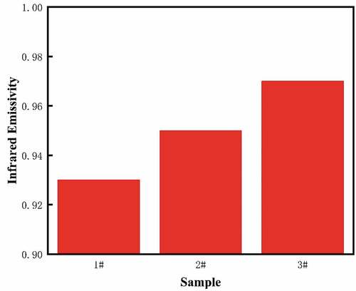
Infrared temperature measurement is widely used in the MOCVD process, and improving the surface infrared emissivity of the graphite base is beneficial to improve the temperature measurement accuracy. In this study, SiC coatings were prepared by CVD on graphite substrate using different process parameters including CVD temperature, total pressure, H2/MTS ratio. The infrared emissivity of SiC coatings with different microstructures was investigated. All SiC coatings obtained were β-SiC. The infrared emissivities of the three samples with different surface morphologies are 0.93, 0.95 and 0.97, respectively. As the surface roughness increases, the reflection and scattering of thermally radiated electromagnetic waves increases, resulting in higher infrared emissivity. The loose structure of the grain surface makes the surface electromagnetic wave and light wave resonant coupling, thus increasing the infrared emissivity.
1. Introduction
The group-III nitrides such as gallium nitride, aluminum gallium nitride and indium gallium nitride are widely used in the LED industry [Citation1–4]. MOCVD is the main way to prepare group–III nitrides [Citation5–8]. During the deposition process, the temperature and its distribution in the reaction chamber are important process parameters for MOCVD epitaxial growth, which affects the crystal quality of the epitaxial layer, as well as the performance of the final device. For example, in the indium-doped process of growing InGaN/GaN MQW LED epitaxial wafers on Si(111) substrates, every 1°C deviation in temperature will eventually cause the center wavelength of the device to shift by about 1–2 nm [Citation9]. In-situ infrared temperature measurement can perform real-time, whole-process nondestructive monitoring of the surface temperature of the graphite disc during the epitaxial growth process, which can timely understand the temperature change in the reaction chamber, optimize the process, avoid waste products, and improve product yield.
However, the measurement accuracy of infrared thermometry is affected by many factors, and one of the most important that is the surface emissivity. In view of the influence of surface emissivity on the accuracy of infrared temperature measurement, domestic and foreign scholars have done a lot of work [Citation10–15]. It is generally believed that high emissivity is conducive to improving the temperature measurement accuracy.
Therefore, in order to improve the infrared temperature measurement accuracy in the MOCVD process, it is necessary to improve the surface emissivity of the graphite base. The graphite base consists of a graphite matrix and a silicon carbide coating. The silicon carbide coating has an important effect on the surface emissivity. The previous studies had proved that the infrared emissivity of materials was markedly affected by surface conditions, such as chemical composition, coating thickness and surface morphology [Citation16]. Fuyuan Wang et al. found that SiC coating had an obvious effect on the spectral emissivity of the C/SiC composites because the SiC coating changes the surface chemical composition and surface morphology [Citation17]. In addition, they also found that surface microstructures had a great effect on the normal emissivity of graphite, and the normal emissivity is reduced with an increase of the smooth [Citation18]. However, little research has been done on the effect of SiC coating microstructure on emissivity.
In this paper, the infrared emissivity of CVD SiC coatings with different microstructure were probed. The relation between microstructure and surface topography was focused. The conclusions of this study can be used to improve the infrared temperature measurement accuracy in the MOCVD process.
2. Experimental procedures
2.1. Material preparation
Low pressure chemical vapor deposition was used to prepare CVD SiC coatings. SiC was deposited on polished graphite substrates which was machined to φ30 mm × 2 mm. CH3SiCl3, H2 and Ar were used to prepare SiC coatings according to the following reaction [Citation19]:
Industrial vertical chemical vapor deposition equipment () is used to prepare silicon carbide coatings. The device is 1.2 m in diameter and 2 m high. The gas flows in uniformly from the five gas inlets, and flows out from the bottom gas outlet after the reaction. A two-layer workwear is placed on a rotating platform, which rotates at a speed of 0.5 r/min to improve the uniformity of deposition. The samples prepared in this study were placed on the first layer of the workwear for coating preparation. Three kinds of SiC coatings were fabricated. The detailed information of the deposition parameters has been listed in .
Figure 1. Schematic diagram of CVD reactor.
Table 1. Deposition parameters.
2.2. Coating characterization
Macro morphology and surface roughness were characterized by optical profiler (White Light Interferometer). The surface morphology and microstructure of the coatings were analyzed using a scanning electron microscopy. The phase composition and orientation were studied by a Smartlab 9 kw X-ray diffractometer (Cu Ka radiation, wavelength 0.15406 nm, voltage 40 KV, current 40 mA).
2.3. Emissivity measurements
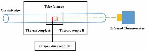
The emissivity test device includes a tubular resistance furnace and an infrared thermometer. The tubular resistance furnace mainly includes a high-temperature heating system and a program control system. The maximum temperature in the cavity of the tubular resistance furnace can reach 1400°C, and the temperature and heating rate in the cavity can be precisely controlled to meet the needs of the experimental samples to be tested at different temperatures. The heating element in the cavity is a silicon molybdenum rod. It has unique high-temperature oxidation resistance. The temperature in the furnace is measured by platinum-rhodium B-type thermocouple and precision digital display temperature controller, and the temperature control accuracy is ±1°C. The infrared thermometer used is MR1SBSF produced by Raytak Company.
As shows, the sample was placed in a tube furnace, and the temperature was raised to a specified temperature of 800°C with the furnace. We put the calibrated thermocouples A and B on the left and right sides of the sample, then adjust the position of the sample to make the temperature difference between A, B and the specified temperature within ±3°C and stable for 10 minutes. After holding for 30 minutes, use an infrared thermometer to align the center of the test piece, adjust the emissivity so that the measurement temperature is 800°C, and record the emissivity. Average emissivity was obtained after five measurements for each sample.
Figure 2. Schematic diagram of infrared emissivity calibration process.
3. Results and discussions
3.1. Microstructure characterization
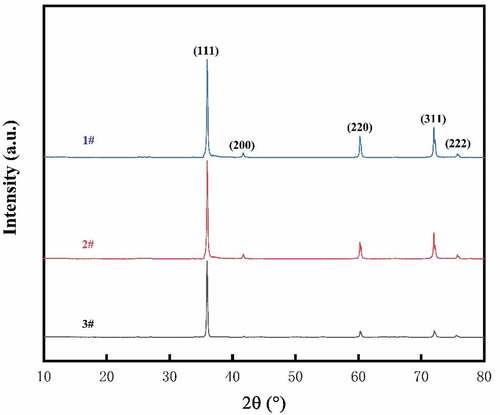
The XRD results () show that the composition of the coatings of the three samples is all β-SiC, and all show (111) preferred orientation.
Figure 3. X-ray diffraction spectra of SiC coatings.
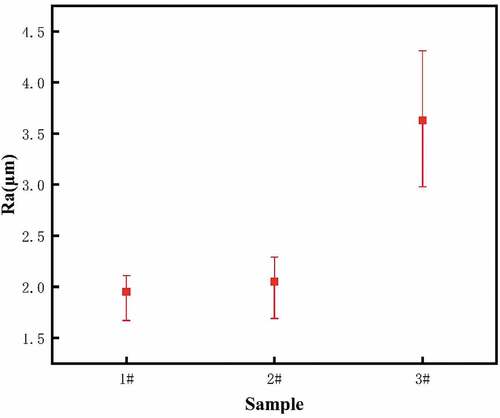
shows the three-dimensional morphologies of the three samples. It can be clearly seen that there are obvious fluctuations on the surfaces of the three samples. In order to further compare the fluctuation degree of the three, the average roughness (Ra) of the coating surface was characterized and compared (). The results show that the average roughness of sample 3# are much higher than those of sample 1# and sample 2#.
Figure 4. Three-dimensional topography of SiC coatings.
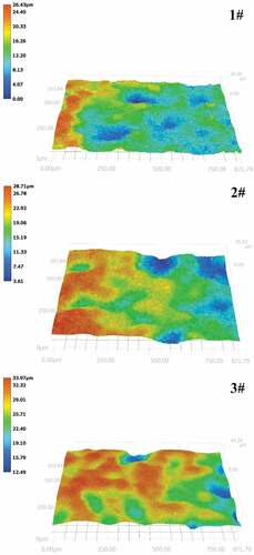
Figure 5. Average roughness of SiC coatings.
In order to further compare the surface morphologies of the three samples., SEM characterization was performed (). It could be seen that both samples exhibit a pyramidal morphology, which is typical morphology of SiC coatings at high preparation temperatures. It can be clearly seen that the surface of sample 3# has a more complex and undulating topography. For sample 2# and 3#, some differences can be seen at higher multiples. The grain surface of sample 1# is dense and smooth, while the grain surface of sample 2# is loose and rough. This may be due to the relatively lower preparation temperature and higher supersaturation of reactants (lower ratio of H2 to MTS) compared with sample 1#, resulting in a faster nucleation rate and a weaker mobility of molecules on the surface.
Figure 6. SEM images of SiC coatings.
Figure 7. Infrared emissivity of SiC coatings.
3.2. Infrared emissivity
shows the high-temperature emissivity test results for the three samples. The emissivity of all three samples is high and shows an increasing trend.
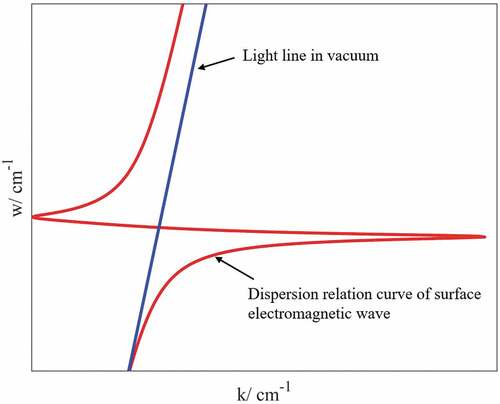
Figure 8. Dispersion relation curve of light wave propagation in vacuum and surface electromagnetic wave on SiC surface.
For the three samples studied in this paper, the surface chemical composition and coating thickness are the same, so the difference in the emissivity of the samples is mainly affected by the surface morphology. The material surface can be divided into macro-rough surface and micro-rough surface. Thermal radiation performance electromagnetic waves only have a macroscopic effect on the macroscopic surface, and its effect on thermal radiation electromagnetic waves can be explained by geometric optics. For microscopic rough surfaces, the surface electromagnetic wave scattering properties have only been studied in the last decade. Electromagnetic waves interact with microscopically rough surfaces to alter their scattering and radiation properties. Therefore, the interaction between the rough surface and the thermal radiation electromagnetic wave is mainly developed from the macroscopic and microscopic aspects.
From a macroscopic point of view, the diffraction, interference and surface polarization of electromagnetic waves on the surface are ignored, and the geometrical optics method is generally used to study the effect of rough surfaces on thermal radiation electromagnetic waves [Citation20,Citation21]. For the samples composed of the same material, the relationship between surface roughness and emissivity:
where εr and εk represent the emissivity of samples with different surface roughness, Rr and Rk indicates surface roughness of different samples.
It is obvious that the infrared emissivity gradually increases with the increase of the surface roughness of the sample. Further analysis shows that the thermal radiation energy generated by the sample is essentially infrared electromagnetic wave. When an electromagnetic wave propagates on the surface of the specimen and encounters small slopes or pits protruding from the surface, it will be reflected and scattered. During the interaction between the electromagnetic wave and the surface topography, a part of the energy carried by the electromagnetic wave is absorbed by the surface of the sample, which increases the absorption rate of the surface of the sample. According to Kirchhoff’s law, the absorption rate of an object in thermal equilibrium is equal to its emissivity, so the multiple reflection and scattering of electromagnetic waves are beneficial to the improvement of the infrared emissivity of the sample. For the samples in this study, sample 3# has significantly higher roughness, which means more surface chamfers and pits, and a greater degree of undulation. When the thermal radiation electromagnetic wave propagates on the rough surface of the sample, these slopes and pits will reflect and scatter the electromagnetic wave multiple times, increase the absorption and scattering of thermal radiation energy, and improve the emissivity.
When analyzing micro-rough surface, surface electromagnetic wave should be considered. For semiconductors, surface electromagnetic waves existing on the surface are called surface phonon polaritons (SPhPs). The dispersion relation of SPhPs at the interface between silicon carbide and vacuum:
where k is wave number, ε represent the dielectric constant of silicon carbide, c is light speed and is frequency.
The dispersion relation curve can also be obtained according to the dispersion relation. shows the dispersion relation curve of light wave propagation in vacuum and the dispersion relation curve of surface electromagnetic wave on SiC surface. The upper branch is a longitudinal optical phonon curve, and the lower branch is a transverse optical phonon curve. Light wave is transverse wave and can only be resonant coupled with transverse optical phonons. So only the lower branch can be considered in the study of dispersion relation curve of light wave and surface electromagnetic wave. In general, the wave vectors of the two do not intersect, and the surface electromagnetic wave will not be coupled with the light wave. In our study, the loose structure on the grain surface of sample 2 # can be regarded as periodically arranged nanoparticles. When the surface electromagnetic wave propagates along the surface, it will couple with the nano particles, resulting in its dispersion relationship becoming:
where m is diffraction order and is period.
When m is negative, the dispersion curve of the surface electromagnetic wave will shift to the left, generating an intersection point with the light wave. At the wavelength corresponding to the intersection point, the light wave will resonant couple with the surface electromagnetic wave, resulting in the peak of the emission spectrum. Therefore, sample 2 # has a higher emissivity than sample 1 #.
4. Conclusions
In this paper, the relationship between the surface microstructure and infrared emissivity of SiC coatings was investigated. The main conclusions of this study are as follows:
(1) The surface roughness has an important influence on the infrared emissivity. As the surface roughness increases, the reflection and scattering of thermally radiated electromagnetic waves increases, resulting in higher infrared emissivity.
(2) The microstructure of the grain surface also significantly affects the infrared emissivity. The loose structure of the grain surface changes the dispersion relationship of surface electromagnetic waves, which leads to resonant coupling between light waves and surface electromagnetic waves at specific wavelengths and results in emission spectrum peaks and improved emissivity.
Acknowledgments
This research work was supported by the National Natural Science Foundation of China (Grant No. 92160202), and Priority Academic Program Development of Jiangsu Higher Education Institutions (PAPD).
Disclosure statement
No potential conflict of interest was reported by the author(s).
Additional information
Funding
References
- Nakamura S, Fasol G, Pearton SJ. The Blue Laser Diode:The Complete Story. Berlin: Springer; 2000.
- Schubert EF. Light-Emitting Diodes. Cambridge: Cambridge University Press; 2006.
- Haitz R, Kish F, Tsao J, et al. The case for a national research program on semiconductor lighting (white paper presented at the Optoelectronics Industry Development Association. Washington DC: Sandia National Laboratories Technical Report SAND 2000—1612; 1999.
- Krames MR, Shchekin OB, Mueller-Mach R, et al. Status and future of high-power light-emitting diodes for solid-state lighting. J Display Technol. 2007;3(2):160.
- Han J, Figiel JJ, Crawford MH, et al. OMVPE growth and gas-phase reactions of AlGaN for UV emitters. J Cryst Growth. 1998;195(1—4):291.
- Chen CH, Liu H, Steigerwald D, et al. A study of parasitic reactions between NH3 and TMGa or TMAI. J Electron Mater. 1996;25(6):1004.
- Sayyah K, Chung B-C, Gershenzon M. The influence of TMA and SiH4 on the incorporation rate of Ga in AlxGa1− xN crystals grown from TMG and NH3. J Cryst Growth. 1986;77(1—3):424.
- Nakamura F, Hashimoto S, Hara M, et al. AlN and AlGaN growth using low-pressure metalorganic chemical vapor deposition. Journal of Crystal Growth. 1998;195(1—4):280.
- Creighton JR, Koleske DD, Mitchell CC. Emissivity-correcting near-UV pyrometry for group-III nitride OMVPE. J Cryst Growth. 2006;287(2):572.
- García-Santos V, Coll C, Valor E, et al. Analyzing the anisotropy of thermal infrared emissivity over arid regions using a new MODIS land surface temperature and emissive product (MOD21. Remote Sens Environ. 2015;169:212–221.
- Zhang K, Jiao L, Zhao X, et al. An instantaneous approach for determining the infrared emissivity of swine surface and the influencing factors. J Therm Biol. 2016;57:78–83.
- Sobrino JA, Jiménez-Muñoz JC. Minimum configuration of thermal infrared bands for land surface temperature and emissivity estimation in the context of potential future missions. Remote Sens Environ. 2014;148:158–167.
- Rodiet C, Remy B, Degiovanni A. Optimal wavelengths obtained from laws analogous to the Wien’s law for monospectral and bispectral methods, and general methodology for multispectral temperature measurements taking into account global transfer function including non-uniform emissivity of surfaces. Infrared Phys Technpl. 2016;76:444–454.
- Zhang YC, Chen YM, Luo C. A method for improving temperature measurement precision on the uncooled infrared thermal imager. Measurement. 2015;74:64–69.
- Guan SH, WANG BY, ZHAO WL, et al., Study of Temperature Measurement Precision Base on Infrared Thermal Imager. Electro-opt Tech Appl. 2012;27(3):85–88.
- Huang Z, Zhou W, Tang X, et al. Effects of substrate roughness on infrared-emissivity characteristics of Au films deposited on Ni alloy. Thin Solid Films. 2011;519(10):3100–3106.
- Wang F, Cheng L, Zhang Q, et al. Effect of surface morphology and densification on the infrared emissivity of C/SiC composites. Appl Surf Sci. 2014;313:670–676.
- Wang F, Cheng L, Mei H, et al. Effect of Surface Microstructures on the Infrared Emissivity of Graphite. Int J Thermophys. 2014;35(1):62–75.
- Liu J, Chen Z, Chai P, et al. The effect of deposition temperature on microstructure and mechanical properties of SiC coatings on graphite. J Aust Ceram Soc. 2022;55(2):557–562.
- Agababov SG. Effect of the roughness of the surface of a solid body on its radiation properties and methods for their experimental determination. High Temp. 1968;6:76–85.
- Wen CD, Mudawar I. Modeling the effects of surface roughness on the emissivity of aluminum alloys. Int J Heat Mass Transfer. 2006;49(23—24):4279–4289.