
 ?Mathematical formulae have been encoded as MathML and are displayed in this HTML version using MathJax in order to improve their display. Uncheck the box to turn MathJax off. This feature requires Javascript. Click on a formula to zoom.
Abstract
This paper develops protection principles for a serial multi-terminal DC grid. The difference between conventional HVDC systems and serial multi-terminal DC grids from protection aspect is analyzed. The problem of conventional protection principle applied in serial multi-terminal DC grid has been investigated. In order to supply main and back up protection with high reliability, high sensitivity and fast operation speed, a travelling wave protection algorithm based on the rate of changes in the local measured signals together with modified DC filter configuration is proposed in this paper. Simulation results verified the validity of the proposed solutions.
1. Introduction
The point-to-point HVDC system has been widely used in the world. In the traditional point-to-point HVDC system, travelling wave based protection principle and differential current protection principle are used to detect the fault in the DC transmission line. Travelling wave protection has an obvious advantage which only uses local measurements and has very fast operation speed for most faults. One of the weak point of such protections is that it has relatively low sensitivity for high resistance faults. In general a fault resistance larger than 200 Ω may lead to the failure of operation for the protection system, while lightning may lead to incorrect operation either. The differential current protection which is used as backup protection usually is configured with long delay to avoid possible mal-operation caused by the line distributed capacitance. In addition, the appearance of DC grid brings new requirements for HVDC line protection. Many papers investigated new protection algorithms to improve the performance of conventional HVDC line protection and to meet the requirements of DC grid [Citation1–Citation10].
There are mainly two kinds of HVDC technologies. One is based on line commutated converter (LCC) and the other is based on voltage source converter (VSC). VSC has the advantages of MTDC (multi-terminals DC grid) such as decoupled control of active power and reactive power, etc. However, the higher power rating makes LCC MTDC system almost the only choice for bulk power/long distance applications. Furthermore, series LCC MTDC is a competitive solution for high altitude application because the insulation cost for the converter station and transmission line at high altitude area will be greatly reduced.
DC fault protection is very important for series MTDC system, some papers try to find the solutions to alleviate the impact of faults [Citation11,Citation12]. In order to improve the transmitted energy when a DC fault occurs, different protection zone should be distinguished. Serial multi-terminal HVDC system brings new challenges to the traditional travelling wave based protection. The aim of this paper is to research the protection principle for serial multi-terminal LCC HVDC grid.
This paper sets up a PSCAD based serial four-terminal LCC HVDC grid model, and the performance of conventional protection principles in serial multi-terminals DC grid has been simulated. The simulation results show that the conventional travelling wave protection will fail to operate or mal-trip in the series MTDC system conditions because the travelling wave created by the external fault will not flow through the smoothing reactor in a series MTDC system. The assumption for the conventional travelling wave protection that the smoothing reactor can slow down the travelling wave caused by external faults in conventional HVDC does not exist anymore. This paper proposes novel solutions which modify the configuration of DC filter slightly and distinguish internal and external faults according to the change rate of the travelling wave. Simulations based on PSCAD model verify the validity of proposed solution.
2. Review of conventional HVDC line protection
2.1. Conventional travelling wave protection
A conventional travelling wave protection detects the amplitude of the travelling wave front. shows a widely used travelling wave protection principle, which uses three different measurements to determinate the fault. Paper [Citation3] indicates that the conventional travelling wave protection may fail-to-operate when a fault with high resistance occurs. It also may mal-operate when a lightning occurs, while there is no fault in the line.
Figure 1. Conventional travelling wave protection.
2.2. Conventional differential current protection
Conventional differential current protection is used as backup protection in existing HVDC system. A typical criterion of the differential current protection is shown below,
In which I
Local
is the current of local side while is the current of remote side, as shown in . The differential protection is seriously influenced by distributed capacitance along the line ().
Figure 2. Model with internal & external fault.
From above figure, we have Equation (2) which is valid during normal load and external fault conditions:
where, is the capacitive current along the line. In order to avoid mal-operation, conventional differential current protection uses long time delay because
only exists temporarily after faults, so the response speed is slowed down.
3. Features of fault in serial multi-terminal DC grid and impacts on conventional protection
3.1. Difference between traditional HVDC system and serial multi-terminal DC grid
In this paper, a serial four terminals LCC DC grid shown in is established to study the difference between traditional HVDC system and serial multi-terminal DC grid. (a) shows the serial four terminals bi-pole DC grid model; (b) gives corresponding single line model for better understanding.
Figure 3. Serial four terminals DC grid.
As shown in (b), there are four converter stations including Rectifier1, Rectifer2, Inverter1 and Inverter2; and there are three double-pole lines, L1, L2 and L3. L1 represents the transmission line connecting Rectifier 1 to Rectifier 2, 500 km in length with voltage level 400 kV; L2 represents the 1000 km length, 800 kV transmission line connecting Rectifier 2 and Inverter 2; L3 represents the 500 km, 400 kV transmission line connecting Inverter 2 and Inverter 1. F1~F13 are fault locations to verify the proposed solutions which will be introduced in section 6. The study shows that the series MTDC is different from two terminal HVDC systems in many ways such as fault types, travelling wave path, fault location, control, voltage levels, etc.
From the fault type aspect, there are only two kinds of faults including internal DC faults and external AC faults in the conventional HVDC system; while in serial multi-terminal DC grid, there is another kind of faults, i.e. external DC faults. As shown in , F4–F9 are external DC faults for the protection relays of L1.
From the travelling wave path aspect, in the conventional HVDC system, travelling wave from external faults will flow through the smoothing reactor; while in a serial multi-terminal DC grid, travelling wave from external faults may not flow through the smoothing reactor. Such a situation will be introduced in details later.
From the fault location aspect, in the conventional HVDC system, internal DC faults must lie between a rectifier station and an inverter station. While in serial multi-terminal DC grid, the faults may be located between two rectifier stations or two inverter stations. For example, F1–F3 are located between rectifier station 1 and station 2; and F7–F9 are located between two inverter stations.
From HVDC control strategy aspect, the control in conventional HVDC system is relatively simple; while the control strategy in serial multi-terminal DC grid is very complex. For example, different from conventional HVDC system, two converter stations may be out of operation in case of DC faults while the other two will still be in operation to maintain the power transmission.
From voltage level aspect, serial multi-terminal DC grid may have two or more voltage levels; while there is only one voltage level in traditional HVDC system. For example, in the model shown in , there are two voltage levels including 400 and 800 kV.
The difference between conventional HVDC system and serial multi-terminal DC grid is summarized in , which will obviously directly influence the fault characteristic and protection.
Table 1. Comparison of classical HVDC system and LCC DC Grid.
From , it can be seen that the protection for serial multi-terminal DC grid is a new thing which need to be investigated.
3.2. Issues of travelling wave protection when used in serial multi-terminal DC grid
A conventional travelling wave based protection shown in is based on the physical feature of the smoothing reactor in HVDC system which can slow down the change rate of travelling wave caused by external faults. For series MTDC system, the travelling wave caused by external faults will not flow through the smoothing reactor so that the travelling wave protection will fail to operate or mal-operate.
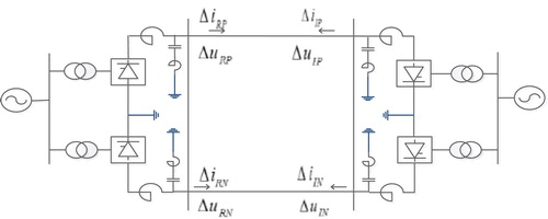
For example, (a) shows the DC filter from Xiangjiaba-Shanghai 800 kV HVDC project and (b) demonstrates the partial grid in (a) including Rectifer1 and Rectifer2.
Figure 4. Path of the travelling waves from internal and external faults in serial multi-terminal DC grid.
It can be seen from (a) that the DC filter can be regarded as a capacitance for high frequency components; from (b), we know that smoothing reactor is not in the travelling path of DC faults. For example, considering the protection unit Relay1, F3 is the internal fault while F4 is the external fault. It can be seen that the travelling wave caused by fault F4 will flow through DC filter directly and travel to Relay1. As the line L2 is with higher voltage, for Relay1, the travelling wave caused by external fault F4 will be much larger than that caused by internal fault F3. As a result, the conventional travelling wave protection cannot distinguish internal fault F3 from external fault F4.
shows the simulated travelling wave observed by Relay1. It is very clear in that the change rate of the wave fronts from the internal fault and the external fault is definitely the same at the beginning. At the same time, the travelling wave front of external fault is even much larger than that of the internal fault, because the external line’s voltage level is higher.
Figure 5. Travelling wave fronts of internal & external DC faults.
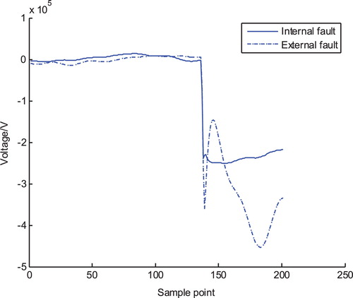
Given that the wave front of the external fault in serial multi-terminal DC grid is even larger than that of the internal fault and the change rate of both internal & external faults is the same, the conventional travelling wave protection will mal-operate in such cases. In other words, existing HVDC travelling wave protection cannot be used directly in the serial multi-terminal LCC DC grid.
4. Novel protection solution
From the above discussion, it is clear that the conventional travelling wave protection cannot be directly applied to the serial multi-terminals DC grid. In order to provide main protection for a serial multi-terminals DC grid with fast operation speed and high sensitivity, the change rate of travelling wave based protection together with a new configuration of a smooth reactor and a DC filter is proposed here.
4.1. Modified smooth reactor and DC filter configuration
A typical practical smooth reactor and a DC filter configuration in a serial multi-terminal DC grid are shown in (a), where the DC filter shows a high-pass characteristic to the traveling wave front.
In order to design main protection based on the travelling wave for the serial multi-terminal DC grid, this paper proposes several new configurations for smooth reactors and DC filters as shown in (a)–(c), or even removes the DC filters as shown in (d), just to ensure the traveling wave from external faults to flow through the smooth reactors so that a relatively slow ramping rate compared to the internal fault could be obtained.
Figure 6. New configurations of smooth reactor and DC filter.
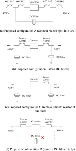
Even with modified DC filter configuration, the amplitude of the travelling wave by external DC faults may still be much larger than those created by internal DC faults because of higher voltage of adjacent lines, so the conventional travelling wave protection still cannot be used. Therefore, this paper proposes a travelling wave change rate based protection.
4.2. Protection principle based on travelling wave change rate
Take a DC grid with system layout shown in as an example; the change rate based protection principle is illustrated as below.
Calculating fault component currents and fault component voltages
Figure 7. Point to point LCC HVDC system model.
In above equations, T is the time delay setting, e.g. 1–10 ms; it depends on the requirements.
Pole-mode transformation
From step (a), pole fault components voltage and currents ,
,
and
are obtained. By this step, the pole fault components will be transformed to mode fault components.
The transformation matrix is shown as below.
Here, and
are the common mode voltage and differential mode voltage respectively.
and
are the common mode current and the differential mode current respectively.
Directional travelling wave calculation
Travelling waves can be resolved to forward direction travelling wave and reverse direction travelling wave. The forward directional differential mode u Fwd1 and the reverse direction travelling wave u Rvs1 can be calculated by the following (6):
Here, u Fwd1 is the forward directional differential mode travelling wave and u Rvs1 is the reverse directional travelling wave.
The common mode signals both for the forward direction travelling wave and the reverse direction travelling wave are given in (7) respectively:
Here, u Fwd0 is the forward common mode directional travelling wave and u Rvs0 is the reverse common mode directional travelling wave.
Fault determination
The 1st derivative is used to distinguish internal fault; when the value of
is larger than a threshold u
set
, an internal fault is determined.
The criterion is:
shows the travelling waves and corresponding change rate of internal faults and external faults under modified DC filter configuration.
Figure 8. Travelling waves and corresponding change rate.
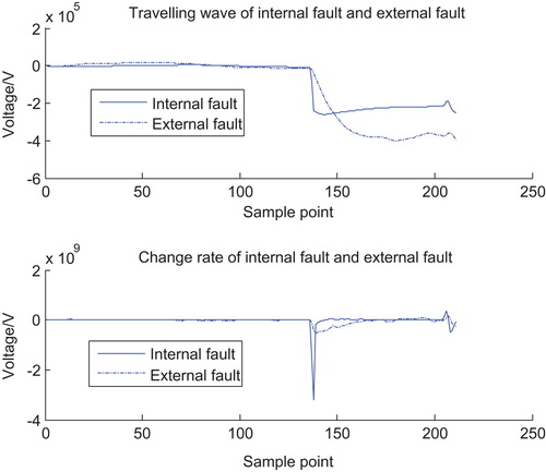
It can be known from that under the condition of modified DC filter, the travelling wave amplitude of external faults is still larger than that of internal fault, but the change rate of the travelling wave by internal fault is much larger than that of the external fault. According to such characteristic, internal faults and external faults can be distinguished reliably.
5. Performance analysis
5.1. High reliability, less influence by lighting
One shortcoming of the conventional travelling wave based protection is that the lightning may cause mal-operations. The protection shown in adds time delay to avoid mal-operation (continuous three sampling points larger than the threshold). Some other protection principles use the integration to avoid the mal-operation, which also introduce the time delay.
The proposed change rate of the travelling wave based protection algorithm can also use such delay to ensure the reliability by considering the lightning wave which is very short. On the other hand, the noise caused by lightning is common mode disturbance, which has very little impact on the differential mode travelling wave used in the new principle.
5.2. High sensitivity
The ability of the classical protection principle based on the travelling wave shown in to detect the high impedance is limited, because it uses the amplitude information to distinguish faults. When a fault with high resistance occurs, the amplitude of travelling wave is decreased, the higher fault impedance is, and the lower amplitude will be, so the traditional principle may fail-to-operate.
The proposed method has high tolerance for high impedance because it is based on change rate of travelling wave. Even when a fault with high resistance occurs, the change rate of the travelling wave is still high enough to be distinguished.
5.3. Wide adaptability and the local information only
The proposed principle can be applied to any kinds of DC systems on the premise that the travelling wave caused by external faults is hindered. We know that the classical point to point HVDC system and VSC based DC grids comply with such a premise, so it can be applied to both kinds of DC systems. This principle only uses local information so that no communication channels are needed.
6. Simulation verification
The simulation model is shown in . Internal DC metal faults, internal high resistance DC faults, external DC fault and external AC faults are simulated to verify the validity of the proposed solution.
There are 13 fault locations set in the model, F1 to F13, in which F1 to F9 are DC fault locations and F10~F13 are the AC fault locations pre-set. Metal faults and high resistance faults have been simulated at these 13 fault locations and both poles to ground faults and pole to pole faults are also simulated. The simulation results show that the proposed protection principles have high reliability and sensitivity.
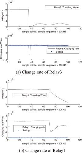
Various faults with different fault resistance and different location are also simulated to verify the travelling wave change rate based protection. In order to make the paper shorter, only partial simulation results are presented here. gives a simulation for change rate based protection when a high resistance fault occurs at F5. It can be seen that Relay 3 can operate correctly because the change rate of the travelling wave detected by Relay 3 is much greater than the setting; while Relay 1 will not operate because it is an external fault whose travelling wave generated is hindered by the reactor. As for the ability to tolerate fault resistance, change rate based protection principle can detect 2000 Ω fault resistance for the 800 kV line L2, while for the line L1 & L3, whose voltage level is 400 kV, the proposed protection principle can cover 500 Ω fault resistance. The reason why the protection for lower voltage line covers less fault resistance is that it must avoid mal-operation because the external fault occurs in the line with higher voltage ratings. When a fault occurs in the line with higher voltage level, the travelling wave is very large, so the protection for lines with lower voltage must use higher voltage threshold. On the other hand, the protection for lines with higher voltage level can cover higher fault resistance. The simulation results also show that this principle has fast operation speed, it can operate for most faults within 1 ms.
Figure 9. Simulation result for travelling wave change rate based protection.
7. Conclusion
In this paper, the difference between the conventional HVDC system and serial multi-terminal DC grid from protection aspect is analyzed. The problems of conventional protection principles used in the serial multi-terminal DC grid have been solved. In order to provide main and backup protections with high reliability, high sensitivity and fast operation speed, this paper proposes a rate of change travelling wave protection together with modified DC filter configurations based on the local measurement signals as a main protection. The simulation results have verified the validity of proposed principles. Furthermore, it should be pointed out that the proposed solution is based on a serial multi-terminal DC grid in this paper; the new solution might also be applied to other kinds of DC grid such as VSC based DC grid and the traditional point-to-point HVDC line to improve the protection performance, which could be considered as future investigation areas.
Notes on contributors
 Kai Liu
He received the B.E. and M.Sc degrees in power engineering from Huazhong University of Science and Technology,Wuhan, China, in 1995 and 1998, respectively, and received PhD degree in electrical engineering from Xi’an Jiaotong University, Xi’an, China, in 2011. He is working in ABB Corporate Research now. His main research interests includes fault location, substation automation and transmission-line protection.
Kai Liu
He received the B.E. and M.Sc degrees in power engineering from Huazhong University of Science and Technology,Wuhan, China, in 1995 and 1998, respectively, and received PhD degree in electrical engineering from Xi’an Jiaotong University, Xi’an, China, in 2011. He is working in ABB Corporate Research now. His main research interests includes fault location, substation automation and transmission-line protection.
Xiaobo Yang was born in Hebei, China, in 1973. He received his MS and PhD in Electrical Engineering, Yanshan University in 2003 and 2006, respectively. He joined ABB Corporate Research Center (China) in 2007 as a research engineer. His specific fields of interest include high power converters, HVDC System, FACTS and renewable power integration.
Youyi L i was born in Sichuan, China, in 1975. He received his PhD in Electrical Engineering from Tsinghua University in 2006. He joined ABB Corporate Research (China) in 2008 as a research engineer and then work in ABB Corporate Research (Sweden) since 2013. His main research area is power system protection, fault location and substation automation.
Jianping Wang received his PhD from Mons Institue of Technology in Belgium in 1993. Jianping has joined ABB since 1995. Jianping has been working within ABB for several positions such as development engineer, technical application specialist, technical market manager, technical director, HV department manager, etc. Currently, Jianping is a senior principle scientist in ABB Corporate Research, Västerås in ABB Group in Sweden. His main research area is power system protection and control, especially in substation automation domain. Jianping is a senior member of IEEE and fellow of IET. He has published more than 40 papers worldwide.
Disclosure statement
No potential conflict of interest was reported by the authors.
References
- Kato Y, Watanabe A, Konishi H, et al. Cable section fault detection for HVDC line protection. IEEE Trans Power Delivery. 1986;1(3):332–336.
- Takeda H, Ayakawa H, Tsumenage M, et al. New protection method for HVDC lines including cables. IEEE Trans Power Delivery. 1995;10(4):2035–2039.
- Liu X, Osman AH, Malik OP. Hybrid traveling wave/boundary protection for monopolar HVDC line. IEEE Trans Power Delivery. 2009;24(2):569–578.
- Zheng X, Nengling T, Thorp JS, et al. A transient harmonic current protection scheme for HVDC transmission line. IEEE Trans Power Delivery. 2012;27(4):2278–2285.
- Zheng X, Nengling T, Guangliang Y, et al. A transient protection scheme for HVDC transmission line. IEEE Trans Power Delivery. 2012;27(2):718–724.
- De Kerf K, Srivastava K, Reza M, et al. Wavelet-based protection strategy for DC faults in multi-terminal VSC HVDC systems. IET Gener Transm Distrib. 2011;5(4):496–503.
- Li X, Song Q, Liu W, et al. Protection of non-permanent faults on DC overhead lines in MMC-Based HVDC systems. IEEE Trans Power Delivery. 2012;28(1):483–490.
- Cheng J, Guan M, Tang L, et al. Paralleled multi-terminal DC transmission line fault locating method based on travelling wave. IET Gener Transm Distrib. 2014;8(12):2092–2101.
- Azizi S, Sanaye-Pasand M, Abedini M, et al. A traveling-wave-based methodology for wide-area fault location in multiterminal DC systems. IEEE Trans Power Delivery. 2014;29(6):2552–2560.
- Tang L, Ooi B-T. Locating and Isolating DC Faults in Multi-Terminal DC Systems. Lianxiang Tang, Boon-Teck Ooi. IEEE Trans power Delivery. July 2007;22(3):1877–1884.
- Wang J, Wu L, Zheng Y. Discussions on fault clearing actions of protection system for mutl-terminal HVDC. Autom Electr Power Syst. 2012;36(10):101–108.
- Vaughan RL, Bowles JP, Dalzell J. The control and performance of a series connected multiterminal HVDC transmission system. IEEE Trans Power Appartus Syst. Sep. 1975;94(5):1868–1877. PAS-94.