
 ?Mathematical formulae have been encoded as MathML and are displayed in this HTML version using MathJax in order to improve their display. Uncheck the box to turn MathJax off. This feature requires Javascript. Click on a formula to zoom.
Abstract
This paper proposes a coordinated DC-link voltage control and deloading control for two-stage PV system to offer frequency support in an islanded microgrid without energy storage system(ESS). The energy stored in the DC-link capacitor is utilized to emulate inertia response, which has an important implication on enhancing system inertia, since PV systems are equipped with power-electronic converter and have no natural inertia response. At the same time, a certain of power margin is reserved by increasing dc voltage of PV array, which provides PV system the ability to participate in primary frequency control. Simulations are conducted in DIgSILENT/ PowerFactory and results show that the proposed strategy is effective in improving the dynamic behavior of system frequency.
1. Introduction
With the increasingly rigorous energy crisis, the distributed generation technology is becoming more mature and the penetration of renewable energy e.g. solar and wind power is continually rising [Citation1,2]. These power resources usually operate at the maximum power point tracking (MPPT) mode and have no contribution to system inertia. Thus, the frequency stability in an islanded micrgorid which connects a large capacity of renewable energy is an urgent issue that should be paid attention to.
Recently, wind energy is expected to assume frequency control responsibility, and some grid companies including E.ON Netz, Great Britain National Grid Company and Nordic Grid make requests that wind farm should possess frequency response ability [Citation3–Citation5]. Currently, quite much research has been conducted on enabling wind turbine to participate in frequency regulation, of which the strategies can be classified into two categories with the first one termed as ‘virtual inertia control’, aiming at imitate the inertia characteristic of synchronous generator [Citation6–Citation8], and the second one involving reserving power margin for offering primary frequency support [Citation7–Citation9]. In contrast, limited research has been investigated on the control strategy for PV system to provide frequency support.
Unlike wind turbines, PV generator does not have any rotating mass, so that it cannot mimic the inertia characteristic through taking advantage of the kinetic energy stored in the rotational rotor. In fact, in a two-stage PV generator, the energy stored in the DC-link capacitor which locates at the DC-AC inverter side can release or absorb a certain of energy. If the energy stored in it is utilized properly, PV system can also provide inertia support. For example, a DC-link voltage control is proposed in [Citation10] to smooth the output wind power. A super-capacitor is allocated in [Citation11] at the DC-link of back-to-back converter of wind turbine generator to improve system stability.
Methods that enable PV generators to participate in primary frequency regulation mainly divided into two categories. One method is achieved by allocating energy storage system [Citation12], which involves excessive investment and therefore may be unacceptable for PV farm owners. The other is achieved by making PV system operate away from the MPPT, in other words, operating at a deloaded mode. The deloading control can be achieved by many ways. For example, the power reserve was kept through disconnecting a number of strings from every inverter of the PV system [Citation13]. A linear relationship between output solar power and PV side dc bus is obtained in [Citation14], and then deloading is achieved by decreasing the voltage of PV side dc bus. In order to obtain the required voltage of PV side dc bus and curtail output solar power, an active power control algorithm based on newton quadratic interpolation is adopted in [Citation15]. Based on deloading, the International Electrotechnical Commission (IEC) Frequency-Watt standard is adopted in [Citation16] to enable PV to mitigate frequency deviation, and the trade-off between solar power production and frequency deviation was quantified. Obviously, the research on PV system for primary frequency control is still in its early stage.
To enhance the frequency regulation ability of PV system, a coordinated DC-link voltage control and deloading control strategy is proposed in this paper. The dynamic frequency response has a significant improvement with the DC-link voltage control, as the energy stored in the DC-link capacitor is exploited. A 10% solar power reserve margin is obtained by increasing the PV side dc bus. As a result, PV system can participate in primary frequency control and the quasi-steady state frequency deviation can be reduced.
The rest of this paper is organized as follows. The modeling of PV system is illustrated in Section 2. The overall control scheme of DC-link voltage control and deloading control is discussed in Section 3. In Section 4, the test of the proposed control strategies in islanded microgrid is reposted. In Section 5, the conclusion of this paper is provided.
2. Modeling of PV system
The nonlinear I-V characteristic equation of the PV array can be expressed as,
where I ph is the light generated current, I sat is the diode reverse saturation current, A is the ideality factor, k is the Boltzmann constant (1.3806503 × 10⁻²³ J/K), q(1.60217646 × 10⁻¹⁹ °C) is the electron charge, T is the temperature of the p-n junction of the diode, V is the output dc voltage, and R s is the equivalent series resistance, R sh is the equivalent shunt resistance.
The value of is small, so that it can be neglected. The value of I
ph is approximately equal to the short-circuit current I
sc. Therefor, (1) can be written as,
where I m is the maximum current, V oc is the open-circuit voltage, V m is the maximum voltage.
Through curve fitting, when irradiation and temperature varies, I sc , I m , V oc and V m can be calculated by (3) according to [Citation17],
where Isc0 is the short-circuit current, Voc0 is the open-circuit voltage, Im0 is the maximum power point current, Vm0 is the maximum power point voltage under standard test conditions (STC, temperature equals to 25 °C and irradiation equals to 1000 W/m2) respectively, ΔE is the temperature deviation from STC, ΔT is the irradiation deviation from STC, a, b and c are correction factors (0.0025( °C)−1, 0.0005(W/m2)−1, 0.00288( °C)−1).
The topology of the two-stage PV system researched in this study is shown in , which contains the PV array, DC-DC converter, DC-link capacitor and DC-AC inverter. The first stage adopts a boost DC-DC converter to realize the maximum power point tracking and voltage amplitude transformation. The second stage DC-AC stage uses a DC-AC inverter to maintain the DC-link voltage stability and transform DC current into AC one.
Figure 1. Topology of the two-stage PV system.
3. Coordinated frequency control strategy for PV system
To enable PV systems to possess the frequency regulation ability, a coordinated DC-link voltage control and deloading control is proposed. As such, the full potential of PV system for grid frequency support can be unleashed.
3.1. DC-link voltage control
The per-unit rotor equations of synchronous generator are given in (4) in the case that the damping winding is ignored.
where δ is rotor angle, ω is rotor speed, ω 0 is synchronous rotor speed, H is inertia time constant, P T is mechanical power, P E is electric power.
When frequency variation appears, by decelerating or accelerating the rotational rotor, the electric power has a corresponding increase or decrease to restrain frequency fluctuation, which can be shown as (5) in per-unit,
For the DC-link capacitor, in normal condition, its DC-link voltage is maintained at 1 p.u. and do not provide extra power support. In fact, it can release or absorb energy by decreasing or increasing its voltage, which can be expressed as,
where ΔP dc is the extra power provided by DC-link capacitor, P pv is the power generated by PV array, P inv is output solar power transmitted by the DC-AC inverter, C dc is the DC-link capacitance.
By analogy, the DC-link capacitor can emulate inertia response as follows based on (5) and (6),
where Hdc denotes the virtual inertia constant provide by the DC-link capacitor.
In order to mimic the inertia characteristic of synchronous generator and avoid the instability brought by derivative controller, the frequency deviation can be introduced as an input signal in the proposed DC-link controller, as shown in , where U dcmeas is the measured DC-link voltage. As a consequence, when frequency varies, the DC-link provides active power support immediately according to the DC-link voltage command. To ensure voltage stability, the controller region of DC-link voltage is maintained between 0.86 p.u. and 1.14 p.u. In this research, the capacitance of the DC-link capacitor is 80,000 and K in is set to 10 by try and error. An advantage of using DC-link capacitor to mimic inertia response is that its frequency regulation ability is independent of the random fluctuating temperature and irradiation.
Figure 2. The proposed DC-link voltage control scheme.
3.2. Deloading control
Under STC, the P-V characteristic of PV system is shown in . It is clear that the PV system works at the maximum power point when PV side dc bus voltage equals to a certain value. Theoretically, via increasing or decreasing the PV side dc voltage, PV generator can work away from MPP. However, the curve slope of right side of MPPT point is generally larger than the left side, which indicates that a smaller increase of dc voltage can fulfill the required deloading level. Hence, we choose to increase PV side dc bus voltage to obtain the power reserve.
Figure 3. P-V characteristic of PV system under STC.
In the context of deloading, PV system can participate in frequency control when frequency variation appears. Similar with the primary frequency control of conventional generator, the power support provided by PV system can be expressed as,
where ΔP is the power supported provided by PV system, K d is the droop control gain, and Δf is frequency deviation.
The droop control gain is the reciprocal of droop parameter R, which determines the power-frequency characteristic of a generator. Different droop parameter setting is determined by their rated capacity and reserve generation capacity. For example, steam turbines equipped with electro-hydraulic governors typically have a droop parameter ranging from 2.5 to 8%.
To obtain the required active power support that calculated based on (6), the PV side dc voltage should be changed accordingly, since its value has a direct relation with the output solar power. A look-up table method is adopted in this subsection to achieve fast response speed and high accuracy. The look-up table stores the PV side dc bus voltage when it varies between U mpp and U oc, which denotes the voltage at MPPT mode and the open-circuit voltage respectively, and the corresponding output solar power. Hence voltage variation ΔU f can be gained according to the calculated ΔP. With the addition of the increase of voltage ΔU d to achieve deloading, the new reference of PV side dc bus voltage Upvref can be calculated immediately. The control block diagram is shown in . Where P N is the nominal power of PV system. The droop parameter is set as 4% in this work in order to ensure the efficiency of the primary support provided by PV system.
Figure 4. The proposed deloading control scheme.
4. Case studies
4.1. Modeling of the Islanded microgrid
The power sources in the studied microgrid system include two PV generators (relevant parameters can be seen in the Appendix 1), and a synchronous generator (SG, 4.9 MVA, rated pf = 0.8, H = 5 s, the droop parameter of the governor is 4%). Load models are both constant power loads including a 3 MW fixed load and a 0.35 MW dump load. The schematic diagram of the microgrid is shown in . In this work, the deloading level of PV system is set as 10% considering the security and economy aspects of the proposed microgrid. For practical application, the setting can be adjustable according to the specific requirement of system operations.
Figure 5. The outline of the test system.
4.2. Simulation results and discuss
In this research, we assume that the external environment is under STC during this period. At 10 s, the 0.35 MW load is suddenly connected to the system. Three different scenarios when PV systems do not participate in frequency regulation (FR), adapting the proposed DC-link voltage control, and adapting the proposed coordinated DC-link voltage control and deloading control are illustrated in .
Figure 6. Simulation results of the proposed frequency control when load increases. (a) System frequency, (b) Output power of PV systems, (c) DC-link voltage, (d) Output power of SG.
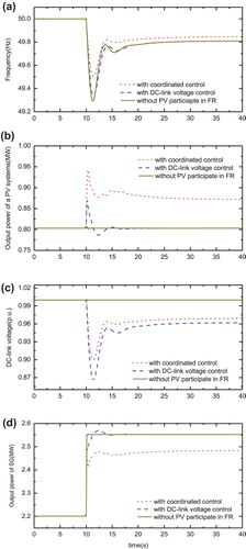
From (a), it is clearly seen that when only diesel generator assumes the frequency regulation responsibility, the frequency nadir is 49.290 Hz and the quasi-steady state frequency is 49.808 Hz. While the frequency nadir increases to 49.335 HZ, and the time that frequency reaches to its nadir is delayed with DC-link voltage control. This is because when load increases, the DC-link voltage decreases, which can be seen in (c). and then the extra power support is provided by PV systems, as shown in (b). This control method may avoid the action of replay protection system, as the rate of change of frequency slows down and dynamic frequency deviation, which denotes the different between frequency nadir and the nominal value, reduces. However, the DC-link capacitor absorbs a portion of energy during the period that its voltage recovers to a steady value. As a consequence, the output solar power exists a several seconds falling down after the power surge. When the deloading control is also introduced in, the frequency nadir reaches to 49.503 HZ and the steady state frequency increases to 49.846 HZ. From (b), it can be seen that the active power support that provided by the deloading control can not only offset the active power dip problem, but also afford a permanent frequency support. Hence the coordinated control strategy improves the frequency response of PV systems, and the frequency regulation burden of diesel generator is alleviated, as shown in (d).
When at 10 s, the load 2 is suddenly disconnected from the system. Performances of three similar scenarios are shown in .
Figure 7. Simulation results of the proposed frequency control when load decreases. (a) System frequency, (b) Output power of PV systems, (c) DC-link voltage, (d) Output power of diesel generator.
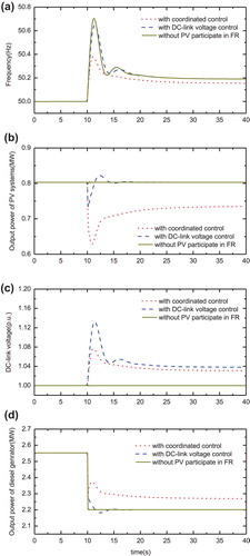
As seen in (a), when PV systems don’t participate in frequency regulation, the frequency peak is 50.704 HZ and the steady state frequency is 50.191 HZ. When the DC-link voltage control is implemented, the frequency peak decreases to 50.652 HZ, and the time that frequency reaches to its peak is also delayed. It is noted that, in this load sudden decrease situation, the reduction of dynamic frequency deviation is more significant than the same load increase situation, since the DC-link voltage rises and the DC-link capacitor absorbs more energy throughout the disturbance, as shown in (c). However, during the voltage recovery period, the DC-link capacitor releases energy and the output solar power increase problem still exists, as shown in (b). When the coordinated frequency control is applied, the frequency peak decreases to 59.380 HZ and the steady state frequency declines to 50.155 HZ. It is clear that the frequency peak diminution is also more significant compared with the frequency nadir improvement in load increase situation. This is because PV systems can continue deloading according to the droop control gain and the continue deloading level doesn’t limited by the predefined 10% reserve margin. The variation of output power of diesel generation is also reduced due to the contribution of the proposed coordinated frequency control strategy, as shown in (d). Based on above analysis, we can draw a conclusion that the frequency support offered by DC-link voltage control and deloading is more effective under-frequency increase situation.
5. Conclusion
This paper presents a coordinated control strategy that PV systems and the diesel generator act together to maintain frequency stability in an islanded microgrid. In order to mimic the inertia characteristic of synchronous generator, the energy stored in the DC-link capacitor is utilized. Dynamic simulation results show that it can provide a fast power support and reduce the dynamic frequency deviation. However, this extra power support is temporary, and the output solar power dip or rise problem during the voltage recovery period is non-ignorable. To solve this problem and provide a permanent frequency support, a 10% power margin of PV systems is reserved. Based on deloading, PV systems can participate in primary frequency control like conventional generators, which has a significant significance on mitigating the quasi-steady state frequency error. The coordinated control integrates merits of these two control strategies, and simulation results show that the dynamic frequency deviation and steady state frequency deviation have a remarkably reduction with the coordinated control no matter when load increase or decrease disturbance occurs.
Notes on contributors
 Xue Lyu
received her BS and MS degrees from Qingdao University of Technology, China, in 2013, and Shanghai University of Electric Power, China, in 2016 in Electrical Engineering, respectively. She is currently pursuing her PhD degree in The Hong Kong Polytechnic University. Her main research interest is grid integration of renewable energy.
Xue Lyu
received her BS and MS degrees from Qingdao University of Technology, China, in 2013, and Shanghai University of Electric Power, China, in 2016 in Electrical Engineering, respectively. She is currently pursuing her PhD degree in The Hong Kong Polytechnic University. Her main research interest is grid integration of renewable energy.
 Zhao Xu
received his PhD degree in electrical engineering from The University of Queensland, Brisbane, Australia, in 2006.From 2006 to 2009, he was an assistant and later associate professor with the Centre for Electric Technology, Technical University of Denmark, Lyngby, Denmark. He is now a professor with Hong Kong Polytechnic University. His research interests include demand side, grid integration of wind and solar power, electricity market planning and management, and AI applications. He is an editor of the Electric Power Components and Systems Journal and editor of IEEE Power Engineering Letter, IEEE Transactions on Smart Grid.
Zhao Xu
received his PhD degree in electrical engineering from The University of Queensland, Brisbane, Australia, in 2006.From 2006 to 2009, he was an assistant and later associate professor with the Centre for Electric Technology, Technical University of Denmark, Lyngby, Denmark. He is now a professor with Hong Kong Polytechnic University. His research interests include demand side, grid integration of wind and solar power, electricity market planning and management, and AI applications. He is an editor of the Electric Power Components and Systems Journal and editor of IEEE Power Engineering Letter, IEEE Transactions on Smart Grid.
 Jian Zhao
received his BEng. degree from Zhejiang University, Hangzhou, China, in 2013, and PhD degree in electrical engineering from Hong Kong Polytechnic University, Hong Kong, in 2017, where he is currently working as a research assistant. Zhao was a visiting scholar at Argonne National Laboratory, Argonne, IL, USA. He was a recipient of the 2016 IEEE PES Best Paper Reward. His research interests include distribution network operation and planning, grid integration of electric vehicles, and renewable energies.
Jian Zhao
received his BEng. degree from Zhejiang University, Hangzhou, China, in 2013, and PhD degree in electrical engineering from Hong Kong Polytechnic University, Hong Kong, in 2017, where he is currently working as a research assistant. Zhao was a visiting scholar at Argonne National Laboratory, Argonne, IL, USA. He was a recipient of the 2016 IEEE PES Best Paper Reward. His research interests include distribution network operation and planning, grid integration of electric vehicles, and renewable energies.
Disclosure statement
No potential conflict of interest was reported by the authors.
Funding
This is work was supported by the Hong Kong RGC Theme Based Research Scheme [grant number T23-407/13N] and [grant number T23-701/14N].
References
- Wan C, Xu Z, Pinson P. Direct interval forecast of wind power generation. IEEE Trans Power Syst. Nov 2013;28(4):4877–4878.
- Kabir MN, Mishra Y, Ledwich G, Xu Z, Bansal RC. Improving voltage profile of residential distribution systems using rooftop PVs and Battery Energy Storage systems. Appl Energy. Dec 2014;134:290–300.10.1016/j.apenergy.2014.08.042
- EON Netz GmbH. Grid code - high and extra high voltage. Bayreuth: E.ON Netz GmbH; April 2006.
- National Grid (Great Britain) Company. The grid code. London: National Grid (Great Britain) Company; 2006.
- Nordel. Nordic grid code 2007 (Nordic collection of rules), ed, 2007.
- Kayikci M, Milanovic JV. Dynamic contribution of doubly-based wind plants to system frequency disturbances. IEEE Trans Power Syst. Mar. 2009;24(2):859–867.10.1109/TPWRS.2009.2016062
- Gautam D, Goel L, Ayyanar R, et al. Control strategy to mitigate the impact of reduced inertia due to doubly fed induction generators on large power systems. IEEE Trans Power Syst. Feb. 2011;26(1):214–224.10.1109/TPWRS.2010.2051690
- Van de Vyver JV, De Kooning JDM, Meersman B, Vandevelde L, Vandoorn TL. Droop control as an alternative inertial response strategy for the synthetic inertia on wind turbines. IEEE Trans Power Syst. 2016;31:1129–1138.10.1109/TPWRS.2015.2417758
- Zhang ZS, Sun YZ, Lin J, et al. Coordinated frequency regulation by doubly fed induction generator-based wind power plants. IET Renewable Power Gener. Jan. 2012;6(1):38–47.10.1049/iet-rpg.2010.0208
- Zhao JJ, Lyu X, Fu Y, Hu XG. Coordinated microgrid frequency regulation based on DFIG variable coefficient using virtual inertia and primary frequency control. IEEE Trans Energy Convers. Sep.2016;31:833–845.10.1109/TEC.2016.2537539
- Uehara A, Pratap A, Goya T, Senjyu T, Yona A, Urasaki N, Funabashi T. A coordinated control method to smooth wind power fluctuations of a PMSG-Based WECS. IEEE Trans Energy Convers. Jun. 2011;26(2):550–558.10.1109/TEC.2011.2107912
- Arani MFM, El-Saadany EF. Implementing virtual inertia in DFIG-based wind power generation. IEEE Trans Power Syst. May 2013;28(2):1373–1384.
- Adhikari NS, Li F. Coordinated V-f and P-Q control of solar photovoltaic generators with MPPT and battery storage in microgrids. IEEE Trans Smart Grid. May 2014;5(3):1270–1281.
- Moutis P, Vassilakis A, Sampani A, Hatziargyriou ND. DC switch driven active power output control of photovoltaic inverters for the provision of frequency regulation. IEEE Trans Sustain. Energy. Oct. 2015;6(4):1485–1493.
- Li P, François B, Degobert P, Robyns B. Power control Strategy of a photovoltaic power plant for microgrid applications. Beijing, China: Proceedings of ISES World Congress; Sep. 2007. p. 1611–1616.
- Xin HH, Liu Y, Wang Z, Gan DQ, Yang TC. A new frequency regulation strategy for photovoltaic systems without energy storage. IEEE Trans Sustain Energy. Oct. 2013;4(4):985–993.
- Zarina PP, Mishra S, Sekhar PC. Exploring frequency control capability of a PV system in a hybrid PV-rotating machine-without storage system. Int J Elect Power Energy Syst. Sep.2014;60:258–267.10.1016/j.ijepes.2014.02.033