
 ?Mathematical formulae have been encoded as MathML and are displayed in this HTML version using MathJax in order to improve their display. Uncheck the box to turn MathJax off. This feature requires Javascript. Click on a formula to zoom.
ABSTRACT
This work proposes an auto-regressive (AR) model-based algorithm that can eliminate the adverse influence of the exponentially decaying DC offset in the phasor estimation process using discrete Fourier transform (DFT). The proposed algorithm comprises three stages: DFT, AR model implementation, and compensation. First, DFT can eliminate all harmonic components and estimate the phasor of the fundamental frequency component. Second, the AR model is used to calculate the error caused by the exponentially decaying DC offset in the phasor value estimated by DFT. A second-order AR model that uses three successively estimated phasor values is utilized. Finally, the phasor of the fundamental frequency component can be accurately estimated by compensating the error caused by the exponentially decaying DC offset. The performance of the proposed algorithm is evaluated for a-phase to ground fault on a 154 kV 25 km overhead transmission line. Electromagnetic Transients Program is used to generate fault signals. The evaluation result suggests that the proposed algorithm can effectively suppress the adverse influence of the DC offset.
1. Introduction
Discrete Fourier transform (DFT) is generally used to calculate the phasor of the fundamental frequency component in digital protective relays. However, the phasor value estimated by DFT contains an error caused by exponentially decaying DC offsets. For this reason, the DC offset component in a fault relaying signal adversely affects the accuracy and the operating speed of a digital protection relay. Therefore, the decaying DC component should be carefully considered in calculating the phasor of the fundamental frequency component of a relaying signal.
Several numerical techniques have been proposed to reduce or remove the adverse effect of the decaying DC offset component. In [Citation1], a DFT algorithm with a preconditioning digital mimic filter was proposed to suppress the decaying DC offset in a current waveform. The digital mimic filter can completely remove the decaying DC offset only when the actual time constant of a DC offset in a fault relaying current is the same as that of the mimic filter. A modified Fourier algorithm [Citation2] was proposed to remove the influence of the decaying DC offset on a fault relaying signal. This method can reduce the influence of but not completely remove the decaying DC offset. An AR model-based method was proposed in [Citation3] to remove the effect of the DC offset on a relaying signal. However, this method can remove the decaying DC offset only when a relaying signal consists of the fundamental frequency component and a decaying DC offset component. A DFT-based modified phasor estimation method was proposed in [Citation4]. The error due to the exponentially decaying DC offset on the DFT is calculated and eliminated using the outputs of the even- and odd-sample-set DFTs. However, this method is disadvantageous because the high-frequency noise components are amplified by the subtraction process of calculating the error caused by the DC offset.
We propose an AR model-based algorithm to eliminate the adverse influence of the exponentially decaying DC offset. The proposed AR model is implemented with phasor values estimated by the DFT to improve the disadvantage of the existing AR model in [Citation3], which is vulnerable to harmonics. The error due to the DC offset in the phasor value estimated by the DFT is calculated and eliminated using three successively estimated phasor values to accurately estimate the phasor of the fundamental frequency component. The performance of the proposed algorithm is evaluated for a-phase to ground (a–g) faults on a 154 kV 25 km overhead transmission line. Electromagnetic Transients Program (EMTP) was used to generate the fault relaying signals. The results of the proposed algorithm are compared to those of the conventional DFT and Modified DFT in [Citation2] to demonstrate its performance. Evaluation results indicate that the proposed algorithm can effectively eliminate the adverse influence of the DC offset.
2. Propsed algorithm
2.1. Auto-regressive model
In an AR model, series data can be described by past values and expressed as follows:
This model is a second-order AR model because the value at time (k) is predicted from the values at times (k-1) and (k-2). A p-th-order AR model is generally a multiple linear regression in which the value of the series at any time (k) is a weighted sum of the values until the time (k-p) passes; it can be expressed as follows:
2.2. Error caused by exponentially decaying DC offset in phasor value estimated by DFT
When a fault occurs in a power system, the current signal can be generally considered the combination of an exponentially decaying DC offset and sinusoidal components. If sinusoidal components with frequencies higher than the (N/2–1) order are assumed to be eliminated by an anti-aliasing low-pass filter, the current signal can be expressed as follows:
where and
are the magnitude and the time constant of an exponential component, respectively;
and
are the amplitude and the phase angle of the n-th harmonic component, respectively;
is the sampling interval; and
is the number of samples per cycle.
The phasor of the fundamental frequency component is calculated by the DFT as follows:
where and
are the imaginary and real parts of the fundamental frequency phasor, respectively.
The estimated phasor value by Equation (4) is as follows:
where
As shown in Equations (5) and (6), the estimated phasor value contains an error that is caused by the exponentially decaying DC offset in addition to the fundamental frequency component. This equation can be rewritten as follows:
where
Therefore, to obtain the accurate fundamental frequency component, the error caused by the DC offset included in the estimated phasor value must be eliminated.
2.3. AR model for fundamental frequency component
The second derivative of the imaginary part of the fundamental frequency component can be calculated using a central difference approximation formula of Equation (9).
The second derivative term can be expressed as follows:
Substituting Equation (10) into the left side of Equation (9) obtains the following:
From Equation (11), the imaginary part of the fundamental frequency component can be represented by the following second AR model:
Similarly, the real part of the fundamental frequency component can be represented by the following second AR model;
2.4. Calculation of error caused by exponentially decaying DC offset in estimated phasor value
The imaginary part of the estimated phasor value can be expressed with the error caused by the exponentially decaying DC offset as shown in Equation (14).
The pure fundamental frequency component from the estimated phasor value should be eliminated to estimate the error caused by the exponentially decaying DC offset in the estimated phasor value.
From Equations (12) and (14), the following equation can be obtained:
Equation (15) can be rewritten with the following equation consisting only of the error caused by the exponentially decaying DC offset.
From Equation (16), the error due to the exponentially decaying DC offset in the estimated phasor value can be expressed as follows:
From Equation (17), the error due to the exponentially decaying DC offset in the calculated phasor value can be calculated by and
, where
can be calculated by three imaginary parts of DFT, as shown in Equation (16), and
can be calculated by the constants (
,
) and unknown variable (
). The time constant of the DC offset is required to calculate
given that the time constant (
) is an unknown variable. From Equation (16), the following equation can be obtained:
The error due to the exponentially decaying DC offset in the imaginary part of the estimated phasor value can be calculated in Equation (17) using the calculated time constant.
Similarly, the error due to the exponentially decaying DC offset in the real part of the estimated phasor value can be calculated by Equation (19).
can be calculated by three real parts of the estimated phasor value, and
can be calculated from the constants (
,
) and unknown variable (τ). Then,
can be calculated because the time constant of the DC offset is already obtained by Equation (18). Therefore, the error due to the exponentially decaying DC offset in the real part of the estimated phasor value can be calculated by Equation (19).
2.5. Compensation of error caused by exponentially decaying DC offset in estimated phasor value
The phasor of the fundamental frequency component can be accurately estimated by subtracting the error caused by the exponentially decaying DC offset calculated from Equations (17) and (19) from the estimated phasor value.
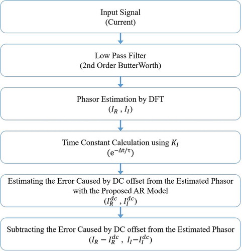
shows the flowchart of the proposed algorithm. A low-pass filter is used for anti-aliasing, and the DFT can eliminate all harmonic components and estimate the phasor of the fundamental frequency component. The time constant of the DC offset is calculated using KI, and the error due to the exponentially decaying DC offset in the estimated phasor value is calculated using the AR model that reflects the calculated time constant. Finally, the phasor of the fundamental frequency component can be accurately estimated by compensating the error caused by the exponentially decaying DC offset.
Figure 1. Flowchart of proposed algorithm.
3. Performance evaluation
3.1. System configuration
In this section, the performance evaluation of the proposed algorithm is described. The current signals are generated by EMTP. The model system for the simulations is a 154 kV 25 km overhead transmission with sources at both ends, as shown in . The transmission line parameters used in the simulation are presented in .
Table 1. Overhead transmission line parameters.
Figure 2. Single-line diagram of model system.
The time constant and magnitude of the decaying DC offset vary depending on the system configuration and fault conditions, such as the fault location, resistance, and inception angle. The time constant of the DC offset is generally determined by the fault resistance and the impedance ratio (X/R) of the system. As shown in , different source impedances are used for Cases 1 and 2 to consider the effect of the source impedance ratio on the time constant. A fault inception angle of 0° is considered for the maximum magnitude of the DC component.
Table 2. Equivalent source parameters.
3.2. Case studies
- show the estimated RMS values of the fault currents. At this time, the effect of the fault distance is considered. The time constant of the DC offset is changed by the fault distance from the relaying point. For comparison, the results obtained with the conventional DFT and Modified DFT are also shown in each figure.
Figure 3. Test results according to change in fault distance (fault distance: 10 [%], source impedance ratio: case 1).
![Figure 3. Test results according to change in fault distance (fault distance: 10 [%], source impedance ratio: case 1).](/cms/asset/61b7c960-b21b-44ef-9c88-c4e4f0ab6d03/tjee_a_1515692_f0003_oc.jpg)
Figure 4. Test results according to change in fault distance (fault distance: 50 [%], source impedance ratio: case 1).
![Figure 4. Test results according to change in fault distance (fault distance: 50 [%], source impedance ratio: case 1).](/cms/asset/299f827e-818b-48a5-8858-799745911ff3/tjee_a_1515692_f0004_oc.jpg)
Figure 5. Test results according to change in fault distance (fault distance: 90 [%], source impedance ratio: case 1).
![Figure 5. Test results according to change in fault distance (fault distance: 90 [%], source impedance ratio: case 1).](/cms/asset/5aed67c6-43e5-421e-b71c-e80a7917cf1f/tjee_a_1515692_f0005_oc.jpg)
shows the test results for a solid a-phase to ground fault at 10[%] of the total line length from the relaying point. For a solid fault, the fault current flowing through a power line contains the exponentially decaying DC offset which depends on the local source impedance, the line impedance, and the impedance of the ground. Compared to the other algorithms, the result of the conventional DFT shows not only the largest transient overshoot but also the largest oscillatory response. ) shows only the proposed algorithm and the Modified DFT for accurate comparison. As shown in ), the proposed algorithm can more accurately remove the adverse influence of the DC offset than the Modified DFT.
and show the test results for a solid a-phase to ground fault at 50[%] and 90[%] of the total line length from the relaying point, respectively. As shown in and (), the result of the conventional DFT shows not only the largest transient overshoot but also the largest oscillatory response. and () shows only the proposed algorithm and the Modified DFT for accurate comparison. As shown in and , the proposed algorithm can more accurately remove the adverse influence of the DC offset than the Modified DFT.
and show the test results for a solid a-phase to ground fault at 0.1 km from the relaying point. At this time, the effect of the source impedance is considered. The time constant of the DC offset is changed by the X/R of the local source impedance. As shown in and , the result of the conventional DFT shows not only the largest transient overshoot but also the largest oscillatory response. and shows only the proposed algorithm and the Modified DFT. As shown in and , the proposed algorithm can more accurately remove the adverse influence of the DC offset than the Modified DFT.
Figure 6. Test results according to change of the source impedance ratio (fault distance: 0.1 [km], source impedance ratio: case 1).
![Figure 6. Test results according to change of the source impedance ratio (fault distance: 0.1 [km], source impedance ratio: case 1).](/cms/asset/8566cc08-6fdf-45b1-a63c-b9cb31b633e8/tjee_a_1515692_f0006_oc.jpg)
Figure 7. Test results according to change of the source impedance ratio (fault distance: 0.1 [km], source impedance ratio: case 2).
![Figure 7. Test results according to change of the source impedance ratio (fault distance: 0.1 [km], source impedance ratio: case 2).](/cms/asset/ba8fbe56-8ea7-43f9-b543-de1b2de90567/tjee_a_1515692_f0007_oc.jpg)
4. Conclusions
An algorithm based on a proposed AR model is proposed to eliminate the adverse influence of exponentially decaying DC offset. The error due to the DC offset in the phasor value obtained from DFT is calculated and eliminated with the AR model. The performance results show that the proposed algorithm is not affected by the system and the fault conditions. The output of the proposed algorithm is stable and does not have oscillatory response, unlike that of the other algorithms. Thus, the proposed algorithm can effectively suppress the adverse influence of the DC offset in a relaying signal.
Disclosure statement
No potential conflict of interest was reported by the authors.
Additional information
Funding
Notes on contributors
Woo-Joong Kim
Woo-Joong Kim: He received his B.S. and M.S. degrees from Myongji University, Korea, in 2012 and 2014, respectively. He is now studying for his Ph.D. degree at Myongji University. He has been with Next-generation Power Technology Center, Korea, since 2012. His main research interest is power system protection.
Sang-Hee Kang
Sang-Hee Kang: He is a professor at Myongji University, Korea. He received the B.S., M.S. and Ph.D. degrees from Seoul National University, Korea in 1985, 1987 and 1993, respectively. He was a visiting fellow and a visiting scholar at the University of Bath, UK in 1991 and 1999. His research interest is to develop digital protection systems for power systems using digital signal processing techniques.
References
- Benmouyal G. Removal of DC offset in current waveforms using digital mimic filtering. IEEE Trans Power Delivery. 1995 Apr;10(2):621–630.
- Nam S-R, Kang S-H, Park J-K. An analytic method for measuring accurate fundamental frequency components. IEEE Trans Power Delivery. 2002 Apr;17(2):405–411.
- Chang S-Y, Lee D-G, Kang S-H. AR model and LSQ based compensation method for the saturated secondary current of a current transformer. Trans KIEE. 2006 Jun;55A(6):221–226.
- Kang S-H, Lee D-G, Nam S-R, et al. Fourier transform-based modified phasor estimation method immune to the effect of the DC offsets. IEEE Trans Power Delivery. 2009 Jul;24(3):1104–1111.