
 ?Mathematical formulae have been encoded as MathML and are displayed in this HTML version using MathJax in order to improve their display. Uncheck the box to turn MathJax off. This feature requires Javascript. Click on a formula to zoom.
ABSTRACT
Codebook design is a key point in beam-forming which is necessary for millimetre Wave (mmWave) communication to compensate its huge free space path loss. In beam-forming codebook, the transmitter and the receiver co-operate to select the optimum pre-designed code vectors to satisfy robust, efficient, and reliable transmission link between two pairs. In our study, we propose a new codebook structure based on unique phase states. Based on the Array Factor (AF) and Signal-to-Noise Ratio (SNR), the proposed codebook is compared and evaluated with the uniform weighting codebook, circular array codebook, and IEEE 802.15.3c standard codebook. The results show that the proposed codebook achieves comparable SNR and array directivity with the IEEE 802.15.3c, but higher peak and wide dynamic range of SNR and better array directivity compared with the uniform weighting and circular antenna codebooks. Thus, the proposed codebook is expected to improve signal quality and increase user throughput significantly.
Introduction
Due to rapid growth demand for wideband data transmission, mmWave communication band is getting significant attention in wireless-local area networks (W-LANs) and wireless-personal area networks (W-PANs). mmWave communication band is short range high data rate communication system with huge unlicensed bandwidth, high capacity, and flexibility. Also, it allows high transmit power and less interference effect. Moreover, it is applied in large file transfer and uncompressed high-definition video streaming [Citation1]. Further improving transmission range of mmWave band also enhances spatial efficiency [Citation2,Citation3].
However, the mmWave band faces many impairments such as high free space path loss level, high attenuation, and oxygen absorption compared with low-frequency communication band [Citation1,Citation3]. Interstingly, to compensate the significant path loss in mmWave comunication, the directional antennas are used to generate narrow directional beams to provide the important gain [Citation4,Citation5].
Beam-forming techniques help to investigate many benefits including the system throughput enhancement, spatial reuse, and minimal interference. Moreover, as the antenna size is directly proportional to wavelength, the mmWave antenna is tiny compared with another low-frequency communication. Therefore, the beam-forming technology can be used to improve the link quality as well as angle information distribution. All these factors motivate the researchers to focus on mmWave communication [Citation4,Citation5]. The analog beam-forming is much less hardware complexity and power consumption constraint so that it is preferred in 60 GHz indoor mmWave communication [Citation2,Citation5]. The main purpose of the array antenna is to improve the SNR by adding correlated signals and uncorrelated noise[Citation6]. This improvement is measured in terms of array gain or array response [Citation7]. The mmWave communication uses two techniques. The first is codebook based beam steering to solve energy constraint. The second one has phased array antennas with fixed amplitude beam weighting vector to solve complexity problem. In phased array antenna, the beam pattern is generated by shifting each antenna element RF signal [Citation8]. Moreover, the codebook is referred in several ways to set antenna weight coefficients. Training is referred to the way of finding the best beam pair between transmitter and receiver [Citation9]. Taking IEEE 802.15.3c as a reference codebook, there are many studies conducted in different ways to construct codebooks. In [Citation9], uniform weighting based codebook is constructed by simple weighting window function and a weighting vector constituting a conjugate number. The circular codebook weights vector is constructed by circularly shifting each column [Citation1]. In this paper, we propose a new form of codebook design based on the number of phase states. Additionally, the proposed codebook is compared with the reference codebooks using SNR and AF as performance evaluation factors.
MIMO system model
The MIMO system model is shown in . The device 1 (DEV1) is equipped with a linear array of transmit antennas, the device 2 (DEV2) has
received antenna element. Data transmission between the two devices involves the following: at the transmitter side, the baseband signal is up-converted to RF band, then the signal is multiplied by the transmitter code vector
.
Figure 1. Schematic diagram of MIMO system model.
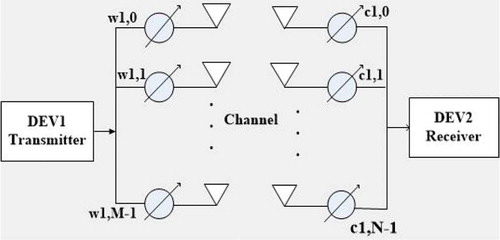
On the receiver side, the received RF signal is down-converted to a baseband signal, and then multiplied by the receiver code vector ; both the transmitter and receiver weight vectors satisfy
. The beams are generated by shifting each antenna element RF signal, and each column (beam) is circularly generated by shifting a previous beam by angle
[Citation1,Citation10].
Codebook design and principles
The followings are four principles of codebook design [Citation11]: First, the codebook designed for the phased antenna, each column of codebook matrix determine the phase shift of each element. Second, the IEEE 802.15.3c codebook constructed with phase resolution without changing in amplitude[Citation12]. Third, codebooks support different antenna configurations and available for multi-antenna elements. Fourth, the columns in the codebook are orthogonal. Therefore multiple beams can be generated simultaneously with minimum interference [Citation3,Citation9].
Ieee802.15.3c codebook design
Let’s consider a linear array antenna with uniform spacing of half wavelength, the system with antenna elements and
is the required beam patterns generated by the codebook, then when
, each element of the codebook matrix is given by:
The function returns the biggest integer, which is smaller or equal to its value. The expression in (1) is called IEEE 802.15.3c codebook with four discrete phases [Citation9]. From (1) we can express N-phase’s codebook as follow:
where is used to indicate the number of discrete phases.
Uniform weighting based codebook
Uniform weighting is a simple window weighting function scheme; the weights are selected to generate beam patterns in directions according to the direction of main response axis (MRA) . When the MRA is in the direction of , where
is the direction of
beam, and if the normal line is
array antenna, and the uniform antenna element spacing is
, then the codebook weight elements are given by:
Proposed codebook
The discrete resolution codebook, for
antenna elements of the uniform phase array, is similar as described in (1), this codebook matrix each column is corresponding to the phase rotation of antenna elements. The
resolution codebook in (1) generates patterns with un-equal gain along the central axis because the quantization of phase is limited by
resolution, it is clear that the beam patterns generated by (1) as mentioned in [Citation9] have an unequal gain. We propose a different codebook weighting element construction, compared with other reviewed codebooks, the main difference is the phase state which follows
, where
is integer positive number. The expression of the entire codebook weighting elements is given as:
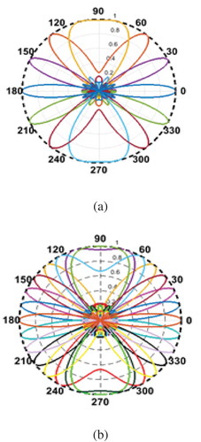
The codebook as expressed in (4) is reasonable to improve the phase resolution and achieves equal gain along the main response axis. explains the beam pattern generated by proposed codebook in (4).
Figure 2. Proposed codebook beam patterns: (a) ; (b)
.
The codebooks in (1), (3), and (4) are considered as a uniform spacing linear array antenna. Therefore AF can be written as (5):
The weight vector in a given beam direction in the matrix form is given by , where
is the polar angle of the direction of arrival (DOA) with respect to the reference axis,
is the spacing between elements;
,
, and
are; signal wavelength, required beam patterns, and the number of antenna elements respectively [Citation4].
Similarly, we can obtain array factor and codebook weight vector from corresponding
array factor and codebook in a given direction. We assume that the antenna elements are located in
plane, the polar angle with respect to
is
, the azimuth angle with respect to
is
,
and
are the spacing between elements in both direction,
and
are the number of antenna elements in the direction of
and
respectively, the
AF is the result of AF in
direction multiplied by AF in
direction to give
array factor as follow:
, by using the summation consecutively of two
AF to obtain the
array factor as follow[Citation11]:
Circular antenna codebook design
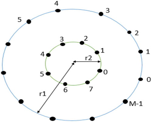
Suppose the circular array antenna consists of two layers as shown in , the outer circle with radius , where
is the number of antenna elements in multiple of 8. The inner circle radius is
, more information about inner and outer layers can be found in reference [Citation1]. In this paper, we focus on the outer circle to design the codebook of circular array antenna which is used mainly to produce the beam patterns, then the weight vector for this codebook is written as:
Figure 3. Two-layer circular array antenna model.
Antenna array response of circular codebook is given by:
Similarly, array response is expressed as follow:
Equation (9) can be rewritten as:
The maximum value of AF occurs when all phases are equal to unity or
where ; the principle of maximum pattern direction when
is defined by
, where
and
.
SNR expression
At the beginning of transmission, the RF signal weighted at DEV1, and by applying weighting vector
at the transmitter side, the
signal vector will be produced and transmitted. The transmitted signal will be received by DEV2, by applying receiver weight vector
, which is predefined code vector at the receiver side, the combined received signal and noise in [Citation13] is written as:
where is conjugate transpose matrix of DEV2 codebook matrix
,
is
channel matrix which is constructed as in [Citation14],
is
transmitted signal and
is
additive white Gaussian noise with variance
. The total power of all transmit antennas is normalized by
as:
The weight vector follows the relation: and
, from (11) the output SNR can be derived as:
Furthermore, from (12) the expression in (13) can be rewritten as:
Expression (14) explains the received SNR.
Results and discussion
In this section, we evaluate the performance of the proposed codebook with the reference codebooks through simulation.
SNR evaluation
The results are obtained by selecting the number of beams and the SNR calculated at different noise variances
.
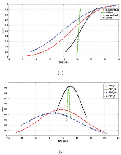
From ), taking the noise variance , for codebook indices from 12 to 18, the IEEE802.3c and the proposed codebooks achieve much higher SNR than uniform and circular codebooks by 14dB and 8dB respectively. However, for codebook indices from 1 to 3 and from 30 to 32, the proposed codebook achieves much higher SNR than IEEE802.3c by about 20dB. The main reason behind these variations is the geometric arrangement of the weight elements, which mainly depend on the steering weighting function of each codebook.
Figure 4. SNR of codebooks vs beam index (K): (a) ; (b)
.
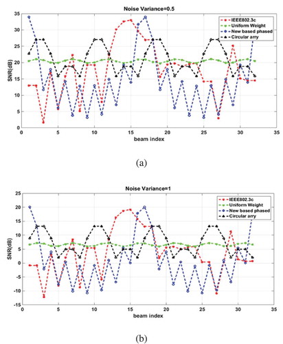
By taking , as shown in ), the comparison trends look the same as in ) when
. However, the effect of noise dramatically degrades the absolute value of SNR for all codebooks by about 15dB, it is verified in equation (14) in which more noise is gained by the number of receive antenna elements
. The results show that the proposed codebook has a higher peak and dynamic range than the reference codebooks.
In , the CDF and PDF of SNR are obtained, it is observed from ) the SNR distribution of the uniform codebook is very narrow compared with the other three codebooks because the uniform codebook has a small dynamic range. On the other hand, the probability of CDF of the proposed codebook has a higher value than other codebooks with higher dynamic range. From ), the proposed codebook and the IEEE802.3c have wide SNR and comparable PDF values, unlike the uniform and circular codebooks which have narrow SNR values.
Figure 5. CDF and PDF distributions for SNR of codebooks: (a) ; (b)
.
Array factor evaluation
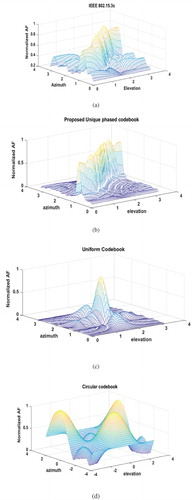
In this paper, we compute AF as a function of angles to get the
plot as shown in . The Elevation and azimuth angles are considered for linear array antenna in the range
, and for circular array antenna in the range
. By increasing arbitrarily selected step angle
, i.e.
the proposed and IEEE802.15.3c codebooks have maximum array responses approximately at angle pairs from
to
as shown in and 6(b). However, IEEE802.15.3c has more peak sidelobes than the proposed codebook. In ) the uniform codebook has maximum AF at
with small side lobes at
and
. From ), the circular codebook has maximum values at
and
with small minor side lobes. Thus, regarding coverage, the circular codebook is desirable. On the other hand, in terms of the ratio of peak to minor side lobes the proposed codebook is the choice. However, the ratio of peak to minor side lobes criterion is given more emphasis than the coverage in mmWave communication. Hence, the proposed codebook is preferably better than others.
Figure 6. Three dimension codebooks array response (a) IEEE802.3c codebook; (b) Proposed codebook; (c) Uniform codebook; (d) Circular codebook.
Conclusion
In this paper, a new codebook is proposed and compared with the IEEE 802.15.3c, uniform weighting, and circular antenna codebooks. The results show that the proposed codebook achieves comparable SNR and array directivity with the IEEE 802.15.3c, but higher peak and wider dynamic range of SNR and better array directivity compared with the uniform weighting and circular antenna codebooks. Thus, the proposed codebook is expected to improve signal quality and increase user throughput significantly.
Acknowledgments
This work is supported by National Key Laboratory of Electromagnetic Environment, China Research Institute of Radiowave Propagation under grant No. JW2016-014.
Disclosure statement
No potential conflict of interest was reported by the authors.
Additional information
Funding
Notes on contributors

Adam Mohamed Ahmed Abdo
Adam Mohamed Ahmed Abdo was born at North Darfur, Sudan. He was admitted as a PhD student at North China Electric Power University in 2015. He received his bachelor and master degrees at School of Electronic Engineering, Sudan University of Science & Technology in 2007 and 2014 respectively. From Jan. 2014 to Sep. 2015, he was Senior Lecturer at Faculty of Engineering Science, Electrical and Electronic Department, University of Nyala, Sudan. His main field of interest is 5G in millimeter wave communications. Email: [email protected]

Xiongwen Zhao
Xiongwen Zhao (SM’06) received his Ph.D. degree in 2002 with high honors from Helsinki University of Technology (TKK), Finland. From July 1992 to Sept. 1998, he was with the Laboratory of Communications System Engineering at China Research Institute of Radiowave Propagation, where he was a Director and a Senior Engineer. From Oct. 1999 to Sept. 2004, he was with the Radio Laboratory, TKK, as s Senior Researcher and a Project Manager in the areas of MIMO channel modeling and measurements at 2, 5, and 60GHz as well as UWB. From Oct. 2004 to Dec. 2011, he was with Elektrobit Corporation (EB), Espoo, Finland, as a Senior Specialist at EB Wireless Solutions. During Oct. 2004 - June 2007, he worked in European WINNER project as a Senior Researcher in MIMO channel modeling for 4G radio systems. From 2006 to 2008, he also worked in the field of wireless network technologies such as WiMAX and wireless mesh networks (WMNs). From Nov. 2008 to Dec. 2009, he worked in satellite mobile communications for GMR-1 3G, DVB-SH RF link budget and antenna performance evaluations. During 2010 - 2011, he worked in the spectrum sharing and interference management between satellite and terrestrial LTE networks. He is now a Professor in wireless communications at North China Electric Power University in Beijing and chairs several projects by the National Science foundation of China (NSFC), the State Key Laboratories and Industries on channel measurements, modeling and simulations. He is a reviewer of IEEE Transactions, Journals, Letters, and Conferences. He was a recipient of IEEE Vehicular Technology Society (VTS) Neal Shepherd Best Propagation Paper Award in 2014. He has served as the TPC Members, Session Chairs, and a keynote speaker for numerous international and national Conferences. He is a Senior Member of IEEE. Email: [email protected]

Abdinasir Ahmed
Abdinasir Ahmed He is from Somalia, he got MSc and BSc from north china electric power university, major smart grid communication. Currently he is pursing toward Ph.D. at north china electric power university, Beijing, China. His field of interest is smart meter and power line communication. Email: [email protected]
References
- Feng W, Xiao Z, Jin D, et al. Circular-antenna-array-based codebook design and training method for 60GHz beamforming. IEEE Wirel Commun Netw Conf WCNC. 2013;4140–4145.
- Wang J, Lan Z, Pyo C-W, et al. Beam codebook based beamforming protocol for multi-Gbps millimeter-wave WPAN systems. IEEE J Sel Areas Commun. 2009;27(8):1390–1399.
- Xiao Z, He T, Xia P, et al. Hierarchical Codebook Design for Beamforming Training in Millimeter-Wave Communication. IEEE Transactions on Wireless Communications. vol. 15, pp. 3380-3392; 2016.
- Kutty S, Sen D. An improved numerical optimization method for efficient beam search in 60 GHz indoor millimeter wave wireless networks. Int Symp Adv Networks Telecommun Syst ANTS. 2016;2016–Febru:1–6.
- Lee HH, Ko YC. Low complexity codebook-based beamforming for MIMO-OFDM systems in millimeter-wave WPAN. IEEE Transactions on Wireless Communications. vol. 10, pp. 3607-3612: 2011
- Zou W, Wang L, Guo C. 3D-beamforming codebook design based on directly search for millimeter-wave communications. Proc. - IEEE INFOCOM. 2016;2016–Septe:1003–1008.
- Van Trees HL. Optimum array processing part IV of detection, estimation, and modulation theory. 2002.
- Alamri N, Akkari N. Umts-wimax vertical handover in next generation wireless networks: https://arxiv.org/ftp/arxiv/papers/1201/1201.1038.pdf.
- Zou W, Cui Z, Li B, et al. Beamforming codebook design and performance evaluation for 60GHz wireless communication. 11th Int. Symp. Commun. Inf. Technol. Isc. 2011, no. Iscit, pp. 30–35; 2011.
- Hosoya K, Prasad N, Ramachandran K, et al. Multiple sector ID capture (MIDC): A novel beamforming technique for 60-GHz band multi-Gbps WLAN/PAN systems. IEEE Trans Antennas Propag. 2015;63(1):81–86.
- W. Zou, Z. Cui, B. Li, Z. Zhou, and Y. Hu, “Beamforming codebook design and performance evaluation for 60GHz wireless communication,„ in 2011 11th International Symposium on Communications & Information Technologies (ISCIT), 2011, pp. 30-35.
- Zou W, Du G, Li B, et al. A unified codebook for fast beam searching in millimeter-wave communications. Int. Conf. Comput. Probl. ICCP 2012, no. 61171104, pp. 218–223, 2012.
- Zou W, Cui Z, Li B, et al. Beamforming codebook design and performance evaluation for 60GHz wireless communication.11th International Symposium on Communications & Information Technologies (ISCIT), pp. 30-35; 2011.
- He T, Xiao Z. Suboptimal beam search algorithm and codebook design for millimeter-wave communications. Mob. Networks Appl. 2015;20(1):86–97.