 ?Mathematical formulae have been encoded as MathML and are displayed in this HTML version using MathJax in order to improve their display. Uncheck the box to turn MathJax off. This feature requires Javascript. Click on a formula to zoom.
Abstract
In this paper, we propose a Space Fractional Reaction-Diffusion model for growth of corals in a tank. We analyse spatial temporal pattern formation behavior of the model through Turing type instability analysis. We determine the parameter regions of the model, in which the Turing instability occurs (the Turing instability space). We then discuss the effects of the fractional order and the model parameters on the spatial temporal patterns of the model. We investigate numerical solutions of the model using the Fourier Spectral method, two Euler type schemes and the MATLAB functionODE15s. The main advantage of using the Fourier spectral method is ability to represent the space fractional operator in fully diagonal form and ability to extend straightforwardly to two and three spatial dimensions. To find the numerical solutions with the other three methods, we transform the model equations into a system of ODEs by applying Matrix Transfer Technique and solve those system of ODEs. We compare the numerical solutions obtained by these methods and efficiencies of these methods.
Public Interest Statement
Modelling coral morphogenesis processes has become a significant area of research. In this research paper we propose a mathematical model for pattern formation in coral reefs, applying physical phenomena called fractional diffusion. The phenomena fractional diffusion is applied instead of standard diffusion, as it is more suitable to model complex processes like pattern formation in coral reefs. We analytically proved that solutions of the proposed model form spatial temporal patterns when model parameters satisfy specific conditions. Under the same conditions, we solved the model and observed that these numerical solutions form branching structures like branching corals. We discussed the effects of the model parameters and the fractional exponent on the pattern formation behaviour.
1. Introduction
The purpose of this investigation is to explore the suitability of space fractional diffusion phenomena in modelling coral reefs pattern formations. Fractional diffusion equations arise when modelling anomalous (deviations from normal) diffusions features that are observed in many systems (Li & Wang, Citation2003; Metzler & Klafter, Citation2000; Santoro, de Paula, Lenzi, & Evangelista, Citation2011; Sun, Chen, & Chen, Citation2009; Upadhyaya, Rieu, Glazier, & Sawada, Citation2001). This introductory section provides brief overviews of corals, coral modelling and fractional reaction diffusion models.
Coral reefs are formed by calcium carbonate skeletons. Reef skeletons are built by tiny coral animals called polyps by depositing dissolved calcium carbonate ions on the existing reef surface that make up large coral colonies. The morphogenesis of coral is complex and that complexity define the beauty of the coral world. Various modeling approaches on coral morphogenesis processes have been proposed (Kaandorp, Blom et al., Citation2008; Kaandorp, Lowe, Frenkel, & Sloot, Citation1996; Kaandorp, Sloot et al., Citation2005; Merks, Citation2003a,Citation2003b; Merks, Hoekstra, Kaandorp, & Sloot, Citation2003a,Citation2003b; Mistr & Bercovici, Citation2003). A reaction diffusion type mathematical model for growth of corals in a tank has been proposed by Somathilake and Janak (Citation2012,Citation2014) based on the model that considers the nutrient polyps interaction (Mistr & Bercovici, Citation2003). In this paper, we propose a new Fractional-Reaction-Diffusion model that reduces to the Reaction-Diffusion model presented in Somathilake and Wedagedera (Citation2014). Then we investigate the spatial temporal pattern formation behaviour of the proposed model.
Fractional calculus originated with the idea of a fractional derivative first raised by G. F. A. De L’Hôpital (1661–1704). However, in the past few decades Mathematicians have paid attention on fractional calculus and considerable developments have occured. In recent years there has been an increasing interest in fractional reaction diffusion equations in diverse and widespread fields of science and engineering (Benchohra, Henderson, Ntouyas, & Ouahab, Citation2008; Diethelm & Freed, Citation1999; Hilfer, Citation2000; Liu, Yang, & Turner, Citation2011; Sabatier, Agrawal, & Machado, Citation2007; Schiessel, Metzler, Blumen, & Nonnenmacher, Citation1995). Fractional reaction diffusion equations arise when modelling processes with non-locality and spatial heterogeneity. Especially, space fractional reaction diffusion models arise when modelling reaction and diffusion processes in heterogeneous media. Some analytical (Henry, Langlands, & Wearne, Citation2005; Jafari et al., Citation2013; Kirane, Ahmad, Alsaedi, & Al-Yami, Citation2014) and numerical (Bhrawy, Baleanu, & Mallawi, Citation2015; Bueno-Orovio, Kay, & Burrage, Citation2014; Bueno-Orovio & Pérez-Garca, Citation2006; Burrage, Hale, & Kay, Citation2012; Ilić, Liu, Turner, & Anh, Citation2005,Citation2006; Pindza & Owolabi, Citation2016; Rida, El-Sayed, & Arafa, Citation2010; Tchier, Inc, Korpinar, & Baleanu, Citation2016; Yang, Liu, & Turner, Citation2010; Yu, Liu, Anh, & Turner, Citation2008; Zhuang, Liu, Anh, & Turner, Citation2009) techniques play an important role in identifying the solution behaviour and obtaining approximate solutions of fractional differential equations.
The general form of the one variable fractional reaction diffusion equation is:(1)
(1)
Here ,
and
represent a fractional diffusion process, diffusion rate and the reaction process, respectively.
For , anomalous diffusion reduces to normal diffusion. For
, the diffusion process is slower (faster) than normal diffusion, where it is called sub-diffusive (super-diffusive). Sub-diffusion terms arise when we model processes related to spatial or temporal constraints such as fractured and porous media and fractal lattices (Henry & Wearne, Citation2000). Super-diffusion terms may arise when we model processes such as particles transportation through chaotic or turbulent media (Henry & Wearne, Citation2000). Coral reef mass can be considered as a porous medium. Therefore, in order to make the model more realistic, anomalous diffusion is considered in the model formation process.
In order to allow spatial temporal patterns to form by the solutions of a reaction diffusion system, the solutions should be stable in the absence of the diffusion, and be unstable in the presence of the diffusion (Murray, Citation2003; Turing, Citation1952). Similar arguments have been used in space fractional reaction diffusions equations (Henry et al., Citation2005; Tian, Zhou, & Deng, Citation2015). In this paper we perform a Turing type instability analysis of the proposed fractional reaction diffusion model and we determine instability regions (parameter ranges in which Turing instability occurs). Then we investigate effects of the fractional exponent on the pattern formation behaviour.
This paper is organized as follows. An explanation on the derivation of the mathematical model is given in Section 2. Turing type instability analysis of the model is performed in Section 3. Also, in the same section, we discuss the effects of the fractional exponent of the spatial diffusion and model parameters on spatial pattern formation by the solutions of the model. Some numerical methods based on finite difference and Fourier spectral methods are explained in Section 4. In Section 5, numerical results on 1D and 2D spaces are presented. Finally, we present the discussion and conclusions based on the results in Section 6.
2. Mathematical model
In this section we derive a Fractional-Reaction-Diffusion model for growth of coral in a tank. Consider a water filled tank with some coral larva (planula) settled on the bottom of the tank. Assume that the coral growth is taking place in this tank, and there is no fluid motion within the tank. Also, assume that coral polyps consume dissolved nutrients and produce additional solid material (corals produce their skeleton by extracting dissolved calcium carbonate surrounding them). This process can be regarded as a reaction process between dissolved nutrient and dissolved calcium carbonate (Mistr & Bercovici, Citation2003). Let A and B denote the dissolved nutrients and dissolved solid material (calcium carbonate), respectively, and u and v denote their respective biomasses. In this case, nutrient and solid material concentrations at a point is controlled by two processes, reaction and anomalous diffusion.
Thus, nutrients react with the dissolved solid material (calcium carbonate ions) and produce additional solid material. Assume that the reaction process of A and B takes the form (as in Mistr & Bercovici, Citation2003):
Assume that nutrients are supplied to the system in a constant rate and portion of the nutrients waste proportional to its instantaneous concentration. Then we can describe the time evolution process of nutrients as follows:
Assume that constant rates of nutrients supplying, wasting and reaction are a, b, and respectively. Let
and
be the diffusion rates of dissolved nutrient and calcium carbonate respectively. Then we can directly write the rate equation for the above process as:
(2)
(2)
This system can be written in the form:(3)
(3)
where . That is
is the overall nutrient supply rate to the system.
It is reasonable to assume that the time rate change of the dissolved solid material concentration is controlled by fractional diffusion, reactive production and loss due to aggregation on existing coral reefs. This process can be represented in the form:
which gives(4)
(4)
where is the depositing rate of calcium carbonate on the existing corals.
Let w denotes the depositing calcium carbonate concentration on the coral reef. This process can be represented by the equation:(5)
(5)
Finally we get a set of fractional reaction diffusion equations(6)
(6)
There are six parameters in this model. In order to reduce the number of parameters, we use nondimensionalisation techniques.
2.1. Nondimensionalisation
Now we nondimensionalise the equations system (6) by applying the coordinate transformations ,
,
,
, where
, we get
(7)
(7)
where ,
,
and
,
.
For notational convenience, eliminating bars and stars we obtain(8)
(8)
2.2. Boundary conditions and Matrix Transfer technique
As we consider the coral growth in a tank, homogeneous Neumann boundary conditions (also referred to as zero flux or insulating boundary conditions) are more reasonable for standard diffusion (). That is, the boundary conditions can be expressed as:
(9)
(9)
where denotes the outwards unit normal vector to the boundary
.
However, the fractional diffusion operator representing anomalous diffusion is a non local operator, and implementation of the problems on finite domains with boundary conditions except zero Dirichlet boundary conditions is a challenge. For the case of zero Dirichlet boundary conditions, fractional differential equation can be extended, so that its solution is equal to zero on the complement of the bounded domain (Yang et al., Citation2010).
In handling fractional reaction diffusion problems on bounded domains, the method called Matrix Transfer Technique, proposed by Ilić et al. (Citation2005,Citation2006) plays an important role.
Let A be the discrete Laplacian coupled with standard homogeneous Neumann boundary conditions and let , where V is the matrix, of which columns are eigenvectors of A, and D is the diagonal matrix of which elements are eigenvalues of A. The discrete Laplacian operator, A, on
coupled with homogeneous Neumann boundary conditions, obtained with a finite difference approximation on a uniform mesh of
nodes with step size
and with a second order approximation of the boundary conditions is given by:
(10)
(10)
According to Ilić et al. (Citation2005,Citation2006), the discrete fractional operator (
) is defined as
. This formulation is called the Matrix Transfer Technique. There is an issue whether the boundary conditions embedded in A transfer properly to the fractional order of the matrix,
. Very recently, it has been proved that Neumann boundary conditions embedded in A transfers properly to
in the one dimensional case (Cusimano, Burrage, Turner, & Kay, Citation2017).
3. Turing type instability of the model
In this section, considering the linear stability of the steady state, we present the Turing parameter space of the model. We derive the conditions for Turing bifurcation through linear stability analysis of the system (8).
3.1. Steady states
Now we represent the first two equations of the system (8) of the form:(11)
(11)
where and
. There are three homogeneous steady states
,
and
for the corresponding system of ordinary differential equations. Here
,
,
,
,
and
for
.
The Jacobian matrix evaluated at is
(12)
(12)
The trace and determinant of A are and
, respectively.
3.2. Instability conditions
We can show that the trivial steady state, is a stable node,
is a saddle point and the stability of
further depends on the parameters
and
. We note the above conditions are not satisfied at
. Since
is a saddle point, Turing instability does not hold at
. Therefore, a Turing type instability occurs only at
and we focus on the Turing type patterns at
.
Some reaction diffusion systems have special characteristics. They have stable steady states in the absence of diffusion (in a spatially homogeneous system) and these states become unstable in the presence of diffusion (in a spatially inhomogeneous system). Solutions of such systems form spatial temporal patterns. Alan Turing explained this phenomena for reaction diffusion models arising in chemistry (Turing, Citation1952) and these conditions are called Turing’s instability conditions. A similar explanation can be done for fractional reaction diffusion equations. That is, fractional reaction diffusion systems may form spatial patterns when a Turing type instability occurs. J. D. Murray has obtained Turing instability conditions for the following general form of two components reaction diffusion system subject to homogeneous zero flux boundary conditions (Murray, Citation2003).
Here, , and
are functions of u and v, representing the reaction processes of the relevant model, and
is the domain of the considered model. The Turing instability conditions of this model take the form:
where
and is a stable steady state of the corresponding spatially homogeneous system. Now we derive Turing type instability conditions for the system (11). By linearising the system (11) about a steady state
we get
where and
are small perturbations of
such that
and
. The matrix form of this system is:
(13)
(13)
where ,
,
and
. Consider the solutions of the form:
(14)
(14)
Substituting this solution in equation (13) we obtain:(15)
(15)
From this, we get the dispersion relation(16)
(16)
where . This can be written in the form
(17)
(17)
Here ,
and
. In terms of the model parameters
Since is a stable steady state,
,
and hence
. Therefore, the real parts of the solutions for
in equation (13) are positive only if
. That is, the system undergoes Turing bifurcation if and only if
. Now we find the critical values of
.
Then has a single minimum,
, at
. In order for spatial patterns to exist,
and
. That is the conditions:
and
should be satisfied. It is clear that , for
Therefore, the instability conditions for the fractional reaction diffusion equations, and for the standard Reaction Diffusion equations are same. But the growth rate, , and wave numbers, k, depend on
. In terms of the model parameters, we can represent the instability conditions at
in the following form:
3.3. Instability regions
It is clear that holds at
in the region
. The bifurcation
(Hopf Bifurcation), gives one positive real roots for
when
. These are
Equation gives two real roots for
when
. These are
Equation gives two positive real roots for
when
. These are
Since , letting
(
) in
, we obtain
(18)
(18)
Therefore is negative for
. Also,
for
and
for
. Moreover
(19)
(19)
Therefore, is not satisfied in the region
. Also, we can show numerically that
for
and
at
.
for
and
at
.
is satisfied in the region
.
is satisfied in the region
.
is satisfied in the region
.
is satisfied in the region
.
where and
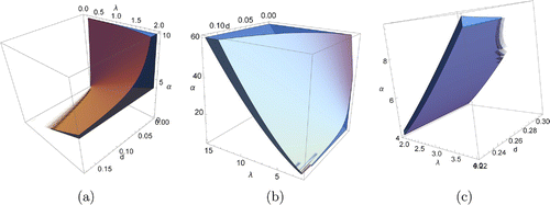
. Figure shows the parameter regions
and
in
,
, d space as volumes.
3.4. Critical values of d
When and
, the instability parameter region
is unbounded and when
and
it is bounded (Somathilake & Wedagedera, Citation2014). In order to satisfy Turing instability conditions the diffusion rate d should satisfy
(Somathilake & Wedagedera, Citation2014). Here
,
where
3.5. Effect of the fractional exponent and model parameters for the growth
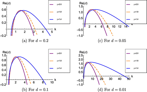
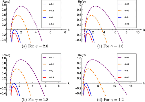
Figures and show the variation of the real part of , Re(
), with respect to k at different levels of
, and different levels of d, respectively for particular parameter values
,
lying in region
. As time increases, the solution of the system is dominated by the wave numbers corresponding to the maximum value of growth rate
.
Figure 2. The variation of the real part of , Re(
), against k at different levels of
for particular d. Note: Other parameters which lie in region
are
and
.
Consider the dispersion relation (17). Critical values of are given by
(20)
(20)
Solving (20) for we get two solutions
and
given by
where
We can show that is maximized at
. That is
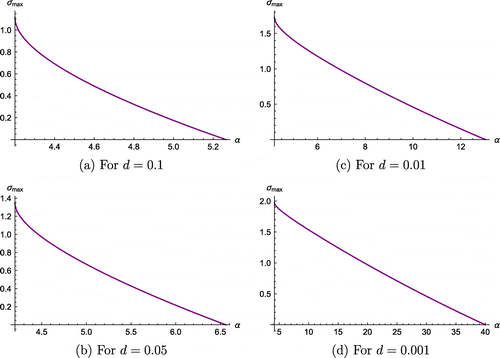
. The plots of
against
when
for different levels of d are shown in Figure .
Figure 3. (a) The variation of Re() against k at different levels of d for particular
values. Note: The other parameters that lie in region
are
,
.
It is clear that is maximized at
for given
. The wavelength corresponding to the maximum growth rate is given by
. The wave number
corresponding to the maximum growth rate is given by
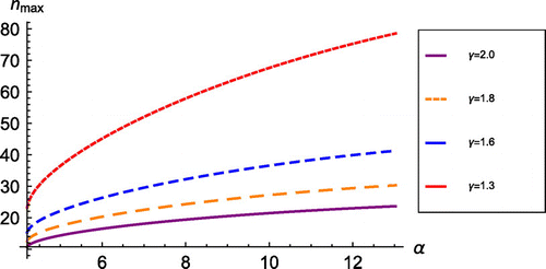
. The plot of
against
for
,
, at different levels of
is shown in Figure . We can observe that for fixed
and d, the value of
increases when
increases from 1. That is the heterogeneity of the spatial patterns increases as
increases when
,
and d are fixed. Also we observe that when both
and
increase the possible minimum and maximum values of
as well as the range of
increase. This implies that the heterogeneity of the spatial patterns increases as
and
increase when d and
are fixed.
4. Numerical methods
4.1. Fourier spectral method
The Fourier spectral method has been used in numerical computations of fractional reaction diffusion equations by several researchers (Bueno-Orovio et al., Citation2014; Bueno-Orovio & Pérez-Garca, Citation2006; Pindza & Owolabi, Citation2016). The fractional Laplace operator on a bounded domain is expressed in Bueno-Orovio et al. (Citation2014) and Ilić et al. (Citation2006) based on a set of orthonormal eigenfunctions and corresponding eigenvalues as follows:
Definition 4.1
(Ilić et al., Citation2006) Suppose the Laplacian () has a complete set of orthonormal eigenfunctions
corresponding eigenvalues
on a bounded domain
, i.e.
on
;
on
, where
is one of the three standard boundary conditions . Let
Then, for any ,
is defined by
here and
depend on the specified boundary conditions.
The boundary conditions of our model corresponding to standard diffusion are homogeneous Neumann type, and according to Cusimano et al. (Citation2017) these boundary conditions properly transfer to the fractional diffusion operator in one dimensional space. Therefore, the eigenvalues and eigenvectors of the fractional diffusion operator on a bounded domain in one dimensional space with homogeneous Neumann boundary conditions are well defined. In this paper we assume that the result holds for two dimension as well.
The eigenvalues and corresponding eigenvectors
of the discrete Laplacian operator A (see Equation (10)) on
, coupled with homogeneous Neumann boundary conditions, obtained with a finite difference approximation on a uniform mesh of
nodes with step size
, are
and
for
.
Eigenvalues of the discrete fractional Laplacian operator, , can be taken as
, since the Neumann boundary conditions of the discrete Laplacian, operator, A, properly transfer to the discrete fractional Laplacian operator,
. Another representation for the fractional order Laplace operator on
subject to standard Neumann Boundary conditions (the reflection boundary condition) has been presented in Cusimano et al. (Citation2017) and this representation is called Reflection Matrix. The Reflection matrix of fractional order
on a uniform mesh of
nodes with step size
on
is denoted as
. The Eigenvalues
of
are derived in Cusimano et al. (Citation2017) of the form:
Then for , we can show that, as h goes to zero, both
and
converge to
, which are eigenvalues of the continuous Laplacian operator on
subject to standard Neumann boundary conditions.
The discrete Laplacian on can be represented in terms of discrete Laplacians on
and
. Let
,
and A be the discrete Laplacian operators on
,
and
, respectively. Boundary conditions embedded on
,
and A should coincide. Then
, where
and
are the identity operators on
and
, respectively. Based on this result we can obtain eigenvalues and eigenvectors of discrete Laplacian on
. Let
and
denote the eigenvalues and eigenvectors of the discrete Laplace operator on
subject to homogeneous Neumann boundary conditions. Then we get
and
. Here
,
are eigenvalues of the discrete Laplacian operators subject to homogeneous Neumann boundary conditions on
and
respectively.
and
are eigenvectors of the discrete Laplace operator subject to homogeneous Neumann boundary conditions on
and
, respectively.
Consider the system of fractional diffusion Equations (11). Discretising first two equations of this system in time and treating fixed point iteration for each time step n we get the iteration processes:(21)
(21)
Then the ith Fourier mode of the time-space discretisation of (21) becomes:(22)
(22)
where ,
,
and
denote the Fourier coefficients of u, v, F and G, respectively, and
is the ith eigenvalue of the discrete Laplace operator subject to considered boundary conditions.
At each time step, iterative process (22) is initiated taking and
. After calculating
and
, the inverse reconstructions
and
in physical space can be computed by inverse Fourier transforms for the one-dimensional and two-dimensional cases.
4.2. Some other possible numerical methods
Discretising in space, a fractional reaction diffusion equation can be approximated to a system of ODEs using Matrix Transfer Technique. Then the system of ODEs can be solved using suitable numerical methods. In this section we briefly explain three possible numerical methods.
Applying the Matrix Transfer Technique, the first two equations of the system (11) can be presented in the form(23)
(23)
Here A is the discrete Laplacian operator coupled with standard boundary conditions. In one dimension, subject to Neumann boundary conditions, the matrix A is given in Equation (10). The vectors ,
,
and
represent the spatial discretisations of u, v, F and G, respectively.
, where V is the matrix in which columns are eigenvectors of A, and D is a diagonal matrix in which elements are the eigenvalues of A.
4.2.1. A semi implicit scheme
Consider the following time discretisation of the system (23):(24)
(24)
This system can be arrange in the form:(25)
(25)
where . This is a semi-implicit scheme and the systems of linear equations (25) were solved in MATLAB, using the Conjugate Gradient Scheme (CGS).
4.2.2. A fully explicit scheme
Substituting in (25) we get:
(26)
(26)
These systems of equations can be arranged in the form:(27)
(27)
Where ,
are diagonal matrices,
and
. This is a fully explicit scheme. The system (27) can be solved for
and
.
and
are given by
,
.
Also, the system of ODEs (23) was solved using the MATLAB function ODE15s that is suitable to solve stiff ODEs.
5. Numerical results
5.1. Fourier spectral method
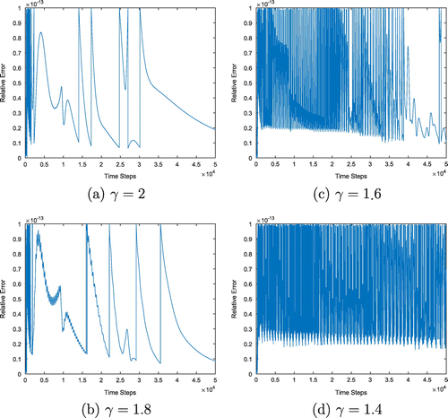
We solved the system (8) numerically, on bounded one and two dimensional domains, subject to homogeneous Neumann boundary conditions with suitably chosen initial conditions using the numerical scheme (23). In these simulations, in each time step fixed point iterations proceed until the Relative Error (RE) becomes smaller than the predefined tolerance (Tol). The relative Error at each iteration m at time step n is calculated as follows:(28)
(28)
In the following simulations, the tolerance is set as Tol .
5.1.1. In one dimension
The system (22) was simulated on in the time interval
taking the following initial conditions
(29)
(29)
Here .
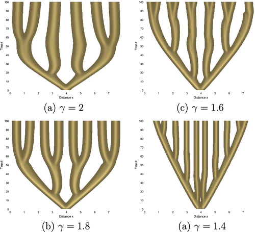
We controlled the termination of the iterative scheme (22) by applying the tolerance, Tol, to the relative error. Density plots of numerically evaluated v(x, t) for different values of are shown in Figure for
,
,
. In these simulations
,
, and the spatial and time grid sizes are
and
, respectively.
Figure illustrates the variation of the number of iterations in each time step. According to Figure , we can observe that, when decreases, the required number of iterations of the iterative process (22) increases in order to maintain the fixed predefined error tolerance. As a result of that computational time increases. Figure shows how the error defined in Equation (28), is maintained by the tolerance at each iteration. We can observe that as time passes the required number of iterations to maintain error tolerance decreases. Table shows the total number of iterations, and total computational time of the above simulations.
Figure 7. Variation of the number of iterations against number of time steps when the step size is 0.002.
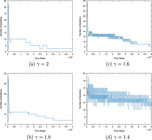
Table 1. Total number of iterations and computation time
According to Table , the total number of iterations required to maintain the tolerance, and computational time, increases as decreases.
5.1.2. In two dimension
We solved the system (22) numerically on the 2D domain, , subject to zero-flux boundary conditions and initial conditions:
(30)
(30)
Here
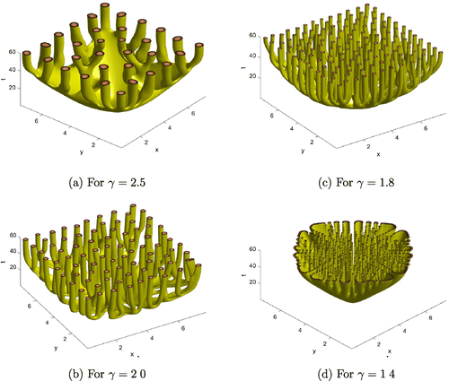
Isosurfaces of numerically evaluated for different levels of
are shown in Figures for
,
,
. In these simulations,
,
, and the spatial and time grid sizes are
and
, respectively. According to this figure, we can see that the heterogeneity of the space patterns increases as
decreases.
5.2. Comparison of numerical schemes
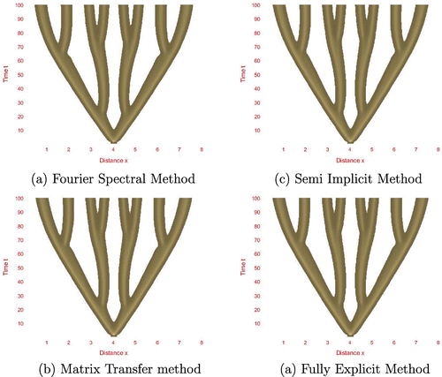
In addition to the Fourier Spectral method, we solved the system of ODEs (23) using the MATLAB function ODE15s and numerical schemes (25) and (27) in one dimensional space subject to the same boundary conditions and initial data used in numerical simulations of Section 5.1.1. Density plots of the numerical solutions, obtained using these numerical methods, are presented in Figure . The parameters used in these simulations are ,
,
and
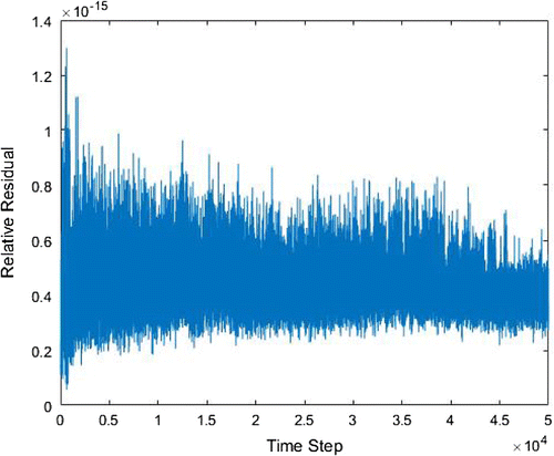
. We solved the linear systems arising at each time step of the numerical scheme (25), using the CGS method. The iteration processes of the CGS were controlled by predefined tolerance, TOL=
. We define the relative residual, RelRes, of a numerical solution of the linear system
as RelRes
. Figure shows the RelRes corresponding to the last iteration of the iterative process at each time step of the scheme (25). We can observe that RelRes of this scheme at each time step has been properly controlled by the TOL (that is the Rel-Res corresponding to last iteration of the each time step is less than the TOL). Therefore, numerical scheme (25) is convergent, and so the numerical solutions of the system (25), obtained by the above schemes, converge to a solution of the system (23).
We observed that all the density plots in Figure are almost the same. Therefore all four numerical methods, the Fourier Spectral method, MATLAB ODE15s, Semi-implicit method and Fully-Explicit method give almost the same solution of system (11).
6. Discussion and conclusions
There are three spatially homogeneous steady states ,
and
of the model and Turing type instability occurs at
only. We performed Turing instability analysis about
and observed that instability conditions do not depend on the fractional power
but the dispersion relation and the growth rate do. Figure shows the variation of Re(
) against the wave mode k for different levels of
and d. The range of unstable wave modes (the range of k) increases as
decreases when d is fixed. The wave mode correspond to the maximum growth rate,
, increases as
decreases. Also for a fixed d,
does not vary with
.
Figure shows the variation of the real part of , Re(
), against k for different levels of d. According to this figure, we can observe that when
, Re(
) increases as d decreases from
. Also, the wave mode corresponds to the maximum growth rate and the range of unstable wave modes increases as d decreases from
. These observations imply that as d decreases from
, the growth rate, of coral increases, and the heterogeneity of the coral structures increases.
Figure shows the variation of with respect to
for
. For fixed d and
the growth rate maximizes at
(if
) or at
(if
). For fixed d, as
increases from its minimum value (
or
) to a maximum value
in the Turing space, the maximum growth rate
decreases from its maximum value to 0. Furthermore, we can observe that as d decreases, the maximum growth rate,
, increases when
and
are fixed.
Figure shows the plot of (wave number corresponding to
) against
for different levels of
for
,
. We observed that
increases when
decreases while other parameters are fixed. Also,
increases as
increases from
(or
) to
while other parameters are fixed. This implies that more heterogeneous spatial patterns are generated by the solutions at larger
and smaller
values.
The parameters d, and
of the proposed model are defined as
,
and
. Turing type patterns are possible if these parameters lie in the Turing instability region. If we assume that the growth factors of coral are controlled except the nutrient availability, then it is reasonable to assume that
,
, b,
and
are fixed. Thus
and d are fixed and
depends on the nutrient supplying rate, a, only. By adjusting the nutrient supplying rate we can adjust
such that all parameters lie in the Turing instability region. Then spatial temporal patterns of coral can be expected when a sufficient perturbation from the steady state
is done, in order to make the system unstable.
According to the results shown in Figure , as increases the heterogeneity of the branching structures increases when d,
and
are fixed . That is if the nutrient supply rate increases then the heterogeneity of the branching structures increases.
Figures and shows the effect of the fractional order, , for the spatial patterns generated by the numerical solutions of the model. These numerical solutions show that the spatial heterogeneity of the solutions increases as
decreases. This behaviour matches with some of the theoretically derived results in Section 3.5. According to Figure we can conclude that numerical solutions obtained by four numerical methods explained in Section 4 are almost same.
According to Henry and Wearne (Citation2000) spatial sub-diffusion () terms arise when modelling processes with spatial constraints such as porosity and fractal lattices, and super-diffusion (
) terms arise when turbulent or chaotic behaviours appear in the media of the model. Based on this explanation we can give following physical interpretations on the effect of the parameter
of our model.
If the porosity of the media increases (that means
decreases from 2 to 1) then the heterogeneity of the patterns increases.
When the coral density of the tank increases the porosity increases. In other words as time passes the coral density increases. As a result of this, porosity increases and the heterogeneity of the coral patterns increases. Therefore it would be interesting to consider time dependent fractional orders which will be considered in future work.
As the turbulence of the media increases (so that
increases from 2) then the heterogeneity of the coral patterns decreases.
Acknowledgements
The authors would like to thank Professor Fawang Liu, School of Mathematical Sciences, Queensland University of Technology, Brisbane, Australia for giving suggestions to improve the quality of the paper. The first author greatly appreciate the support given by the School of Mathematical Sciences, Queensland University of Technology, Brisbane, Australia through a visiting fellowship position at School of Mathematical Sciences to carry out this research.
Additional information
Funding
Notes on contributors
Lekam Watte Somathilake
Lekam Watte Somathilake is currently a Senior Lecturer in Mathematics at the Department of Mathematics, Faculty of Science, University of Ruhun, Matara, Sri Lanka. He completed PhD and MPhil degrees in Mathematics at University of Ruhuna, Sri Lanka in 2012 and 2004 respectively. His research interests include Ordinary and Partial Differential Equations, Reaction Diffusion Pattern Formations, Numerical Analysis and Mathematical Biology.
Kevin Burrage
Kevin Burrage is currently a Professor of Computational Maths at the School of Mathematical Sciences, Faculty of Science and Engineering, Queensland University of Technology, Brisbane, Australia. He is also a Visiting Professor to the Department of Computer Science, University of Oxford, UK. His research interests include Computational Mathematics, Computational Biology and Systems Biology. This research was carried out while L.W. Somathilake was serving as a Visiting Fellow (from July 2016 to June 2017) under the supervision of Professor Kevin Burrage at the Queensland University of Technology, Brisbane, Australia.
References
- Benchohra, M., Henderson, J., Ntouyas, S., & Ouahab, A. (2008). Existence results for fractional order functional differential equations with infinite delay. Journal of Mathematical Analysis and Applications, 338(2), 1340–1350.
- Bhrawy, A. H., Baleanu, D., & Mallawi, F. (2015). A new numerical technique for solving fractional sub-diffusion and reaction sub-diffusion equations with a non-linear source term. Thermal Science, 19(suppl. 1), 25–34.
- Bueno-Orovio, A., Kay, D., & Burrage, K. (2014). Fourier spectral methods for fractional-in-space reaction-diffusion equations. BIT Numerical Mathematics, 54(4), 937–954.
- Bueno-Orovio, A., & Pérez-García, V. M. (2006). Spectral smoothed boundary methods: the role of external boundary conditions. Numerical Methods for Partial Differential Equations, 22(2), 435–448.
- Burrage, K., Hale, N., & Kay, D. (2012). An efficient implicit fem scheme for fractional-in-space reaction-diffusion equations. SIAM Journal on Scientific Computing, 34(4), A2145–A2172.
- Cusimano, N., Burrage, K., Turner, I., & Kay, D. (2017). On reflecting boundary conditions for space-fractional equations on a finite interval: Proof of the matrix transfer technique. Applied Mathematical Modelling, 42, 554–565.
- Diethelm, K., & Freed, A. D. (1999). On the solution of nonlinear fractional-order differential equations used in the modeling of viscoplasticity. In Scientific Computing in Chemical Engineering II (pp. 217–224). Heidelberg: Springer.
- Henry, B. I., & Wearne, S. L. (2000). Fractional reaction-diffusion. Physica A: Statistical Mechanics and its Applications, 276(3), 448–455.
- Henry, B. I., Langlands, T., & Wearne, S. (2005). Turing pattern formation in fractional activator-inhibitor systems. Physical Review E, 72(2), 026101.
- Hilfer, R. (2000). Applications of fractional calculus in physics. River Edge, NJ: World Scientific.
- Ilic, M., Liu, F., Turner, I., & Anh, V. (2005). Numerical approximation of a fractional-in-space diffusion equation, i. Fractional Calculus and Applied Analysis, 8(3), 323–341.
- Ilic, M., Liu, F., Turner, I., & Anh, V. (2006). Numerical approximation of a fractional-in-space diffusion equation (ii)-with nonhomogeneous boundary conditions. Fractional Calculus and applied analysis, 9(4), 333–349.
- Jafari, H., Tajadodi, H., Baleanu, D., Al-Zahrani, A. A., Alhamed, Y. A., & Zahid, A. H. (2013). Fractional sub-equation method for the fractional generalized reaction duffing model and nonlinear fractional sharma-tasso-olver equation. Central European Journal of Physics, 11(10), 1482–1486.
- Kaandorp, J. A., Lowe, C. P., Frenkel, D., & Sloot, P. M. A. (1996). Effect of nutrient diffusion and flow on coral morphology. Physical Review Letters, 77(11), 2328–2331.
- Kaandorp, J. A., Sloot, P. M. A., Merks, R. M. H., Bak, R. P. M., Vermeij, M. J. A., & Maier, C. (2005). Morphogenesis of the branching reef coral madracis mirabilis. Philosophical Transactions of the Royal Society B, 77, 127–133.
- Kaandorp, J. A., Blom, J. G., Verhoef, J., Filatov, M., Postma, M., & Müller, W. E. G. (2008). Modelling genetic regulation of growth and form in a branching sponge. Philosophical Transactions of the Royal Society B, 275, 2569–2575. doi:10.1098/rspb.2008.0746
- Kirane, M., Ahmad, B., Alsaedi, A., & Al-Yami, M. (2014). Non-existence of global solutions to a system of fractional diffusion equations. Acta Applicandae Mathematicae, 133(1), 235–248.
- Li, B., & Wang, J. (2003). Anomalous heat conduction and anomalous diffusion in one-dimensional systems. Physical Review Letters, 91(4), 044301.
- Liu, F., Yang, Q., & Turner, I. (2011). Two new implicit numerical methods for the fractional cable equation. Journal of Computational and Nonlinear Dynamics, 6(1), 011009.
- Merks, R. M. H. (2003a). Branching growth in Stony Corals a modelling approach. Advaced School of Computing and Imaging (PhD thesis). University of Amsterdam.
- Merks, R. M. H. (2003b). Models of coral growth: Spontaneous branching, compactification and laplacian growth assumption. Journal of Theoretical Biology. 224, (2), 153–166
- Merks, R. M. H., Hoekstra, A., Kaandorp, J. A., & Sloot, P. (2003a). Diffusion-limited aggregation in laminar flows. International Journal of Modern Physics C, 14(9), 1171–1182.
- Merks, R. M. H., Hoekstra, A., Kaandorp, J. A., & Sloot, P. (2003b). A problem solving environment for modelling stony coral morphogenesis. In International Conference on Computational Science, ICCS 2003, 639–648.
- Metzler, R., & Klafter, J. (2000). The random walk’s guide to anomalous diffusion: A fractional dynamics approach. Physics Reports, 339(1), 1–77.
- Mistr, S., & Bercovici, D. (2003). A theoretical model of pattern formation in coral reefs. Ecosystems, 6, 61–74.
- Murray, J. D. (2003). Mathematical Biology: Spatial models and biomedical applications (Vol. II). Berlin Heidelberg: Springer-Verlag.
- Pindza, E., & Owolabi, K. M. (2016). Fourier spectral method for higher order space fractional reaction-diffusion equations. Communications in Nonlinear Science and Numerical Simulation, 40, 112–128.
- Rida, S., El-Sayed, A., & Arafa, A. (2010). On the solutions of time-fractional reaction-diffusion equations. Communications in Nonlinear Science and Numerical Simulation, 15(12), 3847–3854.
- Sabatier, J., Agrawal, O. P. & Machado, J. T. (2007). Advances in fractional calculus (Vol. 4). Dordrecht: Springer.
- Santoro, P., de Paula, J., Lenzi, E., & Evangelista, L. (2011). Anomalous diffusion governed by a fractional diffusion equation and the electrical response of an electrolytic cell. The Journal of chemical physics, 135(11), 114704.
- Schiessel, H., Metzler, R., Blumen, A., & Nonnenmacher, T. (1995). Generalized viscoelastic models: Their fractional equations with solutions. Journal of physics A: Mathematical and General, 28(23), 6567.
- Somathilake, L. W., & Wedagedera, J. R. (2012). On the stability of a mathematical model for coral growth in a tank. British Journal of Mathematics and Computer Science, 2(4), 255–280.
- Somathilake, L. W., & Wedagedera, J. R. (2014). A reaction-diffusion type mathematical model for formation of coral patterns. Journal of National Science Foundation, 42(4), 341–349.
- Sun, H., Chen, W., & Chen, Y. (2009). Variable-order fractional differential operators in anomalous diffusion modeling. Physica A: Statistical Mechanics and its Applications, 388(21), 4586–4592.
- Tchier, F., Inc, M., Korpinar, Z. S., & Baleanu, D. (2016). Solutions of the time fractional reaction-diffusion equations with residual power series method. Advances in Mechanical Engineering, 8(10), 1687814016670867.
- Tian, W., Zhou, H., & Deng, W. (2015). A class of second order difference approximations for solving space fractional diffusion equations. Mathematics of Computation, 84(294), 1703–1727.
- Turing, A. M. (1952). The chemical basis of morphogenesis. Philosophical Transactions of the Royal Society of London, 237(641), 37–72.
- Upadhyaya, A., Rieu, J.-P., Glazier, J. A., & Sawada, Y. (2001). Anomalous diffusion and non-gaussian velocity distribution of hydra cells in cellular aggregates. Physica A: Statistical Mechanics and its Applications, 293(3), 549–558.
- Yang, Q., Liu, F., & Turner, I. (2010). Numerical methods for fractional partial differential equations with riesz space fractional derivatives. Applied Mathematical Modelling, 34(1), 200–218.
- Yu, Q., Liu, F., Anh, V., & Turner, I. (2008). Solving linear and non-linear space-time fractional reaction-diffusion equations by the adomian decomposition method. International Journal for Numerical Methods in Engineering, 74(1), 138–158.
- Zhuang, P., Liu, F., Anh, V., & Turner, I. (2009). Numerical methods for the variable-order fractional advection-diffusion equation with a nonlinear source term. SIAM Journal on Numerical Analysis, 47(3), 1760–1781.

