 ?Mathematical formulae have been encoded as MathML and are displayed in this HTML version using MathJax in order to improve their display. Uncheck the box to turn MathJax off. This feature requires Javascript. Click on a formula to zoom.
Abstract
An application of support vector machine (SVM) to compute the resonant frequency at dominant mode TM11 of annular ring compact microstrip antennas (ARCMAs) is presented in this paper. ARCMAs have some useful features; resonant modes can be adjusted by controlling the ratio of the outer radius to the inner radius. The resonant frequencies of 100 ARCMAs with varied dimensions and electrical parameters in accordance with UHF band covering GSM, LTE, WLAN, and WiMAX applications were simulated with IE3D™ which is a robust numerical electromagnetic computational tool. Then, the SVM model was built with simulation data and 88 simulated ARCMAs were operated for training and the remaining 12 ARCMAs were used for testing this model. The proposed model has been confirmed by comparing with the suggestions reported elsewhere via measurement data published earlier in the literature, and it has further validated on an ARCMA operating at 3 GHz fabricated in this study. The obtained results show that this technique can be successfully used to compute the resonant frequency of ARCMAs without involving any sophisticated methods. The novelty of the approach described here is to offer ease of designing the process using this method.
Public Interest Statement
The wireless communication devices such as laptop, netbook, and smart phone are moving toward the miniaturization very rapidly. Therefore, the antennas within these mobile devices should also be reduced in size with high performance, as well. Thus, compact microstrip antennas can be one of the best choices, since they allow to easily modify their geometry in order to achieve the desired characteristics. Annular ring compact microstrip antennas are miniaturized by loading a circular slot in the center of the circular patch. The resonant frequency determination of compact microstrip antennas is important, because these antennas inherently suffer from narrow bandwidth. The support vector machine is a recent and effective artificial intelligent technique as artificial neural network and adaptive neuro-fuzzy inference system. In this study, a method based on support vector machine model has been successfully used for determining the resonant frequency of annular ring compact microstrip antennas.
1. Introduction
Microstrip antennas (MAs) are preferred in a wide range of applications such as aircraft antennas, missile guidance antennas, mobile radios, and array antennas due to their advantageous features as being low profile, having low fabrication costs, and ease of integration with microwave circuits. However, MAs also have some disadvantageous characteristics like having narrow bandwidth and low power handling capacity. Therefore, there has been a vast amount of researches on proposing alternative MA configurations that could eliminate the drawbacks of conventional MAs. As alternative antenna configurations, introduction of parasitic patches and modifying the shape of the microstrip patch are proposed (Wong, Citation2002).
Present portable communication and handheld devices inherently need miniaturized MAs. Using the substrate materials with high dielectric constant, the smaller antennas can be achieved, but this gives rise to decrease the bandwidth and efficiency performances (Kumar & Ray, Citation2003; Wong, Citation2002). Thus, it is difficult to carry out the requirements of mobile communication devices by using the traditional MAs. The compact geometry has been proved as an alternate methodology to design miniature MAs. The compact microstrip antennas (CMAs) are obtained by applying some modifications such as slot-loading and shorting-pin/wall on traditional MA structures (Wong, Citation2002). Several slot-loaded CMA configurations such as C (Deshmukh & Kumar, Citation2007), E (Akdagli, Toktas, Kayabasi, & Develi, Citation2013; Deshmukh, Phatak, Nagarbovdi, & Ahuja, Citation2013), H (Deshmukh & Kumar, Citation2007; Kayabasi, Bicer, Akdagli, & Toktas, Citation2011), L (Chen, Citation2000), rectangular ring (Deshmukh & Kumar, Citation2007), and annular ring (Chew, Citation1982) shapes have been presented in the literature as an alternative and effective method to reduce the physically size of antenna.
Annular ring compact microstrip antennas (ARCMAs) are miniaturized antenna constructed by loading a circular slot in the center of the circular patch. The size of the ARCMA is substantially smaller than circular microstrip antenna (CMA) at the same operating frequency (Chew, Citation1982). It can be appreciated that the average path length traveled by the current in the annular-ring patch is much longer than the corresponding circular patch for the lowest order mode (Chew, Citation1982). Also, by choosing the inner and outer radius of the ring properly, both bandwidth broadening (Chew, Citation1982) and controlling the separation of resonant modes can be managed (Dahele, Lee, & Wong, Citation1987). Due to these useful properties, it is one of the most studied MAs. In the literature, the ARCMA was theoretically investigated by its resonator model in (Bahl, Stuchly, & Stuchly, Citation1980; Wolff & Knoppik, Citation1971; Pintzos & Pregla, Citation1978; Wu & Rosenbaum, Citation1973). The mathematical tools such as vector Hankel transform, Galerkin’s method, and Green functions were greatly utilized in the analysis of the ARCMAs (Ali, Weng, & Kong, Citation1982; Fan & Lee, Citation1991; Gurel & Yazgan, Citation2010; Liu & Hu, Citation1996a, Citation1996b; Motevasselian, Citation2011). Methods based on cavity model and transmission line model were presented to investigate some parameters such as the resonant frequency, input impedance, and bandwidth (Bahl & Stuchly, Citation1992; Bhattacharyya & Garg, Citation1985; El-khamy, El-Awadi, & El-Sharrawy, Citation1986; Gomez-Tagle & Christodoulou, Citation1997; Kumar & Dhubkarya, Citation2011; Richards, Jai-Dong, & Long, Citation1984; Sathi, Ghobadi, & Nourinia, Citation2008). The experimental studies concerning the ARCMA were also performed to confirm the theoretical calculations in Dahele et al. (Citation1987), Bahl et al. (Citation1980), Fan and Lee (Citation1991), Liu and Hu (Citation1996a), Kumar and Dhubkarya (Citation2011), Dahele and Lee (Citation1982), Lee, Dahele, and Ho (Citation1983), Row (Citation2004), and Shinde, Shinde, Kumar, Uplane, and Mishra (Citation2010). It can be seen from the literature that these methods include rigorous calculation of Hankel and Fourier transforms and Bessel functions.
Analytical methods seem to be easier but they result in accurate solutions only for regular shapes of the patch, whereas the numerical electromagnetic computation methods are suitable for all shapes of the MA. However, the numerical methods require much more time in solving Maxwell’s equations including integral and/or differential computations. So, it becomes time consuming since it repeats the same mathematical procedure even if a minor change in geometry is carried out. On the other hand, antenna designers prefer the easier approaches without requiring much rigorous computations and consuming time.
Due to the rapid development of computer technology in recent years, several robust and alternative methods based on nature-inspired optimization algorithms and artificial intelligent techniques (AITs) have emerged for solving the different kind of engineering problems. The most well-known AITs are the artificial neural network (ANN) (Kumar & Shukla, Citation2012), the adaptive neuro-fuzzy inference system (Dadgarnia & Heidari, Citation2010), and the support vector machine (SVM) (Bertsekas, Citation1995; Christodoulou, Martinez-Ramon, & Balanis, Citation2006; Cristianini & Shawe-Taylor, Citation2000; Tokan, Citation2008; Tokan & Gunes, Citation2008; Vapnik, Citation1998). AITs, which are effective and high speedy approaches, are used frequently for the solution of microwave and electromagnetic problems in recent years.
In machine learning, SVM is a new generation supervised learning model which is used for classification and regression analysis. In another terms, SVM is a classification and regression prediction tool that uses machine learning theory to maximize predictive accuracy while automatically avoiding over-fit to the data. The SVM is an advanced nonlinear learning machine (so-called Vapnik–Chervonenkis theory) (Vapnik, Citation1998). SVM is a machine learning method used for classification and regression implementations and also run in supervised or semi-supervised way. In the nonlinear problems such as ours, SVM depends on the principle which is separation of two classes with a hyperplane that is occurred by transforming data into the higher dimensions. The functions that have various features are used during the transformation into the high dimension and these functions are called as Kernel functions. Some parameters in the mathematical expression of these functions need to be defined by the user for using Kernel functions. SVM has been formed on powerful theoretical foundations (Tokan & Gunes, Citation2008). A distinct advantage of SVM is that it bypasses the repeated use of complex formulations or process for a new case given to it after proper training.
In this study, an application of SVM model is presented to compute accurately resonant frequencies of ARCMAs. The resonant frequency values of 100 ARCMAs corresponding most of UHF band covering GSM, LTE, WLAN, and WiMAX applications were determined by the electromagnetic simulator IE3D™ using method of moment (Harrington, Citation1993). The simulation parameters of 88 ARCMAs representing the overall problem space were used for training and the remaining 12 were then employed to test the accuracy. The results of the SVM model obtained in this study were confirmed by comparing with the measurement results published earlier in the literature (Bahl et al., Citation1980; Dahele & Lee, Citation1982; Dahele et al., Citation1987; Fan & Lee, Citation1991; Kumar & Dhubkarya, Citation2011; Lee et al., Citation1983; Liu & Hu, Citation1996a; Row, Citation2004; Shinde et al., Citation2010). Furthermore, the accuracy and validity of the proposed method of the SVM model was also verified on an ARCMA prototyped in this work.
2. SVM Modeling for computation the resonant frequency of ARCMAs
2.1. Support vector machine
In machine learning, SVM is a new generation supervised learning model (Christodoulou et al., Citation2006). N-dimension optimum hyperplane that separated two groups into data is occurred by the SVM. The SVM model is closely associated with ANN and it has an artificial network consisting of the two layers and feed-forward. An empirical risk minimization derived by minimizing the squares of the error on the data-set is not used by the SVM. It separates two groups into data by using the structural risk minimization in statistical learning theory. The SVM can be used in the classification and regression problems. The basic idea in the SVM regression method is determined by a linear discriminant function reflecting the characteristics of data-set. This function used for classification, regression, or other tasks is called hyperplane or margin. The SVM effectively constructs a maximum hyperplane (maximum margin) having equidistant from both of the data in a high or infinite dimensional space. The SVM can solve a problem having a linear or nonlinear structure. It easily finds a solution for linearly separable problems. However, this method used to solve the linearly separable problem is not sufficient for nonlinear problem. One way to solve this problem is to map the data on to a higher dimensional space and then to use a linear classifier in the higher dimensional space. This mapping to a higher dimensional space in SVM is performed by using kernel function (Vapnik, Citation1998).
In this paper, the SVM was used to predict the resonant frequency (fr) of ARCMAs. The problem related to the estimation of the fr can be stated as follows. In the training process, the training data have been taken as a set of m training pairs {(x0, fr0), (x1, fr1), … (xm, frm)} by considering x as the input variable vector and fr as the output. x is physical dimensions (ao, ai, and h) and dielectric constant values (εr) of the simulated ARCMAs and fr is also resonant frequencies of ARCMAs. Given a set of observed discrete data {(xi, fri), xi Є R, fri Є R, i = 1, 2, …, m}, the SVM learning method in its basic form creates an fr*(x) function. Starting from these samples of the input/output values of fr, the goal is to find a function fr*(x), which approximates, as well as is a possible unknown function fr(x). Using the support vector regression, fr* is defined as:(1)
(1)
where denotes the inner product, and φ is a nonlinear mapping vector that performs a transformation of the input vector to a high dimensional space. The patterns that are not linearly separable are extended to a new higher dimension space where it is possible to separate them with a linear hyperplane. w and b are the weighting vector and bias, respectively, which are obtained by minimizing the primal convex objective function (Regression Risk) defined as:
(2)
(2)
(3)
(3)
(4)
(4)
where ξi are called slack variables and they are used for measuring the occurred error at point (xi, fri). C is a deterministic parameter that shows the change rate of the size of the margin and amount of error in training process and mε(x, fr) is a general loss function. Since the given objective function Equation 2 has no local minima and it guarantees the global minimum, which is one superiority of SVM on the other pattern recognition methods, particularly neural networks.
In our work, the so-called ε-insensitive loss function developed by Vapnik (Citation1998) is used:(5)
(5)
This defines an ε tube so that if the predicted value is within the tube, the loss is zero, while if the predicted point is outside the tube, the loss is the magnitude of the difference between the predicted value and the radius of the tube.
This primal problem is transformed into dual problem, and then it can be solved by using Lagrange multipliers method (Bertsekas, Citation1995). The Lagrange function, J can be given as;(6)
(6)
This primal problem is not preferred for solving. Therefore, this primal problem is transformed into dual problem. At this point, there are usually two main reasons mentioned for solving this problem in the dual:
The duality theory provides a convenient way to deal with constraints.
The dual optimization problem can be written in terms of dot product, thereby making it possible to use kernel functions.
The dual problem has the same optimal value as the primal problem. To describe the dual problem, Equation 6 is expanded as:
Maximize(7)
(7)
subject to(8)
(8)
(9)
(9)
The acquired dual problem can be solved by quadratic programming techniques. Here, α1, α2, … αi are Lagrange multipliers that correspond each sample. The Karush–Kuhn Tucker theorem is important for this optimization problem (Cristianini & Shawe-Taylor, Citation2000). The theorem is essential for solving the w, b, and α parameters. While the values of α are greater than zero, the expression in Equation 11 is applied for each training point. When the values of α are equal to zero, the points are excluded for not affecting the hyperplane. The values of the α* are assumed to be the best solution for the dual problem. The expressions for the solution of w and b are given, respectively, as follows:.(10)
(10)
(11)
(11)
x vector can be expressed as in Equation 12:(12)
(12)
The decision function obtained by using the kernel function is given in Equation 13:(13)
(13)
Some common kernel functions are given below:
Linear kernel function →
It is given by the inner product <x, y> plus an optional constant c.
Polynomial kernel function →
Adjustable parameters are the slope α, the constant term c, and the polynomial degree d.
Gaussian kernel function →
The adjustable parameter σ plays a major role in the performance of the kernel, and should be carefully tuned to the problem at hand.
Exponential kernel function →
Laplacian kernel function →
Different kernel functions have been tried for our problem in SVM model. The best results have been obtained with Gaussian kernel function. So, Gaussian kernel function was used for SVM model in this work. After several trials, value of σ was found as 28, which yielded satisfactorily results, and was employed in this work.
2.2. Geometry of ARCMAs and simulation phase
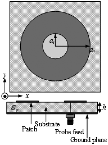
As shown in Figure , ARCMA has an annular ring patch formed by loading a circular slot with radius ai on a circular patch of radius ao on the substrate having overall relative dielectric constant εr on the ground plane.
In order to determine the resonant frequency values, simulations were performed by means of the IE3D™ software for 100 ARCMAs having different dimensions and various substrate dielectric constants which are tabulated in Table . The antennas operate over the frequency range 0.55–3.71 GHz corresponding to UHF band. In the simulations, the antennas were supposed to a probe feed with 50 Ω. For meshing process, cell/wavelength rate values were assumed as 40 in limit of 4 GHz. The built-in optimization module of the IE3D™ was utilized to determine the feed point that gives the best return loss value with the objective function S11 (dB) < −10 for the resonant frequencies at TM11 mode.
Table 1. Physical and electrical parameters of simulated ARCMAs
2.3. Training and test phases of the SVM model
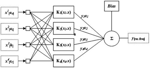
The physical dimensions (ao, ai, and h) and dielectric constant values (εr) of the simulated ARCMAs were given as inputs and their respective resonant frequency values of IE3D™ were given as output to the SVM model. For this model, 88 of ARCMAs are employed for training phase, while 12 of ARCMAs are used for test phase. The block diagram of SVM model is shown in Figure . The parameters of the SVM model used in this work are tabulated in Table . To evaluate the performances of the constructed model for both training and test, the following average percentage error (APE) equation is assigned:
Table 2. The SVM parameters
(14)
(14)
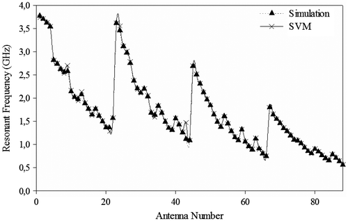
As shown in Figure , resonant frequency values, which are computed by SVM, and results obtained from simulations are in a good harmony and APE was calculated as 0.952% for the training data.
To test the performances of the SVM model constructed here, 12 simulated ARCMAs whose electrical and psychical parameters listed in Table are employed. The predicted resonant frequency results and corresponding percentage errors of the SVM model are tabulated in Table . For further comparison, the numerical results of several methods previously published in the literature (Bahl & Stuchly, Citation1992; Kumar & Dhubkarya, Citation2011; Pintzos & Pregla, Citation1978; Wu & Rosenbaum, Citation1973) are also listed in Table . It is apparent from Table that all the SVM model give the remarkable results in comparison with those calculated by the methods presented in the literature (Bahl & Stuchly, Citation1992; Kumar & Dhubkarya, Citation2011; Pintzos & Pregla, Citation1978; Wu & Rosenbaum, Citation1973).
Table 3. Physical and electrical parameters of 10 simulated ARCMAs for test process
Table 4. The resonant frequencies and APE values for test process
3. Numerical results and fabrication of ARCMA
To verify the validity of the proposed models, the resonant frequency results computed in this study were also compared with those of several suggestions reported elsewhere (Bahl & Stuchly, Citation1992; Kumar & Dhubkarya, Citation2011; Pintzos & Pregla, Citation1978; Wu & Rosenbaum, Citation1973) over several measurement data of ARCMAs published earlier in the literature (Bahl et al., Citation1980; Dahele & Lee, Citation1982; Dahele et al., Citation1987; Fan & Lee, Citation1991; Lee et al., Citation1983; Liu & Hu, Citation1996a; Kumar & Dhubkarya, Citation2011; Row, Citation2004; Shinde et al., Citation2010), and over an ARCMA fabricated with the material of Rogers™ TMM 4, as well. Table shows physical and electrical parameters of ARCMAs published earlier in the literature (Bahl et al., Citation1980; Dahele & Lee, Citation1982; Dahele et al., Citation1987; Fan & Lee, Citation1991; Lee et al., Citation1983; Liu & Hu, Citation1996a; Kumar & Dhubkarya, Citation2011; Row, Citation2004; Shinde et al., Citation2010).
Table 5. Physical and electrical parameters of of ARCMAs published earlier in literature
The computed resonant frequency values and corresponding APEs have been given in Table . The resonant frequency results simulated by using IE3DTM and HFSSTM are also given in Table so as to confirm the simulations performed in this study. It is shown that our simulated results are well agreed with measured ones. It is clearly seen from Table that our resonant frequency results are generally in very good agreement with the measured results as compared to those calculated by other suggestions (Bahl & Stuchly, Citation1992; Kumar & Dhubkarya, Citation2011; Pintzos & Pregla, Citation1978; Wu & Rosenbaum, Citation1973). Moreover, the proposed model here not only provides the better agreement but also allows us to compute the resonant frequency of ARCMA in a very simple manner without dealing with any other complicated functions and transformations.
Table 6. The measured and calculated resonant frequencies for ARCMAs
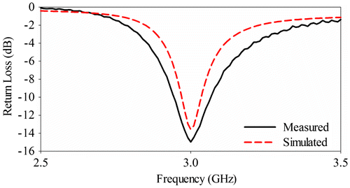
The accuracy and validity of the proposed models were also tested on the measurement data of ARCMA, which was fabricated in this work. The simulated and measured return loss plots obtained by means of Agilent E5071B ENA Series RF network analyzer were illustrated in Figure . Notice that the measurement results may include some tolerances because of material production, geometry etching, and feed connector misalignment in the fabrication process. The measured and computed resonant frequency results of the antenna are also given in Table , and it can be seen that the proposed model for resonant frequency of the ARCMA provides the best fit with the measurement.
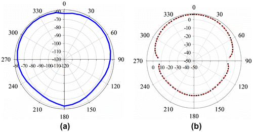
Figure shows the measured two-dimensional (2D) radiation patterns Eθ and Eϕ fields for the fabricated ARMA at 3 GHz. It is seen that the radiation patterns have good performance and approach omnidirectional radiation characteristics. The measured gain and half-power beam width (HPBW) achieved are 6.545 dBi and 110.5°, respectively.
4. Conclusion
In this paper, an application of SVM model is successfully implemented for the prediction of accurate resonant frequency of ARCMAs. IE3D™ simulation software was used to define resonant frequency of 100 ARCMAs. SVM model, physically, and electrical parameters of 88 ARCMAs were utilized training data; 12 ARCMAs were utilized for the test. It was seen that computed results with SVM for training and test data are in a good agreement with the simulation results. This method achieves the more accurate results as compared with those of the methods proposed in the literature. Additionally for validation study of our model, ARCMA is fabricated and measurement result is found in good agreement with the SVM result. The SVM approach is simple and fast modeling which produces more accurate results for the resonant frequency of the ARCMAs with less computational time and least errors. The most important advantages of this model are accuracy and easy to implement for the engineering problems which include the high nonlinearity.
Additional information
Funding
Notes on contributors
Ahmet Kayabasi
Ahmet Kayabasi was born in 1980. In 2001, he received B.S. degree in Electrical and Electronics Engineering from Selcuk University, Turkey. In 2005, he received M.S. degree in Electrical and Electronics Engineering from Selcuk University, Turkey. He has been working as a lecturer at Electronics and Automation Department of Silifke-Tasucu Vocational School of Selcuk University since 2001. He has been studying toward the PhD degree at Electrical and Electronics Engineering from Mersin University since 2009. His current research interests include antennas, microstrip antennas, computational electromagnetic, artificial intelligent, and applications of optimization algorithms to electromagnetic problem such as radiation, resonance, and bandwidth.
References
- Akdagli, A., Toktas, A., Kayabasi, A., & Develi, I. (2013). An application of artificial neural network to compute the resonant frequency of E-shaped compact microstrip antennas. Journal of Electrical Engineering - Elektrotechnicky Casopis, 64, 317–322.
- Ali, S. M., Weng, C., & Kong, J. (1982). Vector Hankel transform analysis of annular-ring microstrip antenna. IEEE Transactions on Antennas and Propagation, 30, 637–644.10.1109/TAP.1982.1142870
- Bahl, I. J., & Stuchly, S. S. (1992). Closed-form expressions for computer-aided design of microstrip ring antennas. International Journal of Microwave and Millimeter-Wave Computer-Aided Engineering, 2, 144–154.10.1002/(ISSN)1522-6301
- Bahl, I. J., Stuchly, S. S., & Stuchly, M. A. (1980). A new microstrip radiator for medical applications. IEEE Transactions on Microwave Theory and Techniques, 28, 1464–1469.10.1109/TMTT.1980.1130268
- Bertsekas, D. P. (1995). Nonlinear programming. Belmont, MA: Athena Scientific.
- Bhattacharyya, A. K., & Garg, R. (1985). Input impedance of annular ring microstrip antenna using circuit theory approach. IEEE Transactions on Antennas and Propagation, 33, 369–374.10.1109/TAP.1985.1143584
- Chen, Z. N. (2000). Radiation pattern of a probe fed L-shaped plate antenna. Microwave and Optical Technology Letters, 27, 410–413.10.1002/(ISSN)1098-2760
- Chew, W. (1982). A broad-band annular-ring microstrip antenna. IEEE Transactions on Antennas and Propagation, 30, 918–922.10.1109/TAP.1982.1142913
- Christodoulou, C., Martinez-Ramon, M., & Balanis, C. (2006). Support vector machines for antenna array processing and electromagnetics. San Rafael, CA: Morgan & Claypool Publishers.
- Cristianini, N., & Shawe-Taylor, J. (2000). An introduction to support vector machines and other kernel-based learning methods. Cambridge: Cambridge University Press.10.1017/CBO9780511801389
- Dadgarnia, A., & Heidari, A. A. (2010). A fast systematic approach for microstrip antenna design and optimization using ANFIS and GA. Journal of Electromagnetic Waves and Applications, 24, 2207–2221.10.1163/156939310793699037
- Dahele, J. S., & Lee, K. F. (1982). Characteristics of annular-ring microstrip antenna. Electronics Letters, 18, 1051–1052.10.1049/el:19820718
- Dahele, J. S., Lee, K. F., & Wong, D. (1987). Dual-frequency stacked annular-ring microstrip antenna. IEEE Transactions on Antennas and Propagation, 35, 1281–1285.10.1109/TAP.1987.1143997
- Deshmukh, A. A., & Kumar, G. (2007). Formulation of resonant frequency for compact rectangular microstrip antennas. Microwave and Optical Technology Letters, 49, 498–501.10.1002/(ISSN)1098-2760
- Deshmukh, A. A., Phatak, N. V., Nagarbovdi, S., & Ahuja, R. (2013). Analysis of broadband E-shaped microstrip antennas. International Journal of Computer Applications, 80, 0975–8887.
- El-khamy, S. E., El-Awadi, R. M., & El-Sharrawy, E. B. A. (1986). Simple analysis and design of annular ring microstrip antennas. IEE Proceedings H Microwaves, Antennas and Propagation, 133, 198–202.10.1049/ip-h-2.1986.0035
- Fan, Z., & Lee, K. F. (1991). Hankel transform domain analysis of dual-frequency stacked circular-disk and annular-ring microstrip antennas. IEEE Transactions on Antennas and Propagation, 29, 867–870.
- Gomez-Tagle, J., & Christodoulou, C. G. (1997). Extended cavity model analysis of stacked microstrip ring antennas. IEEE Transactions on Antennas and Propagation, 45, 1626–1635.10.1109/8.650074
- Gurel, C. S., & Yazgan, E. (2010). Analysis of annular ring microstrip patch on uniaxial medium via Hankel transform domain immittance approach. Progress in Electromagnetics Research M, 11, 37–52.10.2528/PIERM09071404
- Harrington, R. F. (1993). Field computation by moment methods. Piscataway, NJ: IEEE Press.10.1109/9780470544631
- Kayabasi, A., Bicer, M. B., Akdagli, A., & Toktas, A. (2011). Computing resonant frequency of H-shaped compact microstrip antennas operating at UHF band by using artificial neural networks. Journal of the Faculty of Engineering and Architecture of Gazi University, 26, 833–840.
- Kumar, R., & Dhubkarya, D. C. (2011). Design and analysis of circular ring microstrip antenna. Global Journal of Researches in Engineering, 11, 10–14.
- Kumar, G., & Ray, K. P. (2003). Broadband microstrip antennas. Norwood, MA: Artech House.
- Kumar, A., & Shukla, C. K. (2012). Artificial neural network employed to design annular ring microstrip antenna. International Journal on Computer Science and Engineering, 4, 556–564.
- Lee, K.F., Dahele, J.S., & Ho, K.Y. (1983). Annular-ring and circular-disc microstrip antennas with and without air gaps. In 13th European Microwave Conference (pp. 389–394). Nurnberg, Germany.
- Liu, H., & Hu, X. F. (1996a). An improved method to analyze the input impedance of microstrip annular-ring antennas. Journal of Electromagnetic Waves and Applications, 10, 827–833.10.1163/156939396X00801
- Liu, H., & Hu, X. F. (1996b). Input impedance analysis of microstrip annular ring antenna with thick substrate. Progress in Electromagnetic Research, 12, 177–204.
- Motevasselian, A. (2011). Specteral domain analysis of resonant characteristics and radiation patterns of a circular disk and annular ring microstrip antenna on uniaxial substrate. Progress in Electromagnetics Research, 21, 237–251.10.2528/PIERM11091002
- Pintzos, S. G., & Pregla, R. (1978). A simple method for computing the resonant frequencies of microstrip ring resonators. IEEE Transactions on Microwave Theory and Techniques, 26, 809–813.10.1109/TMTT.1978.1129491
- Richards, W. F., Jai-Dong, O., & Long, S. (1984). A theoretical and experimental investigation of annular, annular sector, and circular sector microstrip antennas. IEEE Transactions on Antennas and Propagation, 32, 864–867.10.1109/TAP.1984.1143432
- Row, J. S. (2004). Dual-frequency circularly polarised annular-ring microstrip antenna. Electronics Letters, 40, 153–154.10.1049/el:20040123
- Sathi, V., Ghobadi, C. H., & Nourinia, J. (2008). Optimization of circular ring microstrip antenna using genetic algorithm. International Journal of Infrared and Millimeter Waves, 29, 897–905.10.1007/s10762-008-9382-5
- Shinde, J., Shinde, P., Kumar, R., Uplane, M. D., & Mishra, B. K. (2010). Resonant frequencies of a circularly polarized nearly circular annular ring microstrip antenna with superstrate loading and airgaps. In Kaleidoscope: Innovations for future networks and services (pp. 1–7). Pune, India.
- Tokan, N. T. (2008, April). Support vector design of the microstrip antenna. Signal Processing, Communications and Applications, SIU 2008, IEEE 16th (pp. 1–4). Aydin.10.1109/SIU.2008.4632716
- Tokan, N. T., & Gunes, F. (2008). Support vector characterization of the microstrip antennas based on measurements. Progress in Electromagnetics Research B, 5, 49–61.10.2528/PIERB08013006
- Vapnik, V. N. (1998). Statistical learning theory. New York, NY: Wiley.
- Wolff, I., & Knoppik, N. (1971). Microstrip ring resonator and dispersion measurement on microstrip lines. Electronics Letters, 7, 779–781.10.1049/el:19710532
- Wong, K. (2002). Compact and broadband microstrip antennas. New York, NY: Wiley.10.1002/0471221112
- Wu, Y. S., & Rosenbaum, F. J. (1973). Mode chart for microstrip ring resonators (Short papers). IEEE Transactions on Microwave Theory and Techniques, 21, 487–489.10.1109/TMTT.1973.1128039

