 ?Mathematical formulae have been encoded as MathML and are displayed in this HTML version using MathJax in order to improve their display. Uncheck the box to turn MathJax off. This feature requires Javascript. Click on a formula to zoom.
Abstract
This paper presents an approach for the determination of the optimal machining parameters (spindle speed, feed rate and depth of cut) in ball-end milling process of carbon fiber-reinforced plastics (CFRP). In this case, considering the machining force and surface roughness as the constrains, maximum material removal rate is created through coupling response surface method (RSM) and particle swarm optimization (PSO). Many experiments on CFRP were conducted to obtain machining force and surface Roughness values, and then analysis of variance was performed. In order to predict constrains values, RSM was selected to create mathematical relation between machining parameters and constrains. The material removal rate constituted the main function for PSO and machining force, and also surface roughness were applied to the input function of PSO. In this study, the function was optimized by PSO code, and the optimum parameters were obtained. Finally, the results of PSO were tested experimentally and compared with numerical results.
Public Interest Statement
This paper presents the constrained optimization in milling of carbon fiber reinforced plastic. The milling is an important process in machining of polymer composites. The material removal rate is most important factor in mass production. By increasing of machining parameters such as spindle speed, feed rate and depth of cut, the material removal rate increases. But factors such as shape accuracy (which affected by machining force) and surface quality are inhibiting factors in increase the material removal rate. Hence in this work, machining force and surface roughness are considered constrains in optimization of machining parameters to obtain maximum material removal rate.
1. Introduction
Many modern industries, such as aerospace, underwater, and transportation application, require unusual combination properties which cannot be met by the conventional materials such as metals, ceramics, and polymers. Composite materials, especially the polymer ones, are created for these requirements. For example, fiber-reinforced polymers (FRP) which have high strength-to-weight and high stiffness-to-weight ratios have become important in sensitive weight applications such as aerospace and automobile industrials (Smith, Citation1990; El-Sonbaty, Khashaba, & Machaly, Citation2004).
Although composite materials have the advantages of part integration and minimum requirements for machining process, machining operations cannot be avoided completely. Machining processes are implemented to create holes, slots, and to meet the desired tolerance. Milling is one of the most important machining processes applied in manufacturing of FRP (Jahanmir, Ramulu, & Koshy, Citation2000). Ball-end milling process is mostly used to produce sculptured products. In milling of the sculptured surface, ball-end cutters are utilized to produce cusp geometry.
In the milling of composites materials, some factors such as machining force and surface roughness are important affected by some parameters such as spindle speed, feed rate, and depth of cut (Santhanakrishnan, Krishnamurthy, & Malhotra, Citation1988).
Machining force is an effective factor on tool wear, vibration, chatters, and inaccuracy. Therefore, the reduction of machining force in milling process could cause reducing tool wear, and having better quality of milled surfaces, and therefore, reduces vibration and chatter. The shape accuracy of a part is a function of machining accuracy. There are many factors which can lead to machining inaccuracy in metal cutting. One major factor of inaccuracy is the deformation of the machining system under cutting forces.
Surface roughness is a criterion to estimate quality of surfaces. The most important parameter which effects surface roughness is feed rate. High feed rate could result in bad-quality surface (Ramulu, Arola, & Colligan, Citation1994).
In a survey, the effect of cutting parameters (cutting velocity and feed rate) on surface roughness and machining force in milling of glass fiber-reinforced plastics (GFRP) was studied by ball-end mill (Davim, Reis, & António, Citation2004). In that case, an analysis of variance (ANOVA) was performed to investigate the cutting characteristics of GFRP composite materials using cemented carbide (K10) end mill. Its results showed that machining force and surface roughness increase by feed rate and decreasing cutting speed; moreover feed rate had greater influence on machining force, and surface roughness in compared with cutting speed.
The effect of cutting parameters (cutting velocity and feed rate) on surface roughness and damage in milling laminate plates of carbon fiber-reinforced plastics (CFRPs) was investigated by researchers (Davim & Reis, Citation2005). In this investigation, a plan of experiments was established, based on the Taguchi’s method, considering milling with prefixed cutting parameters in an autoclave CFRP composite material. Furthermore, the correlation between cutting parameters and surface roughness, and also delamination by linear regression was obtained.
Optimum cutting parameters (spindle speed, feed rate, and depth of cut), to minimize surface roughness and delamination in end milling on glass fiber-reinforced plastics, were predicted (Razfar & Zadeh, Citation2009). In this case, the neural network-coupled genetic algorithm (GA) was utilized, and a good agreement between predicted values and experimental measurements was obtained.
Response surface modeling (RSM) is a useful method to create the correlation between independent variables such as cutting parameters and dependent variables (responses) such as machining force and surface roughness (Palanikumar, Citation2008; Yu, Wang, & Xi, Citation2008). This technique has various applications in design, extension, and optimization of new merchandise.
Particle swarm optimization (PSO) is a new evolutionary algorithm (EA). The PSO has fewer parameters and is easier to implement compared with the GA methods. The PSO has also shown a faster convergence rate than other EAs for solving five optimization problems (Yoon, Wu, Lee, & Ahn, Citation2011). Successful applications of PSO in some optimization problems such as function minimization (Farahnakian, Razfar, Moghri, & Asadnia, Citation2011; Ratnaweera, Halgamuge, & Watson, Citation2004), and coupling with fuzzy method (Guo et al., Citation2014; Wang & Su, Citation2014) have demonstrated its potential.
This paper attempts to find the maximum material removal rate in ball-end milling of carbon fiber-reinforced plastic (CFRP) laminates and achieve the shape accuracy and tolerances and surface roughness for having good assembly considering the machining force constraint. Here, RSM is used for modeling of machining force and surface roughness. The modeling is derived from the data of experiments. To minimize the experiments’ number and decrease the cost of machining, a design of experiments was implemented by taking advantage of full factorial design. The considered parameters were spindle speed, feed rate, and depth of cut. Moreover, in order to find the optimum condition, PSO is applied.
2. Materials and methods
2.1. Workpiece material, tools, and equipment
The CFRP composite material with 50% carbon fiber with an orientation of 0/90 was used in the experiment and the matrix was epoxy (LY564 resin and HY 564 hardener produced by Huntsman Co.). The thickness of the material was 8 ± 0.1 mm in 32 laminates made by the resin transfer molding (RTM) technique.
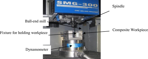
The milling process carried out on a vertical computer numerically controlled milling machine (SMG-300) equipped with a maximum spindle speed of 5,000 rpm, and a 5 mm HSS ball-end mill, shown in Figure . The setup of machining process and the milled surfaces is shown in Figures and , respectively. The mechanical properties of CFRP has been given in Table .
Table 1. Mechanical properties of CFRP
2.2. Measurement of machining force
The machining force (Fw) in milling process consists of three orthogonal components: Fx, Fy, and Fz. The value of machining force is calculated according to the following equation:(1)
(1)
In order to measure the machining force, the workpiece was mounted on a Kistler 9272 (Switzerland) equipped with four component piezoelectric dynamometer (see Figure ). Data acquisitions were made through piezoelectric dynamometer, and using RS-232C protocol, data were transferred to the PC, and then data were monitored by the software DynoWare type 2825 A Kistler®.
2.3. Measurement of surface roughness
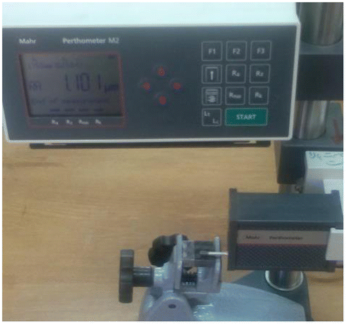
Surface roughness of machined slots, represented by the parameter Ra, was measured by PERTHOMETER M2 (Mahr, Germany) instrument. The cut-off and traversing length values were 0.8 and 5.5 mm, respectively. For each test, three measurements were executed over milled surface, and then results were averaged. The surface roughness measurement tool used is shown in Figure .
2.4. Design of experiment
To model the process by RSM, implementation of experimental tests is required to find the relationship between responses and independent variables. Moreover, in order to minimize the cost of experimental work, minimizing the number of experimental tests is required to obtain the optimum condition. In this current study, 27 tests based on full factorial design, three level for any variable, were conducted. Table shows the levels of variables.
Table 2. Levels of variables
By conducting the tests on the carbon fiber-reinforced epoxy composite (CFRP), using HSS ball-end mill, the influence of independent variables such as spindle speed (N), feed rate (f), and depth of cut (CD) on the responses such as machining force (Fw) and surface roughness can be found. Twenty-seven experimental tests based on full factorial design were done, and the results are shown in Table .
Table 3. Obtained data from experiments for modeling of machining process
2.5. Modeling of process with RSM
A response surface is an analytical function such as a polynomial that relates the behavior of one or more response variables to several independent variables.
Response surface methodology (RSM) has many applications in design, development, and optimization. An important step in response surface modeling is to define an appropriate approximation for the actual relationship between the response and the set of independent variables.
Usually a first-order polynomial model, which is the simplest model, is used. To employ the linear regression model for the true response surface, it can be written as;(2)
(2)
The parameters bj, j = 0, 1, … , K, are called the regression coefficients. The equation can also be expressed in matrix notation as;(3)
(3)
In general, y is an n × 1 vector of the observations, x is an n × p matrix of the levels of the independent variables, b is a p × 1 vector of the regression coefficients, and ε is an n × 1 vector of random errors.
Thus, the least-squares estimator of b is:(4)
(4)
The fitted regression model is:(5)
(5)
In scalar notation, the fitted model is:(6)
(6)
A quadratic linear regression model was used to predict the responses dependent on spindle speed (N), feed rate (f), and depth of cut (DC).(7)
(7)
Two response variables are machining force (Fw) and surface roughness (Ra), and three independent variables are spindle speed (N), feed rate (f), and depth of cut (DC). The functions which relate the responses to independent variables will be obtained by RSM, and the obtained functions can be optimized by PSO.
Based on data in Table , the fitted linear models, obtained from RSM, are described as follow:(8)
(8)
(9)
(9)
In order to find the error of RSM, some experimental data were compared with obtained data from the model (Equations 8 and 9) and are shown in Table . The data in Table show that the RSM model is in good agreement with experimental data approximately.
Table 4. Comparison of RSM predictions with experimental data
2.6. Particle swarm optimization
In PSO algorithm, each single solution is a “particle.” All particles have fitness values evaluated by the fitness function to be optimized, and have velocities, which direct the flying of the particles. The particles are flown through the problem space by following the current optimum particles. PSO is initialized with a group of random particles (solutions) and then searches for optimal by updating generations. In one iteration, each particle is updated by following two best values. The first one is the best solution (fitness) achieved so far. Another best value tracked by the particle swarm optimizer, is the best value, obtained, so far, by any particle in the population (global best position); so, the velocity and position of the obtained optimum solution (particle) are updated during the iterative process. The stop criteria reach the maximum iteration number or satisfaction of the minimum error condition.
Suppose that the search space is n dimensional, the particle of the swarm can be represented by an n dimensional vector , and the velocity of this particle can be represented by n dimensional vector
, where S is the search space. The fitness of each particle can be evaluated according to the objective function of the optimization problem.
is the last best position of the particle “i,” noted as its individual best position. The global best position is Pg(t) and the new velocity of particle will be assigned according to the following equations:
(10)
(10)
where c1 and c2 are acceleration parameters, ω represents the inertia weight which decreases linearly from 1 to near 0 while training, and r1 and r2 are random numbers ranging between 0 and 1. The velocities of the particles on each dimension are clamped to a maximum velocity: Vmax. The new position of the particle “i” is calculated by the following equation:(11)
(11)
2.7. Constraint-handling technique for the PSO
Most practical engineering optimization problems are actually aimed at determination of the global optimum with respect to the fact that some certain functions, such as constraining functions, must not exceed their critical values. As a matter of fact, the constraining functions apportion the entire seeking area into separate islands. In the recent decades, various techniques have been proposed to handle these constraining functions. An acceptable solution defines a new fitness function, F(x), to be optimized. F(x) illustrates the combination of the objective function, f(x), and weighted RSM terms. And Pi(x), i = 1, 2, … , N defined as penalty values for the violation of each constraining function (Deb, Citation2000):(12)
(12)
where wi (i = 1, 2, … , N) are predefined values.
3. Optimization
Optimization of objective function in most of the classic methods of optimization has a certain sequence of calculations. These methods consider a point of the search space, and improve among most of the ascending or descending areas gradually. This point-to-point way creates the sucking basic problem in a local optimum point. The simplest way to get a better local answer is that optimization from different initial points, which have been selected randomly, be repeated, so other answers can be investigated and be compared. However, for the problems which have many variables, the possibility of the lack of access to global minimum is high.
Today, new methods of optimization, as efficient tools, have been proposed which are used in solving many optimization problems for searching the global minimum. These algorithms such as PSO are inspired by observations of natural phenomena.
3.1. Objective and constraints
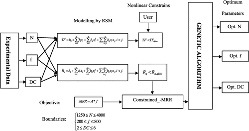
The main goal of this paper is to determine the optimal machining parameters leading to maximum material removal rate under machining force and surface roughness constraints. In this regard, the milling process is defined in the standard optimization problem format which can be solved by a numerical optimization PSO algorithm. PSO algorithm requires objective and constraining functions. In view of the constrained optimization, a new fitness function, Constrained_−MRR (the minus sign indicates finding the maximum of MRR in optimization process), is to be optimized. Constrained_−MRR illustrates the combination of the objective function MRR and weighted RSM terms, Pi(x), defined as penalty values for the violation of the constraining functions (machining force and surface roughness). In a case study, the maximum allowable thrust force and surface roughness, 50 N and 1 μm, have been selected, respectively, as the constraints of the model for high accuracy of the finishing process, which has been requested by the customer.
Figure depicts the flowchart of this method. Two RSM models are employed in modeling of machining force and surface roughness. The material removal rate constitutes the main function for the PSO, and machining force and surface roughness were applied to the input function of PSO. In the each iteration, PSO calculates the −MRR result with the constraints and satisfies them.(13)
(13)
where D is the diameter hole and f is feed rate. A is the area of tool cross section and is defined as follows:(14)
(14)
where r is the radius of the tool and it is 2.5 mm.
4. Results and discussion
4.1. Influence of the machining parameters on the machining force
Due to the inhomogeneity and anisotropic properties of CFRPs, the interaction between the CFRPs and the cutting tools is very distinguishably different from the interaction at tool–workpiece interfaces during metal cutting processes. The investigation of chip formation and material removal mechanisms in CFRP machining provides the essential knowledge to understand the interaction between CFRPs and tools along with providing insights into the development of cutting theories. Although mechanistic modeling techniques have been exploited in the recent years, a satisfactory model with the capability of predicting the cutting forces for arbitrary cutting conditions under the entire range of fiber orientations is still absent (Che, Saxsena, Han, Guo, & Ehmann, Citation2014).
The curves of machining force versus feed rate for various spindle speeds have been shown in Figure for depth of cuts 2, 6, and 8 mm. According to these curves, the machining force increases with feed rates and decreases with spindle speed. From comparison of three curves, it can be seen that increasing the depth of cut increases the machining force.
Figure 6. Machining force versus feed rate for various spindle speeds; (a) DC = 2 mm, (b) DC = 6 mm, and (c) DC = 8 mm.
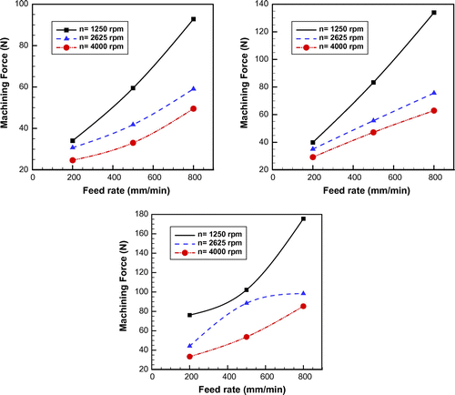
It is reported that an increase in feed rate and cutting speed steadily increases the temperature in the cutting zone (Sreejith, Krishnamurthy, Malhurta, & Narayanasamy, Citation2000). Similar effects of the cutting speed on temperature rise at the cutting edge in GFRP cutting were found (Sakuma & Seto, Citation1981). So by increasing the temperature, due to increase in cutting speed, the cutting force is decreased.
It is distinguished that the chip formation of FRPs which is commonly associated with plowing (i.e. deformation), cutting (i.e. shearing), and cracking (e.g. rupture, delamination, fracture, and buckling), from homogeneous metals associated with plastic deformation and shearing (Sreejith et al., Citation2000).
Thus, optimum condition for machining force obtained in low depth of cut and feed rate and high spindle speed. According to Table , the effective factor on machining force is feed rate.
4.2. Influence of the machining parameters on the surface roughness
Figure shows the evolution of surface roughness versus feed rate for the different spindle speed values. According to these figures, it can be realized that surface roughness increases with feed rate, and decreases with spindle speed. In addition, it can be recognized by comparison of Figure (a–c) that the depth of cut has no clear and considerable effect on surface roughness.
Figure 7. Surface roughness versus feed rate for various spindle speeds; (a) DC = 2 mm, (b) DC = 6 mm, and (c) DC = 8 mm.
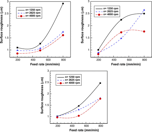
It is reported that theoretical surface roughness is decreased with the decrease in feed rate and the increase in nose radius. Theoretical surface roughness is as Ra = 0.0321f2/r. The surface roughness is affected by the tool material and tool geometry, but is not affected by the depth of cut. This is because the plastics in the GFRP have good machinability, but the glass fiber is difficult to cut because of its brittleness. It is noted that the surface roughness does not change much with increase in cutting speed. This result is very different from that for ordinary metal cutting (Lee, Citation2001).
4.3. Analysis of variance
The obtained values of machining force (Fw) and surface roughness (Ra) were used to determine the significant factors which affect the milling process. The significant parameters influencing the machining force and surface roughness were found using the ANOVA procedure. The ANOVA for cutting force and surface roughness has been shown in Tables and , respectively. The last column indicates the percentage of contribution of each factor to the total variation, indicating the degree of influence on the results. It is can be concluded that feed rate is the most effective factor on machining force (40.48%) and surface roughness (64.73%). Depth of cut has minimal effect on machining force (18.95%) and surface roughness (2.86%). It can be seen in Tables and that the interaction of N × f, N × DC, and f × DC have little effect on surface roughness and machining force.
Table 5. ANOVA for machining force
Table 6. ANOVA for surface roughness
4.4. Optimization by PSO
The Fortran 90 code was conducted to solve the constrained optimization problem in Equation 13. The parameters of the PSO algorithm have remarkable effects on the quality and effectiveness of the algorithm. To obtain the best parameters, several codes with different parameters were run. The results indicate that if the linear weight (ω) decreases linearly from 0.9 to 0.02, c1 and c2 be equal to 2.25, the number of particles in each subspace is 40, and the maximum and minimum velocity values are 4 and −4, respectively; and therefore, better results are obtained.
The optimum condition for constrained optimization problem, obtained from PSO algorithm, is presented in Table and compared with experimental results. Approximately, a good agreement is observed between predicted values and obtained values from experimental measurements. This indicates that RSM coupled by constrained PSO can be an effective optimization tool to obviate the need for either development of an analytical model or estimation of an empirical expression.
Table 7. Results of validation test
5. Conclusion
This paper presents a methodology for constrained optimization of CFRPs manufactured by RTM technology. Based on the experimental results, the following conclusion can be drawn:
The maximum machining force (175.5 N) was achieved in N = 1,250 rpm, f = 800 mm/min, DC = 6 mm, and maximum surface roughness (2.917 μm) was achieved in N = 1,250 rpm, f = 800 mm/min, and DC = 2 mm. The minimum machining force (24.6 N) in N = 4,000 rpm, f = 200 mm/min, DC = 2 mm, and minimum surface roughness (0.829 μm) was achieved in N = 4,000 rpm, f = 200 mm/min, and DC = 4 mm.
The ANOVA for machining force and surface roughness showed that feed rate is the most significant factor.
The results of coupled PSO and RSM model in finding the maximum of constrained material removal rate (minimum of −MRR) had a good agreement with experimental results. Thus, it can be concluded that RSM-coupled PSO is an effective tool to find the optimum machining condition in a constrained optimization.
Additional information
Funding
Notes on contributors
Hamzeh Shahrajabian
Hamzeh Shahrajabian, is an assistant professor in the Department of Engineering, Islamic Azad University, Najafabad Branch, Isfahan, Iran. In 2014 he received his PhD degree in mechanical engineering -manufacturing in university of Birjand, Iran. He received his MS degrees from Birjand University. His research areas cover polymer nanocomposites, sandwich composites forming and machining.
References
- Che, D., Saxena, I., Han, P., Guo, P., & Ehmann, K. F. (2014). Machining of Carbon fiber reinforced plastics/polymers: A literature review. Journal of Manufacturing Science and Engineering, 136, 1–22.
- Davim, J. P., & Reis, P. (2005). Damage and dimensional precision on milling carbon fiber-reinforced plastics using design experiments. Journal of Materials Processing Technology, 160, 160–167.10.1016/j.jmatprotec.2004.06.003
- Davim, J. P., Reis, P., & António, C. C. (2004). A study on milling of glass fiber reinforced plastics manufactured by hand-lay up using statistical analysis (ANOVA). Composite Structures, 64, 493–500.10.1016/j.compstruct.2003.09.054
- Deb, K. (2000). An efficient constraint handling method for genetic algorithms. Computer Methods in Applied Mechanics and Engineering, 186, 311–338.10.1016/S0045-7825(99)00389-8
- El-Sonbaty, I., Khashaba, U. A., & Machaly, T. (2004). Factors affecting the machinability of GFR/epoxy composites. Composite Structures, 63, 329–338.10.1016/S0263-8223(03)00181-8
- Farahnakian, M., Razfar, M. R., Moghri, M., & Asadnia, M. (2011). The selection of milling parameters by the PSO-based neural network modeling method. The International Journal of Advanced Manufacturing Technology, 57, 49–60.10.1007/s00170-011-3262-1
- Guo, W., Li, W., Zhang, Q., Wang, L., Wu, Q., & Ren, H. (2014). Biogeography-based particle swarm optimization with fuzzy elitism and its applications to constrained engineering problems. Engineering Optimization, 46, 1465–1484.10.1080/0305215X.2013.854349
- Jahanmir, S., Ramulu, M., & Koshy, P. (2000). Machining of ceramics and composites (pp. 267–293). New York, NY: Marcel Dekker.
- Lee, E.-S. (2001). Precision machining of glass fibre reinforced plastics with respect to tool characteristics. The International Journal of Advanced Manufacturing Technology, 17, 791–798.10.1007/s001700170105
- Palanikumar, K. (2008). Application of Taguchi and response surface methodologies for surface roughness in machining glass fiber reinforced plastics by PCD tooling. The International Journal of Advanced Manufacturing Technology, 36, 19–27.10.1007/s00170-006-0811-0
- Ramulu, M., Arola, D., & Colligan, K. (1994). Preliminary investigation of effects on the surface integrity of fibre reinforced plastics. Engineering Systems Design and Analysis ASME, 64, 93–101.
- Ratnaweera, A., Halgamuge, S. K., & Watson, H. C. (2004). Self-organizing hierarchical particle swarm optimizer with time-varying acceleration coefficients. IEEE Transactions on Evolutionary Computation, 8, 240–255.10.1109/TEVC.2004.826071
- Razfar, M. R., & Zadeh, M. R. (2009). Optimum damage and surface roughness prediction in end milling glass fibre-reinforced plastics, using neural network and genetic algorithm. Proceedings of the Institution of Mechanical Engineers, Part B: Journal of Engineering Manufacture, 223, 653–664.10.1243/09544054JEM1409
- Sakuma, K., & Seto, M. (1981). Tool wear in cutting glass-fiber-reinforced-plastics: The relation between cutting temperature and tool wear. Bulletin of JSME, 24, 748–755.10.1299/jsme1958.24.748
- Santhanakrishnan, G., Krishnamurthy, R., & Malhotra, S. K. (1988). Machinability characteristics of fibre reinforced plastics composites. Journal of Mechanical Working Technology, 17, 195–204.10.1016/0378-3804(88)90021-6
- Smith, W. F. (1990). Principles of materials science and engineering (pp. 699–724). New York, NY: McGraw-Hill.
- Sreejith, P. S., Krishnamurthy, R., Malhotra, S. K., & Narayanasamy, K. (2000). Evaluation of PCD tool performance during machining of carbon/phenolic ablative composites. Journal of Materials Processing Technology, 104, 53–58.10.1016/S0924-0136(00)00549-5
- Wang, F. F., & Su, Ch. T. (2014). Enhanced fuzzy-connective-based hierarchical aggregation network using particle swarm optimization. Engineering Optimization, 46, 1501–1519.10.1080/0305215X.2013.846335
- Yoon, H. S., Wu, R., Lee, T. M., & Ahn, S. H. (2011). Geometric optimization of micro drills using Taguchi methods and response surface methodology. International Journal of Precision Engineering and Manufacturing, 12, 871–875.10.1007/s12541-011-0116-6
- Yu, J., Wang, S., & Xi, L. (2008). Evolving artificial neural networks using an improved PSO and DPSO. Neurocomputing, 71, 1054–1060.10.1016/j.neucom.2007.10.013


