 ?Mathematical formulae have been encoded as MathML and are displayed in this HTML version using MathJax in order to improve their display. Uncheck the box to turn MathJax off. This feature requires Javascript. Click on a formula to zoom.
Abstract
The modified relay feedback test (MRFT), which was recently proposed as a continuous oscillation method for identification of the process parameters and controller tuning, is used for the design of a robust and an adaptive Proportional-Integral (PI) controller for a gas loop in the oil–gas separator. The gas normally found in the separator is the natural gas (mostly methane) which is contained in crude oil coming from the reservoir. The robust and adaptive PI controllers are developed from analysis of 64 operating modes corresponding to certain ranges of the gas inflow and liquid-level values. It is shown through the developed model and simulations that these operating modes have significant effect on the dynamics of the gas loop. Dynamic properties of the process in each mode are studied through MRFT. The controllers are designed in order to maintain the pressure during the change of the operating conditions. Performance of the designed control system is studied by simulations.
Public Interest Statement
In oil production, when the fluids from the oil reservoir reach the surface, they usually contain a mixture of gas, oil, and water. The first surface production step is to separate oil from gas and water that come from the wells, which is done by separators. Control of separators is important to the quality of oil and gas produced. A method of controller tuning for the gas pressure control in a separator is presented in the research. The approach proposed involves the modified relay feedback test. Two different approaches to controller design, robust and adaptive, are developed.
1. Introduction
Controller tuning methodology based on continuous cycling can be traced back to the closed-loop Ziegler–Nichols (Z–N) method (Citation1942). This method involves the excitation of continuous oscillation of the process variable. Recently, a few other continuous cycling tests were proposed (Boiko, Citation2008; Hang, Astom, & Wang, Citation2002; Kaya & Atherton, Citation2001; Majhi & Atherton, Citation1999; Wang, Lee, & Lin, Citation2003; Yu, Citation1998, Citation1999). Probably, the best-known test of this type is the Åström–Hägglund’s (Citation1984) relay feedback test (RFT). It is worth noting that this test leads to the same ultimate gain and ultimate frequency as Z–N test if the model of the oscillations is based on the describing function (DF) method (Atherton, Citation1975).
In RFT, the excitation of the oscillations always occurs at the frequency ωn corresponding to −180° of the phase response of the process. However, it is known that the controller introduction in such system would change the frequency ωn, so that the frequencies of the test oscillations and the phase crossover frequency of the open-loop system are different. The modified relay feedback test (MRFT), that introduced a coordinated selection of test parameters and tuning rules, was proposed by Boiko (Citation2012) to eliminate the noted drawback of RFT. The MRFT can be considered as a further logical development of the ideas used in the Ziegler–Nichols and Åström–Hägglund tests. The approach proposed in MRFT was also termed as the holistic approach to the test and tuning. The main advantage of this test is that it can provide the desired value of the gain or phase margin exactly in non-parametric tuning (under the assumption that the DF method provides an exact model). In the present research, we aim to design a tuning procedure for the PID controller of the pressure loop of the oil–gas separator, using MRFT.
In oil production, when the fluids from the oil reservoir reach the surface, they usually contain a mixture of gas, oil, and water. The first surface production step is to separate oil from gas and water that comes from the wells, which is done by separators. The separation process involves equilibrium considerations or phase changes of these components. The equilibrium separation is done by four basic mechanisms as listed below (Roussean, Citation1987):
Gravity separation which depends mainly on the density differences of the fluid components (water, crude oil, and associated gas) and occurs by reducing the velocity of a stream so that terminal velocity of particles due to gravity exceeds the velocity of bulk flow.
Centrifugal force is similar to gravity separation, but it uses geometrical effects and dispersed phase concentrations for high-speed mechanical separation.
Separation by impaction where the fluid will deflect around the body, while the particle having greater inertia will impact the body allowing the opportunity for separation.
Electrically induced charge separation to attract the particles using fixed bodies such as plates with an opposite electrical charge.
We will further consider only gravity separators. There are two designs available: horizontal and the vertical separators, which are suitable to separate the fluids in oil and gas production facilities using the gravity separation techniques. The horizontal type is used when the amount of liquid is higher than the amount of gas, while the vertical type is used in the opposite case.
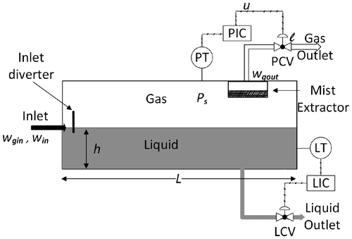
The horizontal-type liquid–gas separator is shown in Figure and works as follows. First, the fluids flow into the separator and hit an inlet diverter, causing a sudden change in momentum. The initial separation of liquid and vapor occurs at the inlet diameter. The gravity force causes the liquid droplets which have a higher density to fall out of the gas stream (with a lower density) to the bottom of the vessel, where it is collected. Then, the liquid leaves the vessel through the level control valve (LCV). The gas passes through a mist extractor that removes very small droplets of liquid which are not easily separated by the gravity force (Roussean, Citation1987). The separation process is accomplished in one or more stages of decreasing pressure. There exist an optimum number of the stages required to separate the fluids. However, increasing the number of stages would normally increase the cost: due to necessity of additional separator, piping, controls, and space. According to Stewart and Arnold (Citation2009), only one initial separation stage is necessary for the considered industrial case study, as the pressure of the gas in the plant is maintained at around 80 PSIG. Due to the relatively low pressure of fluid coming to the separator and the low water content (around 7%), the horizontal-type two-phase separator is used for initial separation within the considered platform production facilities.
In the considered case study, the separator is a horizontal-type two-phase separator. The gas is separated from the liquid with the gas and liquid being discharged. The gas is coming with crude oil from the wells. The separated gas is supplied to another plant for further treatment and use as a fuel gas for the gas turbine and high-pressure pumps. The separated oil is pumped to the storage and sales facilities. Therefore, two different loops are used to control the liquid and the gas in the vessel.
The model of the gas loop is considered as the process in this system which is to be controlled by the Proportional-Integral (PI) controller. The aim of the PI controller is to maintain the pressure equal to the set point despite various disturbances coming from the inflow stream and the gas pressure manifold. Maintaining the pressure equal to the set point is important not only to protect the vessel from the over-pressurization. When the separator pressure grows above the set-point of 80 PSIG, depressurization has to be done by sending the gas to flaring, which leads to a negative environmental impact. Thus, a pressure controller with a good performance is necessary for this application.
Conventional control used in the separator gas pressure loop is a PI control (Liptak, Citation2005), which also agrees with authors’ industrial experience. To the best of the authors’ knowledge, there are no publications suggesting other controls. This probably happens due to the fact that the basic model of the process (without actuator-valve model), which can be found in Sayda and Taylor (Citation2007), can be written as a linear first-order differential equation. If a control is designed for this model only, then any proportional control with sufficiently high gain would reveal excellent performance. This design and model would not, however, match the reality: the actuator-valve dynamics has a significant effect on overall pressure loop dynamics, and cannot be neglected. A new model that involves all main contributors to the gas loop dynamics, such as gas-phase dynamics, valve dynamics, and gas flow between the separator and the gas manifold, is developed in the present paper.
This paper is organized as follows. First, the process model of the separator gas pressure is developed on the basis of the conservation laws. The models of the actuator and valve are presented too. Then MRFT is described. After that, a Simulink model of the industrial separator considered in the case study is introduced; MRFT is performed on this model; and with PI, optimal tuning rules optimized through ITAE criterion for the pressure loop are obtained. The robust and adaptive controllers are designed involving 64 operating modes. Finally, the simulation results showing performance of the system are presented and analyzed.
2. Process model
As shown in Figure , the typical industrial liquid–gas separator has two outlets to be controlled. The gas loop controls the gas outlet, where the pressure controller with indicating function (PIC) compares the set point with the process variable (gas pressure) which is measured by the pressure transmitter. The PIC sends the control signal (command) to the pressure control valve to operate accordingly. The level loop controls the liquid level in the separator where the level controller with indicating function senses the change in the liquid level and controls the LCV accordingly. In order to design the model that represents the gas pressure loop for the separator, the following equations of gas pressure process given by Figure are considered. The ideal gas law is used to represent gas pressure in the vessel:(1)
(1)
where ps is the gas pressure inside the separator which is the process variable to be controlled, Vg is the volume of the gas in the separator, R is the universal gas constant, T1 is the temperature of fluid inside the separator μ is the molecular weight, mg is the mass of the gas.
The difference between the total volume of the vessel and the volume of crude oil is equal to the volume of the natural gas inside the vessel, which is given by the following equation:(2)
(2)
where Vmax is the total volume of the vessel, L is the length of the vessel, and Ao is the part of the vertical cross-sectional area of the vessel filled with crude oil.
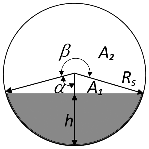
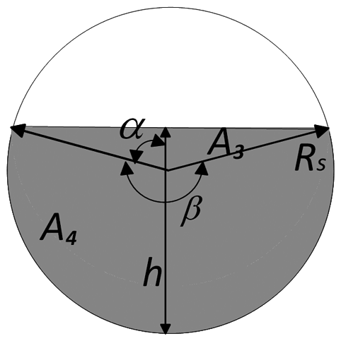
There are two cases for the cross-sectional area of crude oil which depends on the ratio between the level of the crude oil and the separator radius Rs:
Case 1: the level of the crude oil is less than or equal to the radius of the separator h ≤ Rs (Figure ).
The cross-sectional area of crude oil is computed as the difference between the circle area, the area of the triangle A1, and the area of the sector A2:(3)
(3)
where:
Then,
Case 2: the level of the crude oil is higher than the radius of the separator: h > Rs (Figure ).
The cross-sectional area of crude oil for Case 2 is computed as the sum of the triangle area A3 and of the sector area A4:(4)
(4)
where:
As shown in Figure , the separator has inlet and outlet lines (pipes). The control valve, installed in the outlet line, controls the gas outflow. The inlet flow is uncontrolled and acts as a disturbance applied to the system. The pressure process has also relation with rate of change for the mass of gas as given by the following mass balance equation:(5)
(5)
where wgin and wgout are the mass gas flow rates for the inlet and the outlet of the separator.
The outlet mass gas flow rate from the separator through the control valve is given by the St. Venant and Wantzel’s equation (Beater, Citation2007):(6)
(6)
where Cd is the discharge coefficient. is the flow function given by:
is the critical pressure ratio, Av is the function characterizing valve orifice pass area which related to the valve travel (
),
for the linear control valve (such as the globe valve), Pcin is the discharge or manifold pressure of the control valve, Rspec is the specific gas constant of the methane, and
is the isometric constant of methane.
The PI controller has the following equation:(7)
(7)
where Kc is the proportional gain, Ti is the integral time constant, rp is the set point pressure of the PI controller.
Finally, the relation between the valve travel and the controller commands is represented by the first-order plus dead time model (Boiko, Citation2013; Sayedain & Boiko, Citation2011):(8)
(8)
where is the dead time, Tv is the time constant, and kv is the valve gain.
3. MRFT and holistic test and tuning
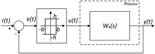
The MRFT is used in this research as a method of controller tuning for the pressure loop. The test signal that it generates (through the feedback principle) is similar to the one of a relay controller, which is discontinuous. The control output u(t) of the MRFT is given as follows by Boiko (Citation2012):(9)
(9)
where h is the amplitude of the relay, b1 = ßemax, b2 = −ßemin, emin < 0, emax > 0 are the last “singular” point of the error sinusoid signal corresponding to the last maximum and minimum values of e(t) after crossing the zero level, ß is a parameter of MRFT and of the tuning rules, and is the control value at the time immediately preceding the current time t (Boiko, Citation2013).
The system under MRFT can be represented by the block diagram (Figure ), in which, however, relay hysteresis value b is not constant but variable—as defined above. Process model under the test is shown in Figure in either the state space form or as the transfer function Wp(s).
3.1. Describing function of MRFT
The DF method is applied in Boiko (Citation2012) to analyze the periodic motion that occurs during the test. MRFT acts as hysteretic relay, in a sense, with unknown value of the hysteresis though. The DF of the hysteretic relay having hysteresis value b is given by (Atherton, Citation1975):(10)
(10)
where a is the amplitude of the input sinusoidal signal.
But the system has unknown hysteretic value, which depends on the amplitude value: b = ßa. Therefore, the DF formula can be written as follows (Boiko, Citation2012):
The following harmonic balance equation can be used to find the parameters of oscillations during the MRFT.(11)
(11)
where a0 and Ω0 are the amplitude and the frequency of the periodic motions.
MRFT allows for the exact design of the gain margin (assuming that the DF method provides an exact model). Since the amplitude of the oscillation a0 is measured from the test, the process gain at frequency Ω0 can be obtained as follows:
(12)
(12)
which after introduction of the controller becomes the process gain at the critical frequency.
3.2. MRFT optimal design and tuning
For a gas pressure process, from the point of view of possible parameter variation, it is important to find the gain margin of the system (Boiko, Citation2013). It was shown in Boiko (Citation2013) that if the tuning rules have the format of:
for the proportional gain,
for the integral time constant, and
for the derivative time constant,
and the following equality constraint is satisfied:(13)
(13)
where γm is the required gain margin, and the designed controller will provide the desired gain margin exactly. To provide specified gain margin, MRFT must be carried out with parameter:
Yet, there is an issue of optimal combination of the coefficients that define tuning rules because there is only one Equation 13 and three variables. Optimal values of the PID parameters could be found by applying the tuning rules and optimization methods.
Among the optimization criteria, the most suitable are criteria that are measured from the output response of the system to the step change. The use of criteria that depend on the time domain rather than the frequency domain is preferred (Boiko, Citation2013). Therefore, the following popular time domain criteria can be used.
Integral absolute error (IAE):
Integral time absolute error (ITAE):(14)
(14)
where t is the time and e(t) is the error.
4. Separator model and controller design
The Matlab and Simulink are used to simulate the system dynamics. The process and equipment data related to each part were collected in order to build the model of the process. Control valve data sheets were used to identify the actuator-valve characteristic and to calculate the required parameters: Av Cd = 0.0054921 m2, with the dynamic model being . The initial conditions of the model values are calculated such as the outlet gas pressure from the valve, gas mass, and inlet gas flow rate. It is considered that the control valve is linear and can open from 0 to 100% so that
. The total volume of the two-phase separator is 100 m3. However, the level of the liquid is specified by two limiting values, and the gas volume can be found from Equation 2. Gas properties such as the density, molar mass, and specific gas constant are those of methane, as it is the main ingredient of the gas contained in the separator, with 78% from the gas content.
From Equation 1, by considering the constant volume of gas (we disregard the dynamics of volume change because it is slow and addresses the variable volume in a quasi-static manner), the pressure rate of change:
The modes of operation that affect the dynamics of the gas loop depend on the level and gas inflow for the separator, where
Level of the liquid in the separator:
L ∈ [515 mm, 1825 mm]
Gas inflow to the separator:
win ∈ [2.73 kg/s, 9.92 kg/s]
We split the above ranges of level and gas inflow into seven segments each and consider (7 + 1) × (7 + 1) = 64 operating modes of the separator in the controller design. The MRFT technique is applied for the 64 modes of operation. The model is run in Matlab-Simulink; first, the MRFT method is applied for each mode individually, and the critical amplitude au and critical frequency Ωu are calculated and presented in Table . The MRFT is carried out in the incremental way described in Boiko (Citation2013), so that the produced control is the increment to the control value is a steady state corresponding to a certain operating mode. The tuning of the controller parameters is done by specifying the gain margin of three using the optimal tuning rules for gas pressure loops given in Boiko (Citation2013), as the values of the constants used in the tuning rules: c1 = 0.331, c2 = 0.216, and the parameter of MRFT β = 0.132. Gain margin of three is considered a good option for providing “moderately fast” closed-loop response—as per Boiko (Citation2013). From Table , the parameters kc and Ti for each mode are calculated using the tuning rules and are shown in Table . It can be noted that the value of the kc is very small since our control variable (gas pressure) is in Pascal as per SI standards.
Table 1. The critical amplitude au (×102) and critical frequency Ωu of the system
Table 2. The parameters Kc (×10−5) and Ti for gain margin 3
4.1. Robust controller
From Table , the robust controller can be designed by choosing the parameters Kc and Ti that provide the least aggressive action and, therefore, will be suitable for all modes. In this design, the performance of the control system is guaranteed regardless of changes in the plant dynamics. However, none of the modes provides a combination of lowest gain and highest time constant. The robust controller values are selected from Table at the point of (1.451 m, 2.73 kg/s), which provides the highest value of 9.485 for Ti and sufficiently low value of Kc being 1.1 × 10⁻⁵. The overall performance is then verified by simulations.
4.2. Adaptive controller
Another method of approaching the issue of variable parameters of the process is the use of a controller having variable parameters. This approach constitutes the adaptive control. In using this approach, we utilize the data of Table to design a gain schedule for the controller. Table serves as a look-up table for finding the controller gain for a given mode, which is characterized by L and win. This approach is straightforward but inconvenient in realization, as it requires storing look-up tables and using interpolation. A more convenient way would be to obtain a suitable approximation for the values of Table as functions of L and win.
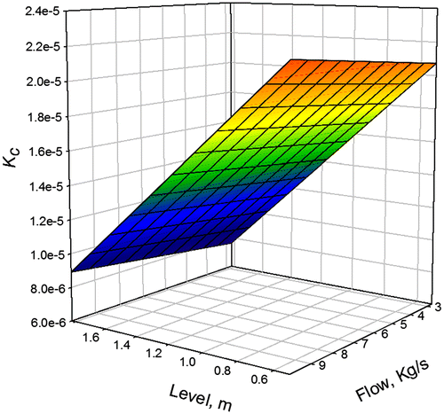
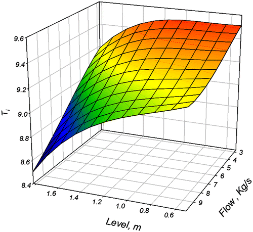
The 3D graphs for the proportional gain Kc and integral time constant Ti as functions of L and win are given in Figures and , respectively. One can notice that the dependence of Kc on L and win is nearly linear, so that linear approximation would be appropriate. The dependence of Ti on L and win has more complex character, which requires higher order approximations. Both approximating functions were found through minimization of mean square error technique. The dependence of Kc on L and win is given by:
. And the approximating dependence of Ti on L and win is given by third-order surface as follows:
5. Simulation
The dynamics of the system with the robust and adaptive (gain scheduled) controllers was tested by the Matlab simulations under two different operating modes which are the normal (inflow rate wgin = 6.3 kg/s and level h = 1.17 m) and the “minimum” (inflow rate wgin = 2.73 kg/s and level h = 0.515 m) operating modes. The Simulink diagram of the system is presented in Figure . Simulation is done using the fourth-order Runge–Kutta algorithm with the step size of 0.01s. Representative testing results are shown in Figures –. The trends show the pressure loop performance under the simultaneous action of the gas inflow and level and step change of these disturbances, and the manifold pressure and the pressure set point. The performance of the robust PI controller is demonstrated by the loop reaction to the disturbances and set point combinations, which is a sinusoidal change of the inflow and level with a step change of the separator pressure set point (Figures , , , , , , , , , and ). The performance of the adaptive PI controller is demonstrated by the loop reaction to the three disturbances and set point change, which are the sinusoidal changes of the inflow and level and a step change of the separator pressure set point, the inflow and level and the manifold pressure (Figures , , , , , , , , , and ). IAE index values for the step tests are presented in Table . IAE index was selected as a metric because it was the basis for the development of the tuning rules in Boiko (Citation2013) that are used in this research. One can see from the trends of the separator pressure in Figures –, and Table that the performance of the robust controller is slightly higher, which is revealed as smaller pressure fluctuations. Also, the trends of the separator pressure with adaptive controller in Figures and are shifted down which means that during the simultaneous action of the gas inflow and level, the separator pressure with adaptive controller does not go to high value as with the use of the robust controller in Figures and . One of the main objectives to design the gas loop controller was to protect the vessel from overpressurization. As mention earlier, when the separator pressure grows above the set point of 80 PSIG, depressurization has to be done by sending the gas to flaring, which leads to a negative environmental impact. Therefore, a pressure controller with a good performance is highly recommended in this case. Thus, the choice of the adaptive PI controller over the robust controller is preferred.
Figure 8. Separator pressure (solid line) and sinusoidal inflow change (dashed line) with robust PI controller.
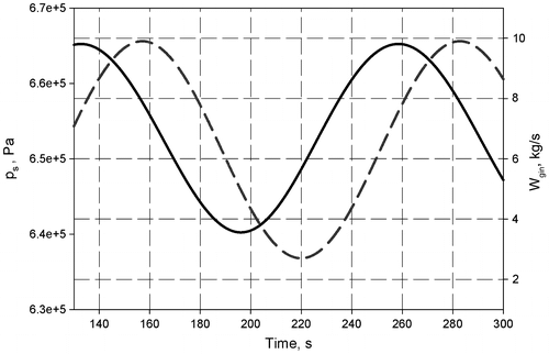
Figure 9. Separator pressure (solid line) and sinusoidal inflow change (dashed line) with adaptive PI controller.
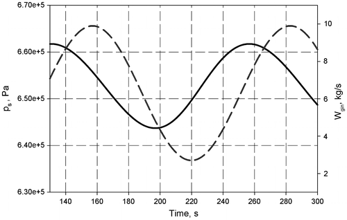
Figure 10. Separator pressure (solid line) and sinusoidal level change (dashed line) with robust PI controller.
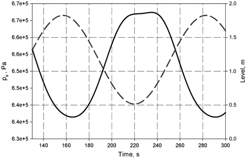
Figure 11. Separator pressure (solid line) and sinusoidal level change (dashed line) with adaptive PI controller.
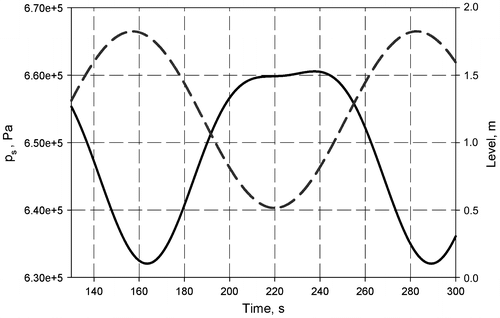
Figure 12. Separator pressure (solid line) and step down change of manifold pressure (dashed line) for robust PI controller; in normal mode.
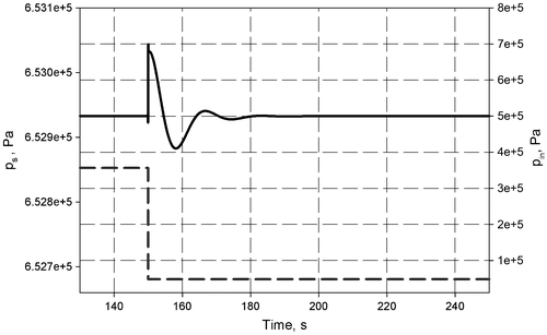
Figure 13. Separator pressure (solid line) and step down change of manifold pressure (dashed line) with adaptive PI controller; in normal mode.
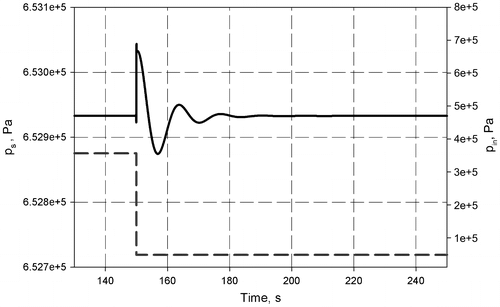
Figure 14. Separator pressure (solid line) and step down change of set-point pressure (dashed line) with robust PI controller; in normal mode.
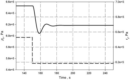
Figure 15. Separator pressure (solid line) and step down change of set-point pressure (dashed line) with adaptive PI controller; in normal mode.
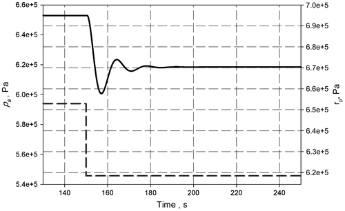
Figure 16. Separator pressure (solid line) and step down inflow change (dashed line) with robust PI controller.
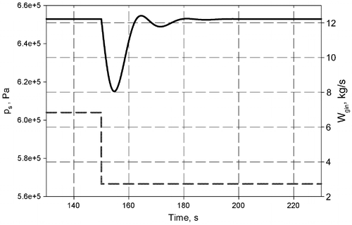
Figure 17. Separator pressure (solid line) and step down inflow change (dashed line) with adaptive PI controller.
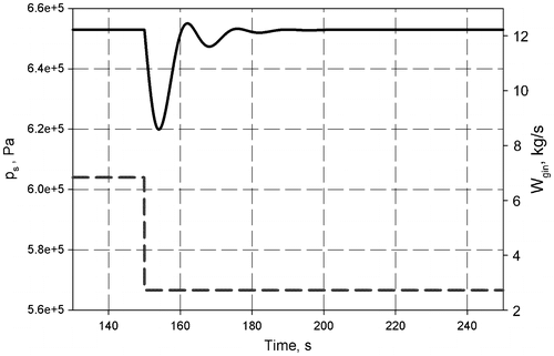
Figure 18. Separator pressure (solid line) and step up change of inflow (dashed line) with robust PI controller.
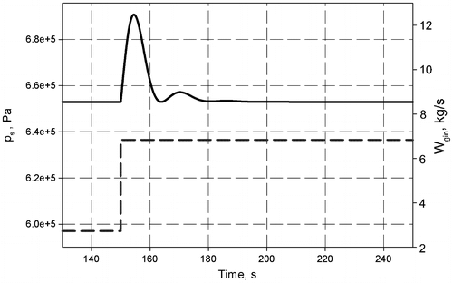
Figure 19. Separator pressure (solid line) and step up change of inflow (dashed line) with adaptive PI controller.
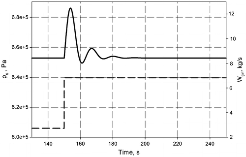
Figure 20. Separator pressure (solid line) and step up change of set-point pressure (dashed line) with robust PI controller; in the normal mode.
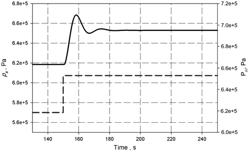
Figure 21. Separator pressure (solid line) and step up change of set-point pressure (dashed line) with adaptive PI controller; in the normal mode.
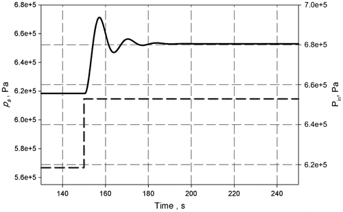
Figure 22. Separator pressure (solid line) and step down change of manifold pressure (dashed line) with robust PI controller in the “minimum” mode.
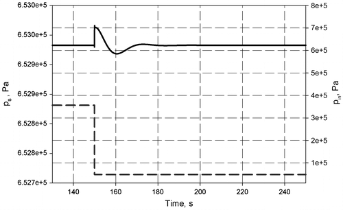
Figure 23. Separator pressure (solid line) and step change of manifold pressure (dashed line) with adaptive PI controller in the “minimum” mode.
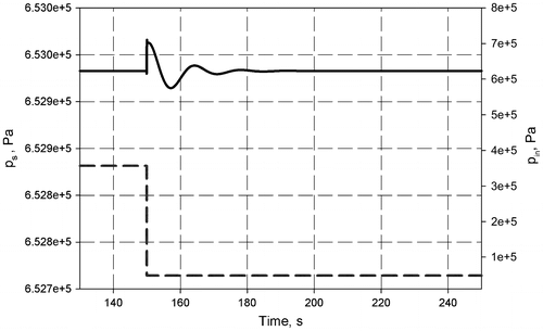
Figure 24. Separator pressure (solid line) and step down inflow change (dashed line) with robust PI controller in the “minimum” mode.
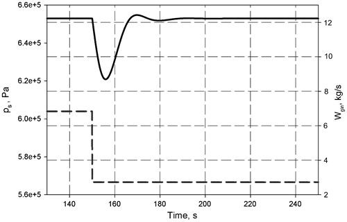
Figure 25. Separator pressure (solid line) and step down inflow change (dashed line) with adaptive PI controller in the “minimum” mode.
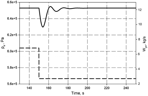
Figure 26. Separator pressure (solid line) and step down change of set-point pressure (dashed line) with robust controller in the “minimum” mode.
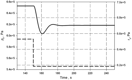
Figure 27. Separator pressure (solid line) pressure and step down change of set-point pressure (dashed line) with adaptive controller in the “minimum” mode.
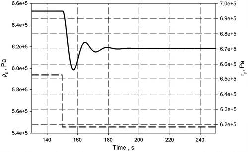
Table 3. IAE indices for step response
6. Conclusions
Oil–gas separators are widely spread in the oil industry. As per authors’ observations, gas pressure controllers often suffer poor performance due to operating mode change because once tuned in a certain operating mode, they may reveal either too-aggressive or too-sluggish closed-loop behavior in other operating modes. In the present research, a nonlinear model of the separator, which considers multiple operating modes, is presented. On the basis of MRFT, characterization of the process dynamics in various operating modes is proposed. This characterization allows one to use relatively simple methods of linear systems controller design and ensures overall stability through either conservative or gain scheduling strategies.
Respectively, two different approaches to the controller design/tuning are proposed: robust and adaptive. Methodology of realization of each of them is developed. Matlab/Simulink model of the system is developed. It is shown through simulations that both approaches are valid, with the robust approach being simple, whereas the adaptive approach providing higher performance.
Additional information
Funding
Notes on contributors
Igor Boiko
Hamdati Al Shehhi is a process control engineer at ZADCO, Abu Dhabi and a part-time MSc student at the Petroleum Institute, Abu Dhabi. Igor Boiko (PhD, DSc) is a professor at the Electrical Engineering department of the Petroleum Institute, Abu Dhabi. He leads a group that conducts research in the areas of industrial control applications and control theory. He authored monographs “Discontinuous control systems” (2009) and “Non-parametric tuning of PID controllers” (2013), many journal and conference publications. The group currently conducts research in process-control areas related to oil and gas production, separation, and treatment, as well as theoretical research in PID tuning, discontinuous and sliding-mode control.
References
- Åström, K., & Hägglund, T. (1984). Automatic tuning of simple regulators with specifications on phase and amplitude margins. Automatica, 20, 645–651.10.1016/0005-1098(84)90014-1
- Atherton, D. P. (1975). Nonlinear control engineering-describing function analysis and design. Workingham: Van Nostrand.
- Beater, P. (2007). Pneumatic drives. Berlin: Springer-Verlag.10.1007/978-3-540-69471-7
- Boiko, I. (2008). Autotune identification via the locus of a perturbed relay system approach. IEEE Transactions on Control Systems Technology, 16, 182–185.10.1109/TCST.2007.903108
- Boiko, I. (2012). Loop tuning with specification on gain and phase margins via modified second-order sliding mode control algorithm. International Journal of Systems Science, 43, 97–104.10.1080/00207721003790344
- Boiko, I. (2013). Non-parametric tuning of PID controllers: A modified relay-feedback-test approach. London: Springer-Verlag.10.1007/978-1-4471-4465-6
- Hang, C., Astrom, K. J., & Wang, Q. G. (2002). Relay feedback auto-tuning of process controllers—A tutorial review. Journal of Process Control, 12, 143–162.10.1016/S0959-1524(01)00025-7
- Kaya, I., & Atherton, D. P. (2001). Parameter estimation from relay autotuning with asymmetric limit cycle data. Journal of Process Control, 11, 429–439.
- Liptak, B. G. (2005). Instrument engineers’ handbook (Vol. 2). CRC Press.
- Majhi, S., & Atherton, D. P. (1999). Autotuning and controller design for processes with small time delays. IEE Proceedings D, 146, 415–425.
- Minorsky, N. (1992). Directional stability of automatically steered bodies. Journal of the American Society of Naval Engineers Inc, 34, 280–309.
- Roussean, R. (1987). Phase segregation. In L. J. Jr., Jacobs, & W. Roy (Eds.), Handbook of separation process technology (pp. 129–190). New York, NY: Wiley.
- Sayda, A. F., Taylor, J. H. (2007). Modeling and control of three-phase gravity separators in oil production facilities. In Proceedings of 2007 American Control Conference, Orlando, FL, USA.
- Sayedain, S., Boiko, I. (2011). Optimal PI tuning rules for flow loop, based on modified relay feedback test. In Proceedings of 2011 IEEE Conference on decision and control, Orlando, FL, USA.
- Stewart, M., & Arnold, K. (2009). Gas–liquid and liquid–liquid separators. Oxford: Elsevier.
- Wang, Q., Lee, T. H., & Lin, C. (2003). Relay feedback. London: Springer.10.1007/978-1-4471-0041-6
- Yu, C. (1998). Use of saturation relay feedback in PID control. US Patent No. 5742503.
- Yu, C. (1999). Automatic tuning of PID controllers: Relay feedback approach. New York, NY: Springer.
- Ziegler, J. G., & Nichols, N. B. (1942). Optimum settings for automatic controllers. Transactions of the American Society of Mechanical Engineers, 64, 759–768.

