
 ?Mathematical formulae have been encoded as MathML and are displayed in this HTML version using MathJax in order to improve their display. Uncheck the box to turn MathJax off. This feature requires Javascript. Click on a formula to zoom.
Abstract
The growing use of multiprocessing systems has given rise to the necessity for modeling, verifying, and evaluating their performance in order to fully exploit hardware. The Petri net (PN) formalism is a suitable tool for modeling parallel systems due to its basic characteristics, such as parallelism and synchronization. In addition, the PN formalism allows the incorporation of more details of the real system into the model. Examples of such details include contention for shared resources (like memory) or identification of blocked processes (a definition for blocked processes is found in the Introduction section). In this paper, PNs are considered as a modeling framework to verify and study the performance of parallel pipelined communications. The main strength of the pipelines is that if organized in a proper way, they lead to overlapping of computation, communication, and read/write costs that incur in parallel communications. Most of the well-known pipelined schemes have been evaluated by theoretical analysis, queueing networks, and simulations. Usually, the factors taken into account are scheduling, message classification, and buffer spacing. To the best of our knowledge, there is no work in the literature that uses PN as a modeling tool for verification of the pipeline-based scheme. Apart from verification, a more accurate and complete model should also consider other factors, such as contentions and blocked processes. These factors have a high impact on the performance of a parallel system. The PN model presented in this paper accurately captures the behavior of the pipeline-based parallel communication system. The model considers synchronization, message scheduling, and message classification, while it is proven to be free of deadlocks and contentions. Also, the model is characterized by symmetry, so it can be used for large and complex systems.
Public Interest Statement
This paper presents a Petri net-based model used to verify and evaluate the performance of pipelined parallel distributions. It precisely captures the behavior of a pipeline-based parallel communication system. The model considers message scheduling and message classification, while it is deadlock and contention free. Because it is symmetric, it can easily be used for larger systems only with minor changes.
The model is composed of two subnetworks: the reading subnetwork and the pipeline execution subnetwork. The reading subnetwork implements the task of preparing the necessary pipeline tasks. The pipeline execution subnetwork implements the actual communication by executing the series of tasks. The model (and thus the real system) maintains its safety by preventing a pipeline from starting until all pipeline tasks have been formed. Also, it avoids deadlocks by preventing a new communication to start before all the other segments have been assigned the proper tasks.
1. Introduction-related work
The problem of data distribution between several processors is very important, affecting the efficiency of parallel algorithms. As a parallel program is being executed, it may require a different distribution of data between the processors or redistribution.
The principal issues that need to be considered to model a pipeline-based communication are (1) total redistribution cost, (2) message scheduling, (3) message classification, (4) load balancing, (5) contentions, and (6) blocked processes.
| (1) | Total redistribution cost: It is the total cost to redistribute data between several processors. It is composed of the index computation overhead, the total communication overhead, and the R/W (or I/O) overhead. The index computation overhead refers to computing the target processor and the memory positions where each data element will be located. The total communication overhead incurs during data distribution between parallel processors. The R/W overhead refers to the time consumed by R/W operations. | ||||
| (2) | Message scheduling: The term refers to the organization of message exchanges into structured communication steps, such that the total redistribution cost is minimized. | ||||
| (3) | Message classification: The term refers to dividing the data to be redistributed into homogeneous (in terms of communication cost) groups to effectively organize their redistribution. | ||||
| (4) | Load balancing: The ability of having all communication links equally or nearly equally loaded to avoid network congestions. | ||||
| (5) | Contention: This refers to conflicting transferring processes that distribute data to the same target processor at the same time. | ||||
| (6) | Blocked processes: A process is blocked if it waits for the execution of another process that never occurs. | ||||
Table 1. Pipeline-based communication models in the literature and the factors they incorporate
In Kashif et al. (Citation2013), the worst-case response times of real-time applications on multiprocessor systems are computed. The proposed technique schedules a simple pipelined communication operation for data distribution. The model consists of a set of processing resources interconnected with pipelined communication resources (CRs). Data transmitted on the CRs travel through the first segment followed by the next, and so on. Simultaneous transmission of data on segments is allowed. This means that while data are being transmitted on a later segment, new data can be transmitted on an earlier segment in parallel. However, if this situation is not handled carefully, it can lead to blocked processes. Pipeline segments should be carefully released first, before handling new transmissions.
The work in Kuntraruk et al. (Citation2005) addresses the problem of developing a resource estimation model for applications executed within a parallel pipeline model of execution. The model estimates the computation and communication complexities for parallel pipelined applications. It includes two components: the ones that execute pipelined application tasks and the ones that perform merge operations. In the beginning, there are tasks processed on
processors, one task per processor. Afterwards, at every step, the tasks are reduced in half since half of the processors are merging data received from the previous step. The model pays no attention to conflicts that could easily arise when different data volumes are carried over the network of processors. Also, there is no concern about possible blocked processes.
An interesting approach for modeling pipeline parallelism is given in Navarro et al. (Citation2009). The authors develop a series of analytical models based on queueing theory for several parallel pipeline templates, which are modeled as closed or open queueing systems. Specifically, each pipeline segment is treated as a queue (for closed systems) or as a
queue (for open systems). The models assure load balancing over the network. Since the proposed models are based on queues, contention is not avoided between messages that try to enter the queue. Things deteriorate if there is not much space in the queues. Necessarily, these models (unlike most of the models described) have to take into account the limited memory (buffer space). Simulations on real systems were used to verify that the queuing pipeline models capture the behavior of parallel systems faithfully. A related approach in Ties et al. (Citation2007) marks the pipeline segments and tries to track the data communications performed in each of them. Also, an open system approach model is proposed by Liao et al. (Citation2004), with the same factors taken into account. The latest approaches mentioned do not guarantee load balancing between processor sets.
Many other pipeline-based parallel communication models have been presented in the literature (King et al., Citation1990; Preud’homme et al., Citation2012; Rodrigues et al., Citation2008; Zhang & Deng, Citation2002). Generally, the models presented are basically concerned with maintaining some load balancing on the network during the pipelined distributions, with little or no attention paid on the problem of contentions and blocked processes. All these models also use simulation as the verification and performance study tool. Table summarizes the factors addressed by the pipeline communication models discussed in this section. Note that all of the models involve some communication scheduling and load balancing (the messages distributed are of the same size) and none of them considers blocked processes. Also, most of the models assume that buffer space is enough to handle the distributed data and do not include a straightforward contention-preventing mechanism.
This paper introduces a Petri net (PN) model for modeling and simulating pipelined and deadlock-free parallel communications. PNs are used to examine the sequence of executed tasks (Granda, Drake, & Gregorio, Citation1992). The study of the process sequence is very important to avoid faults such as deadlocks [(some very general ideas about modeling pipelined parallel communication with PN can be found in Zhao, Liu, Dou, and Yang (Citation2012)]. A deadlock-free scheme enhances the performance of any communication system. Generally, deadlocks occur when processes stay blocked for ever (waiting for an event caused by another process that never occurs) and in such cases, probably the whole system needs to be restarted. A block cyclic redistribution scheme can suffer from deadlock situations since each target block is formed during runtime and after a series of interrelated processes, which are described in Section 4.
The rest of the paper is organized as follows: Section 2 presents the background of the model, which is based on block cyclic() to block cyclic(
) distributions. Section 3 describes the pipelined communication, which is modeled via PN in Section 4. Section 5 presents some simulations for the complete PN model of Section 5, for three different communication scenarios. Section 6 concludes this paper.
2. Background
The model presented in this work has it is mathematical background on the well-known block cyclic redistribution problem, so this section briefly introduces the definitions required.
Definition 1
Data array is an array of size used to represent the redistributed data. An array element is an element of the redistributed data indexed with
. Indexing begins from zero, thus,
.
Definition 2
A processor grid can be represented by a two-dimensional (2D) table called communication grid :
. Obviously,
is the source processor index,
is the destination processor index, while
represent the total number of sending and receiving processors, respectively.
Definition 3
Data distributed in a block cyclic fashion are divided into data blocks. If each data block has r elements, then, provided that divides
, the data array will be divided into
blocks where:
. If
does not divide
, then
. We use variable
as a block index that relates data blocks to the processors of the communication grid in a cyclic manner. Therefore,
lies in
or
(since
). Finally, variable
indexes the local position of an element inside a block. This means that
.
Definition 4
The source distribution is the mapping of a data array element with index
to a processor index
, a block index
, and a local position inside the block
, where
.
Definition 5
Consider an element that is distributed cyclic(s) on processors. The number of blocks created is
, where
is the block size. Variable
relates data blocks to the processors and its bounds are found in the interval
or
(because
). The target distribution
is defined similarly to the source redistribution. Parameters
have the same meaning as
of the source distribution. We can derive an equation for the distribution of element
:
.
Table 2. Definitions of variables in this paper
Definition 6
Suppose that data are a redistributed array from cyclic() on
processors to cyclic(
) on
processors. In this case, changes will occur for all elements as far as their processor, block, and local position indices are concerned. These changes are described by:
or:
(1)
(1)
This linear Diophantine equation is subject to the following restrictions: ,
,
, where
is the least common multiplier of
, that is,
.
Definition 7
The cost of transferring a message from a sending processor to a receiving processor
is called communication cost,
. To compute the communication cost for a processor pair
, one needs to find the number of quadruples
that satisfy Equation 1, given the number of sending
and receiving
processors, and the block sizes of the source
, and the target
redistribution.
Definition 8
Consider the following function:(2)
(2)
where is the greatest common divisor of
and
. A pair of processors
belongs to a communication class (Desprez, Dongarra, Petitet, Randriamaro, & Robert, Citation1998a)
if:
(3)
(3)
As Equation 3 indicates, all pairs of processors that communicate belong to a class of . The number of existing classes is at most
. Table summarizes the variables used in this paper.
3. Pipelined communication
This section presents the pipelined interprocessor communication. Each pipeline includes a number of tasks responsible for the communication between carefully selected processor pairs. The main properties of the pipeline operations and their tasks are:
| (1) | Each pipeline task handles the transmission of data between processor pairs that have the same communication cost. | ||||
| (2) | A pipeline operation cannot include more than one task that handles message transmissions of a cost. | ||||
| (3) | The time required for the execution of a task equals the communication cost of the processor pairs it includes. | ||||
| (4) | The time required for the execution of a pipeline operation equals the execution time of its longest task. | ||||
| (5) | All tasks are scheduled in such a way that receiving processors get one message at a time, thus congestions on the receiving ports are avoided. | ||||
| (6) | The pipeline will include a number of segments (the role of segments in the communication will be explained in Section 3.3) equal to the number of different costs that exist in the scheme. | ||||
| (7) | The time the processors remain idle is minimized. | ||||
3.1. Stage 1: Generating the pipeline tasks
The pipeline tasks must be scheduled in such a way that receiving processors get one message at a time. To satisfy this requirement, each task must include a number of distributions of same cost to different destination processors. Therefore, classes are used to group all the communicating processor pairs with respect to the cost of such communication. A processor pair lies in class , if
mod
. The class processor table (CPT) shows the class of each processor pair and the communication cost of this class. Consider a redistribution with
, and
. In this case,
. The CPT for this redistribution example is shown in Table . For example, if
, then
. Thus,
mod
= 1 mod 9 = 1. This means that the processor pair (4,3) belongs to the class
. The cost of communication for each class is computed as the number of quadruples
that satisfy Equation 1, for a given set
.
Table 3. CPT for
Having defined the classes, it remains to: (1) find the number of pipeline operations and the number of their tasks, (2) define an upper bound for the number of processor pairs selected from each class for a pipeline task, and (3) define the number of classes from which the processor pairs are selected to have a minimum of transmissions (one message for each destination processor) in each pipelined communication.
To minimize the time the processors remain idle, each pipeline must be scheduled to have a maximum number of tasks; in other words, to transfer as much data as possible with a single pipeline operation. If the number of different communication costs found in all classes is , then a pipeline operation has at most
tasks and can satisfy up to
message transmissions, without contentions.
Theorem 1 (for proof see Desprez et al., Citation1998a) is used to define an upper bound for the number of processor pairs in class that will be added in a pipeline task. Initially, we set
and
. Since
divides
and
divides
, there exist integers
and
such that:
and
. Also, we set
gcd
.
Theorem 1
Each class includes exactly processor pairs. Theorem 1 leads to the following corollaries:
| (1) | The number of sending requests to a destination inside a class is | ||||
| (2) | There are exactly | ||||
Proposition 1
For a pipeline operation with minimum number of communications, the communicating processor pairs must be selected from
different classes.
The minimum number of message exchanges for a pipeline operation corresponds to “one message for each destination processor”, that is, messages in total. A pipeline task can satisfy at most
communications from one class, otherwise contentions will occur. From the relationship
, one can easily conclude that the processor pairs must be selected from
classes to complete
transmissions. The generation of the pipeline operations and their tasks can be described in a series of well-defined steps as follows:
Step 1: Solve (Equation 3) for all processor pairs to define the processor classes and create the CPT.
Step 2: Find the total communication cost for each by computing the number of quadruples
that satisfy Equation 1. Since each class includes messages of the same cost, only one computation is needed for a pair
. All other processor pairs in the same class would have the same cost. Afterwards, define the value of different costs that exist for this distribution,
.
Step 3: Start from the class , for which the communication cost
is minimum, and get
processor pairs. If the pairs selected from
can form a task of
transmissions, that is, if
=
, move to Step 4. Otherwise, check if there is a class of the same cost as
to add up to
pairs. In either case, the processor pairs that task
should include must be such that all destination processor indices differ:
=
, where
.
Step 4: Find the class with the next communication cost and repeat Step 3. Tasks with the same communication cost are not allowed in the same pipeline operation. Once a pipeline includes
message exchanges, it is completed. Go to Step 5.
Step 5: Check the value of to find the number of different costs for the rest of the processor pairs and use Steps 3 and 4 to create the next pipeline operation.
Step 6: When all processor pairs are added in a pipeline operation, terminate, if not, return to Step 1. Consider the redistribution for =
=9,
=4, and
=5. In this case,
. The CPT is shown in Table . Also (see the last column of Table ),
since there are four different communication costs in the scheme varying from 1 to 4 time units. According to Step 3, we get
processor pairs from
class to create a task of
transmissions. We can select pairs from any of the two classes
and
since they have the same communication cost of one time unit. Suppose that we select from class
. These processor pairs will form the first task
of the first pipeline operation.
According to Step 4, the processor pairs of class cannot be used in any of the tasks for this pipeline because the same communication cost of one unit will appear twice for all destinations. For the same reason, the classes
and
,
and
, and
and
are mutually exclusive. The tasks of the first pipeline include processor pairs from
,
,
, and
. In Step 5, the value of
is checked to find the number of different costs in the remaining classes
,
,
, and
. We have
. Therefore, Steps 3 and 4 are used to create the second pipeline (the two pipeline operations are shown in Table ).
Table 4. Pipeline operations and its tasks for
Once the pipeline operations and their tasks are scheduled, the messages must be read from local processor memories and prepared for distribution. This stage is described in the next section.
3.2. Initialization—reading messages from memory
This stage involves computing the local memory positions where the data to be distributed reside. Using the terms of Table and Equation 1, one can describe the reading stage as follows: the reading stage computes the local positions of the data elements to be redistributed. These elements reside in block
of the source processors’
memory. All this information can be easily obtained when (Equation 1) is solved. As an example, consider the transfer of data blocks towards processor
in a redistribution problem with parameters
. Table gives solutions of equation (Equation 1) when
and
.
Table 5. Solutions of Eq.1 for
Suppose that we want to know the position of the data elements scheduled to be distributed from source processor to target processor
. As shown in Table , these elements reside in block
and their local position inside the block is defined by
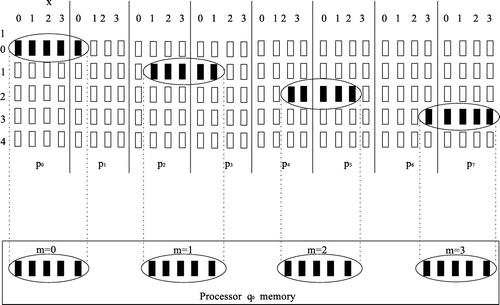
, that is, 0, 1, 2, and 3. The upper part of Figure shows all the elements that will move to
and their initial position in the source processors. These positions are computed from Equation 1, as shown in Table . Once the initialization computations are done, the pipelines are ready for execution.
Figure 1. Reading from source processors’ memories and writing to target processors’ memories.
3.3. Transferring the messages and writing to the target processors’ memory
When the pipelines execute, they generate a number of communications between several processors. It is important to note that pipeline operations are executed sequentially (one after the other) but their tasks are parallel. Figure shows the execution of the two pipeline operations for the redistribution with parameters . Each pipeline operation is composed of four tasks (
).
Figure 2. R/W for .
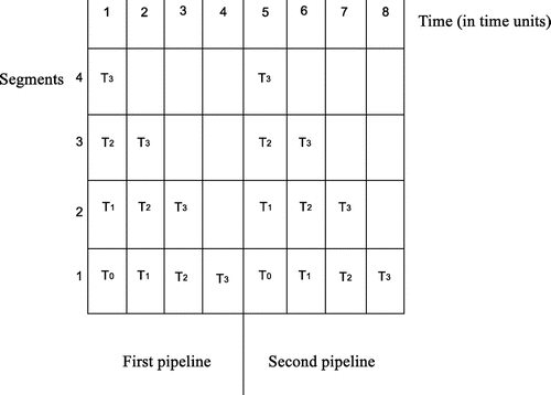
The horizontal axis displays the time in time units, while the vertical axis gives the pipeline segment. The role of a segment is to handle the distribution process performed by a pipeline task . When a task is handled by the
th out of
segments, it is scheduled to be the
th to complete its distribution job. For example, in Figure , there are four segments that handle four transferring tasks. As tasks move “downwards” from segment 4 to segment 1, they are approaching their completion. Apparently, in this figure,
is to finish first, as it is the “cheapest” task (one time unit, see Table ). The time required for the execution of a task equals the communication cost of the processor pairs it includes. From the previous discussion in Section 3.1, it is obvious that the pipeline tasks are completed at different times. Since each task cannot contain more than a message to a specific destination, contentions at the receiving processors’ ports are avoided. To make it more clear, consider the four tasks shown in Table . All tasks handle messages to the same target nodes; however, congestions are avoided since these tasks complete at different times.
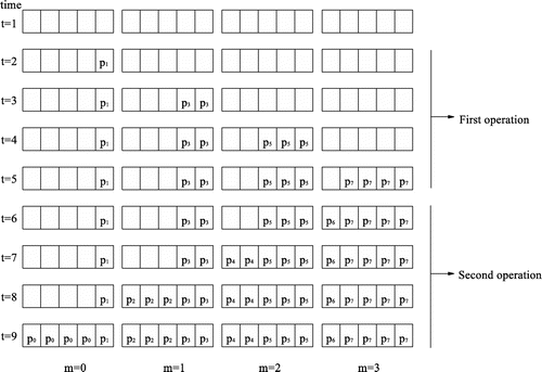
Each of the tasks performs a partial transferring job, that is, it “adds” elements to data blocks at a certain time. Now, let us examine how these task are executed during communication to processor . Suppose that communication starts at time
. By the end of time
, the first task
is complete (see Figure ). This means that one element from source
(note in Table that
sends data to
during execution of
) is transferred to its new location. By the end of time time
two more elements are added from
. The first pipeline operation completes at
time units. In the very same manner, the second pipeline operation starts execution at time
. At each time unit, a task completes and adds elements to
. At
, the distribution to
is complete. Similarly, all destination processors receive their data blocks during the same period of time.
When pipeline execution completes, the distributed elements become parts of newly formed blocks indexed by in the memories of the target processors
. Their new local position inside the blocks is defined by
. For example, the lower part of Figure shows the newly formed blocks in the memory of
. It is clear that each new block has five elements. The block
is formed by four elements transferred from
and one element transferred from
. The local position of these five data elements in the newly formed block is given by
, that is, 0, 1, 2, 3 (for elements from
), and 4 (for the one element from
). The lower part of Figure shows the new position of the elements distributed to
in their new blocks
and 3. Figure shows the formulation of these blocks over time, during the execution of the pipeline tasks included in the two pipeline operations shown in Table . Assuming that communication starts at time
, at
, the first task will be completed. Therefore, the target processor
will have received one data block from the sending processor
(see task
of the first pipeline in Table ). According to the results in Table , for
, this block will be stored in position
of the target block
(recall that block positions indexes start from 0, so this element occupies the last position of the block). Similarly, at
, task 2 is completed. Therefore, the target processor
will have received two data blocks from the sending processor
(see task
of the first pipeline in Table ). According to the results in Table , for
, this block will be stored in positions
and
of the target block
.
Figure 3. Memory writing over time for .
4. The PN pipelined communication model
As described in Section 2, the pipeline based models of communication in the literature do not consider the problem of deadlocks (blocked processes), while they seldom take into account the contentions. The goal here is twofold: (1) use the PN model as a tool to verify that the communication model of Section 3 is deadlock and conflict-free and (2) obtain the performance metrics for three different distribution scenarios from the PN model via a discrete event simulations.
The system model under consideration comprises of a number of pipeline tasks in a single pipeline operation that execute as described in Sections 3.1–3.3. Apparently, a distribution problem can include a variable number of operations with a variable number of tasks. Since all pipeline operations can follow the same pattern (execute a number of parallel tasks), it is important to design a symmetric model, so that it can be applied for variable number of tasks with minor changes. From a modeling perspective, there are three occurrences of interest: (1) generation of the pipeline tasks, (2) execution of the pipelines, and (3) handling the pipeline segments. This section presents a fully symmetric PN model for these occurrences and performs deadlock and safeness analyses to verify that the models (and consequently the pipeline communication schedule) do not suffer from blocked processes or contentions. Notice that occurrences (2) and (3) are closely related, thus presented in the same subsection. Before that some preliminaries regarding PN are required.
4.1. PN preliminaries
This subsection briefly presents the basic PN notations required in this work. A PN is a set of two different types of nodes: places (pictured with circles) and transitions (pictured with bars). Places and transitions are connected via directed arcs from places to transitions and vice versa. If an arc is directed from node to node
, then
is an input to
. The state of a PN changes when it is executed. The execution is controlled by the tokens placed inside nodes. When the PN is executed, a number of tokens are removed from their current place and are located in different places. The distribution of tokens in the places defines the state of the net. This distribution is referred as marking of the PN. Apparently, when a system is initialized, it must have an initial state or initial marking. In this paper, every marking (initial or later) is denoted by
, where
is the marking index (
denotes the initial marking),
is the number of places, and
is every place that has a token in this marking.
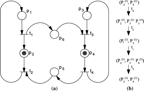
Figure 4. (a) A PN example and (b) Reachability tree
A change of a PN’s state (that is, the movement of tokens) occurs when the transitions are enabled to fire and this is true when all of its input places have a token. To describe that fact that a transition’s firing changed the marking from to
, the following notation is used:
or
, where
indicates the new set of token-holding places. As an example, consider the PN of Figure (a). The initial marking is
and the only enabled transition is
(
is not enabled, although
has a token because its input place
has no token). When
fires, the token will be removed from
and two new tokens will be placed, one in
and one in
, resulting in
.
A very important issue about PN is that a sequence of firings can result in a marking , where no transition is enabled. This would drive the model in a deadlock (process being blocked by another process). This means that there are a number of unwanted states that can lead to a deadlock. Spotting these states is a very important issue when modeling because it uncovers the sequence of executing events that can lead the model, and consequently the real system, to deadlock. The tool used to analyze the PN model for deadlocks is called reachability tree. A reachability tree is a set of nodes that represents all possible markings of a net (if the set is finite) caused by the firing of transitions. Figure (b) shows the reachability tree for the example of Figure (b). The transition that causes every new marking is written near the arrows. The parentheses above places
show the number of tokens in every place. If no parentheses are included, the number of tokens is 1. In the case of Figure (b), no place does store more than one token, but this is not always the case.
Peterson (Citation1997) introduced two basic rules for the reachability analysis: (1) if a newly formed marking is equal to an existing one on the path from the root (which is an initial marking) to this new marking, then this marking is a terminal node. This means that if a new marking is equal to a previous one, then all markings reachable from it are already added to the reachability tree, and (2) if a newly formed marking is greater than a previous marking
, then all possible firings from marking
are also possible from marking
. In this case, the components of
which are greater than the corresponding components of
are replaced by the symbol
, where
is a value arbitrarily large compared to a natural number
. Also, the sequence of firings that lead from
to
can be repeated endlessly, resulting every time in an increase of the number of tokens in the corresponding positions
. The symbol
is used to denote an arbitrarily large number of tokens in
, and the notation
is used. From Peterson’s rules, we derive Proposition 2 that gives a condition under which a model does not reach a deadlock.
Proposition 2
A PN model will never reach a deadlock if for all markings that are roots to subtrees formed on the reachability tree, it is possible to find a terminal node or a marking greater than the root.
In a PN model, the places represent conditions, while the transitions represent events. The presence of a token in a place shows that a condition is true. Since a condition is either true or false, there is no point in having more than a token in a place. Thus, especially when modeling hardware, one of the most important characteristic of PN is safety. A place of a PN is safe if its tokens are never more than one. In other words, therefore, safeness is violated when a sequence of firings puts two or more tokens in a place. In a parallel pipelined communication model, safeness ensures that there are no conflicting processes. Two or more processes are in conflict if, at the same time, they try to read the data blocks from the same source processors or to distribute and write data to the same target processors. The reachability analysis can show if multiple tokens are put in one place. Deadlock and safety analyses are provided for the proposed models in the next subsections.
4.2. Modeling the pipeline generation
The background and the steps required to generate the pipelines were presented in Section 3.1. Figure (a) presents the PN model and Figure (b) shows the pipeline generation in pseudo-code form. The part in the square is the reading subnetwork. Out of the reading subnetwork, there are two places, and
and two transitions,
and
, their roles described in the following. The places and transitions of the model are described as follows:
| Places | ||
| = | Generation request | |
| = | Transfer request (pipeline execution) | |
| = | Lowest cost class | |
| = |
| |
| = | While condition | |
| = | If condition | |
| = | Unread messages from lowest cost class | |
| = | End System available to generate new operation | |
| Transitions | ||
| = | Get lowest cost class | |
| = | Read | |
| = | Check condition | |
| = | Assign FALSE to condition | |
| = | Assign TRUE to condition | |
| = | Terminate reading | |
| = | Get to next lowest cost class | |
| = | Read unread messages from a same cost class | |
Figure 5. Pipeline generation model.
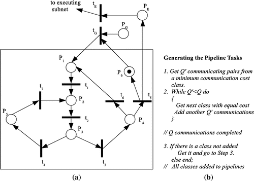
The pipeline generation of model of Figure is a repeating process which is initialized by a generation request provided that there is no pipeline generation in process. The initial marking, , indicates that the system is available to generate a new pipeline operation. Once
gets a token,
is enabled to fire and cause a series of firings. Firing of
will cause one token from
and one from
to be removed and one token to be placed to
(the lowest cost class is defined). This will produce
and enable
. Once
fires, a token is removed from
and one token is be placed to
(
messages generated). The new marking is
and
is enabled. Then, a while condition should be checked to decide if more messages are required from the same class. When
fires, a token is placed in
[marking
]. This enables two transitions (
), but only one can fire. It should be stressed that PN does not have a mechanism to decide which of the enabled transitions will fire. This depends on the designer of the model. When
is selected, there is a cyclic execution of firings, which repeats until
and creates repeatedly the markings
. When
is selected, a token is placed to
(marking
. As with the while condition, the system now has to check if there is a class of a specific cost not added. If so,
fires to cause
. This means that the sequence of firings described will be repeated. If not,
fires to cause
. This means that the system has terminated the pipeline generation and it is available to generate a new one. Also, a transfer request is activated (pipelines can be executed, as described in Section 4.3).
At this point, an anti-paradigm is necessary to stress the importance of modeling. Assume that the arc from to
is removed. Also, assume that a pipeline generation is in process (say, is checking the while statement, that is, a token is in
). If a second generation request is made, the system will have to start a new operation, starting with a new lower cost class. Thus, a token is placed in
. Then, a sequence of firings
will result in having two tokens stored in
. The system is not safe and it can start a pipeline generation with two different distribution parameters (lowest cost class). This is a conflict and the problem can be resolved only by restarting the system. To avoid this,
is enabled only if there is a request (token in
) and the system is available (token in
).
4.3. Execution of the pipelines handling the segments
Once the reading stage is completed, the actual communication can start. To execute the pipelined communication, the system control requires the following sequence of events:
Output of segment 1 (lowest segment that handles the lowest cost task) is ready. Thus, the lowest cost messages are to arrive at the target nodes.
Messages from segment 1 are written to the memories of the target nodes.
Output of segment 2 is ready. The task handled by segment 2 is now handled (“moves to”) by the lowest segment 1.
Segment 2 is free (ready to accept a task from the upper segment 3) and segment 1 now handles communication previously handled by segment 2 (these are the next messages to arrive to the target nodes).
Output of segment 3 is ready. The task handled by segment 3 moves to segment 2.
Segment 3 is free.
Output of segment 4 is ready. The task handled by segment 4 moves to segment 3.
The same pattern repeats until all
segments “move down” to segment 1 and complete communication.
| Places | ||
| = | Output of segment 1 is ready | |
| = | Segment 1 busy | |
| = | Segment 2 in segment 1 | |
| = | Lowest cost communication done | |
| = | Segment 2 empty | |
| = | Segment 3 in segment 2 | |
| = | Segment 2 output ready | |
| = | Segment 3 output ready | |
| = | Segment 4 in segment 3 | |
| = | Segment 3 empty | |
| = | Segment 4 empty | |
| = | Segment 4 output ready | |
| = | Segment | |
| = | Segment | |
| = | Lower segment communication continues | |
| Transitions | ||
| = | Unpack messages | |
| = | Write to receiving processors’ memory | |
| = | Reset segment 2 | |
| = | “Move” segment 2 to segment 1 | |
| = | “Move” segment 3 to segment 2 | |
| = | Reset segment 3 | |
| = | Reset segment 4 | |
| = | “Move” segment 4 to segment 3 | |
| = | “Move” segment 5 to segment 4 | |
| = | Reset segment 5 | |
| = | Reset segment | |
| = | “Move” segment | |
| = | Proceed communication in lower segment | |
Figure 6. Pipeline execution model.
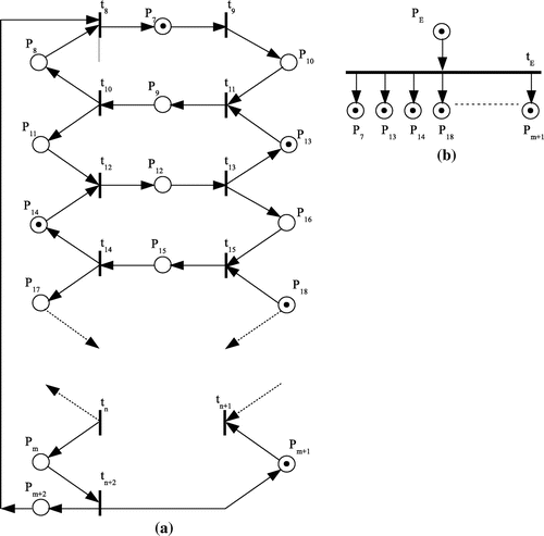
The proposed model is fully symmetric and it can be used easily for any number of states. Now, we are going to perform a test for the small distribution problem with parameters presented in Section 3. This test will help us understand fully the execution of the model. Based on the CPT (Table ), there are two pipeline operations, each including four tasks
(see Table ). The “movement” of these tasks across the pipeline segments is shown in Figure . The model for this distribution would include four circles formed by places and transitions and it is in shown in Figure (a).
Figure 7. Pipeline execution model for ,
.
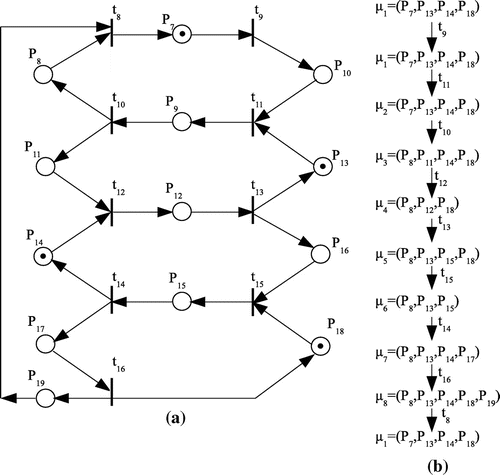
Initially, there are four places having a token, so . Thus, the only enabled transition is
. Once
fires, a token is removed from
and placed in
, resulting in
. From the real system’s point of view, this describes event completion of communications performed by task
(1) (
is handled by segment 1, see Figure ). Now,
is the only transition enabled. When it fires, it produces
(tokens are removed from
and one token is placed in
. In the real system event, task
is assigned to segment 1 (2) (because segment 2 moves to segment 1). Next, only transition
can fire, resulting in
. We have two events now: segment 2 is empty (3) and segment 1 is now busy with
(4). At this point, there is a synchronization issue: if
is enabled, the same pattern will be executed continuously. In the first of this series of executions, segment 1 will deliver some messages to the source processors, but afterwards there will be no messages to deliver because it will have to wait for tasks from segment 2 that do not come since segment 2 is empty waiting for upper segments. Practically, this means that the system stays idle for as long as this repeating execution continues and if this sequence does not change, the system reaches a deadlock and transmission has to start from scratch. Also, if
does not fire in the meantime, more than one token will be placed on
rendering the system unsafe. The solution we give with this model is to enable
only after
fires, which, for the real system, means that segment 1 can finish another distribution task only when all the remaining tasks are assigned to segments (“move downwards” as can be seen in Figure ). When
fires, a token is put in place
and this enables
. However,
can fire only after
, and
have fired, so all the tasks have been properly assigned to segments. That is, the model indicates that there must be a synchronization between segments (and consequently between the tasks they include) to avoid deadlocks.
Continuing the description, is the only enabled transition. Once it fires, it produces
. This indicates that event task
is assigned to segment 2 (5) (segment 3 moves to segment 2). Now,
is enabled. Once it fires, the new marking is
. Now, there are two events: output of segment 2 is ready (6) and segment 3 is empty (7). Event 6 means that
is ready to move to segment 1 after the completion of
executed there. From marking
, it is obvious that only
can fire, resulting in
. For the real system, event task
is assigned to segment 3 (8) (because segment 4 moves to segment 3). Now,
is enabled. When it fires, the new marking is
. The two real system events are: output of segment 3 is ready (9) (meaning that when
finishes from segment 1 and
is pushed from segment 2 to segment 1,
will move to segment 2) and segment 4 is empty(10). Now
is enabled. When it fires, the new marking is
. With a token in
, transition
is enabled again because all segments have moved as explained previously. When this firing occurs, there is one event: completion of communications performed by task
(11). Also, the new marking produced is
, meaning that the same sequence of firings repeats. Therefore, another transfer (task
) can be completed in the lowest segment 1 and the segments will move downwards again, repeating the same execution cycle. Next, the sequence of events produced by the model’s execution is listed (the events written boldfaced in the analysis above).
| (1) | Completion of communications performed by task | ||||
| (2) | Task | ||||
| (3) | Segment 2 is empty | ||||
| (4) | Segment 1 is now busy with | ||||
| (5) | Task | ||||
| (6) | Output of segment 2 is ready | ||||
| (7) | Segment 3 is empty | ||||
| (8) | Task | ||||
| (9) | Output of segment 3 is ready | ||||
| (10) | Segment 4 is empty | ||||
| (11) | Completion of communications performed by task | ||||
| (12) | Same pattern repeats | ||||
4.4. Advantages of the proposed model
At this point, it is important to summarize some of the advantages of the proposed model.
| (1) | Optimal in terms of complexity: The complexity of the model is | ||||
| (2) | Symmetry: As stated before, the model can be used for any redistribution problem (that is, any number of states) due to its symmetry. Thus, generally, there are no applicability limitations. | ||||
| (3) | Precision: The model includes all the main processes involved in a redistribution problem (as described in Section 3): generation of the pipeline tasks, initialization and reading messages from memory, transferring, and writing back to memory. Thus, it is precise and models the real problem with high accuracy. | ||||
Remark When the second cycle is executed, segment 4 will be found empty (from the execution of in the first cycle). This means that segment 4 can now be used to put the lowest cost task of the next pipeline communication. In this case, when
fires, the lowest task of the next pipeline can move to segment 3. Similarly, when the third cycle executes, segment 3 will be found empty (from the execution of
in the second cycle). So, the lowest cost task of the second pipeline can move from segment 4 to segment 3, while the next lowest cost task can enter segment 4. However, it must be pointed out that the communication model is not designed to take advantage of the empty segments in an organized manner. Maybe, an idea would be to create and pipeline groups of classes to assure some kind of transfer homogeneity. This is a subject of future research.
5. Experiments
In this section, the accuracy of the model is verified via simulations. Based on the PN model, a small pipeline simulator (PPN simulator) was implemented to serve the purpose of this work. The simulator simply executes the well-defined sequence of processors described in Section 3.3. The simulations performed are not restricted by the assumption that there is adequate bandwidth and enough buffer space imposed for the sake of the model. Instead, different bandwidth sizes are used and simulations were performed considering the fact that buffers may or may not have enough size for the data volume carried over the network. Different scenarios are studied in terms of buffer space, bandwidth, and data volumes. The interprocessor communication is performed via all to all links. Each link has a bandwidth of MB/sec bandwidth. Considering that each node sends a number of messages at each communication step, the bandwidth available to a node would be:
(4)
(4)
where MB is the link bandwidth,
is the number of links to a node
, and
is the average number of intermediate hops required for the communication between two processors. Assuming that there is only one link for each node and since
depends on the logarithmic value of
, Equation 4 becomes:
(5)
(5)
To run the simulations, the theoretical block size of the target distribution must be converted to real time. By multiplying
to an assumed vector size, the message size transferred between two processors at a step is produced. For example, if the target distribution block size
and vector size is 1 MB, then processor
will send a message of 5 MB to processor
. Since the bandwidth is
Mb/sec, it is easy to estimate the time required for the transmission. In the following, the vector sizes will also be variable. In half of the simulations ran, the buffer spaces available were considered to be, on the average,
% less than the maximum bandwidth. For the remaining half simulations, the buffer sizes were considered to have enough space to accommodate the data.
5.1. Scenario 1
The parameters and their values for the first scenario are as follows:
| (1) | |||||
| (2) | Number if processors | ||||
| (3) | Vector size: ranging from 128 Kb to 2 Mb | ||||
| (4) | Real data volumes distributed: 1408 Kb–22 MB | ||||
| (5) |
| ||||
| (6) |
| ||||
Figure 8. Experiments for various parameters.
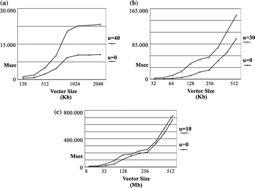
5.2. Scenario 2
In the second scenario, the vector size ranges from 32 to 512 Kb and the number of processors is . The parameters and their values for the first scenario are as follows:
| (1) | |||||
| (2) | Number if processors | ||||
| (3) | Vector size: ranging from 32 to 512 Kb | ||||
| (4) | Real data volumes distributed: 352 Kb–5.5 MB | ||||
| (5) |
| ||||
| (6) |
| ||||
5.3. Scenario 3
In the second scenario, the vector size ranges from 8 to 512 Kb and the number of processors is . The parameters and their values for the first scenario are as follows:
| (1) | |||||
| (2) | Number if processors | ||||
| (3) | Vector size: ranging from 8 to 512 Kb | ||||
| (4) | Real data volumes distributed: 88 Kb–5.5 MB | ||||
| (5) |
| ||||
| (6) |
| ||||
As an observation, one can state that the results the model produces for the three scenarios corroborate each other. In the first scenario, the local processors’ memories were not capable of storing a good percentage of the data carried over the network. While keeps on reducing and the number of processors increases (thus, reducing the bandwidth and the data volumes distributed), the two lines shown in each of the three graphs are converging. The correctness of the results verifies the validity of the model.
6. Conclusions—future research
This paper presents a PN-based model used to verify and evaluate the performance of pipelined parallel distributions. It precisely captures the behavior of a pipeline-based parallel communication system. The model considers message scheduling and message classification, while it is deadlock and contention free. Because it is symmetric, it can easily be used for larger systems only with minor changes. This is one of its biggest strengths.
Future work can include the study of pipelined systems on certain topologies. It is interesting to check if the proposed model (perhaps with minor changes) can be used to study the performance of a data distribution over a torus or mesh network. Also, as already mentioned in the remark of Section IV, an implementation that can take advantage of any empty segments that incur during the distribution is of particular interest. An idea would be the introduction of superclasses (groups of classes).
Additional information
Funding
Notes on contributors
Stavros I. Souravlas
Stavros Souravlas and Manos Roumeliotis are faculty members of the Department of Applied Informatics at the University of Macedonia. They are the authors of three books in the field of Digital Logic Design, Digital Systems Modeling and Simulation with VHDL, and Simulation Techniques. Also, Stavros Souravlas Manos Roumeliotis are members of the Computer and Network Systems Technologies (CNST) group at the University of Macedonia. This group conducts research on the fields of digital systems design, parallel and distributed processing, communication networks, hardware description languages, and modeling and simulation of computer and network systems. This work is a part of a general research project ran by the CNST group on the possible faults that incur when applying parallel algorithms on a multiprocessor network.
References
- Caron, E., & Desprez, F. (2005). Out-of-core and pipeline techniques for wavefront algorithms. In Proceedings of the 19th IEEE International Parallel and Distributed Symposium (IPDPS’05). Denver, CO.
- Chung, Y.-C., Hsu, C.-H., & Bai, S.-W. (1998). A basic-cycle calculation technique for efficient dynamic data redistribution. IEEE Transactions on Parallel and Distributed Systems, 9, 359–377.
- Desprez, F., Dongarra, J., Petitet, A., Randriamaro, C., & Robert, Y. (1998a). Scheduling block-cyclic array redistribution. IEEE Transactions on Parallel and Distributed Systems, 9, 192–205.
- Desprez, F., Dongarra, J., Petitet, A., Randriamaro, C., & Robert, Y. (1998b). More on scheduling block-cyclic array redistribution. In Proceedings of the 4th Workshop on Languages, Compilers, and Run-time Systems for Scalable Computers, volume 1511 of Lecture Notes in Computer Science (pp. 275–287). Pittsburgh, PA: Springer-Verlag.
- Granda, M., Drake, J. M., & Gregorio, J. A. (1992). Performance evaluation of parallel systems by using unbounded generalized stochastic Petri nets. IEEE Transactions on Software Engineering, 18, 55–70.
- Jayachandran, P., & Abdelzaher, T. (2007). A delay composition theorem for real-time pipelines. In Proceedings of the 19th Euromicro Conference on Real-Time Systems, ECRTS ’07 (pp. 29–38). Washington, DC: IEEE Computer Society.
- Kashif, H., Gholamian, S., Pelizzoni, R., Patel, H. D., & Fischmeister, S. (2013, April). ORTAP: An offset-based response time analysis for a pipelined communication resource model. In Proceedings of the 19th Real-Time and Embedded Technology and Applications Symbosium (RTAS). Philadelphia, PA.
- Kaushik, S. D., Huang, C. H., Johnson, R. W. & Sadayappan, P. (1994, July). An approach to communication-efficient data redistribution. In Proceedings of the 8th ACM International Conference on Supercomputing. Manchester.
- King, C. T., Chou, W. H., & Ni, L. M. (1990). Pipelined data-parallel algorithms: Part I: Concept and modeling. IEEE Transactions on Parallel and Distributed Systems, 1, 470–485.
- Kuntraruk, J., Pottenger, W. M., & Ross, A. M. (2005). Application resource requirement estimation in a parallel pipeline model of execution. IEEE Transactions on Parallel and Distributed Systems, 16, 1154–1165.
- Liao, W.-K., Choundary, A., Weiner, D., & Varshney, P. (2004). Performance evaluation of a parallel pipeline computational model for space-time adaptive processing. Journal of Supercomputing, 31, 137–160.
- Navarro, A., Asenjo, R., & Tabik, S. (2009, September). Analytical modeling of pipeline parallelism. In Proceedings of the 18th International Conference on Parallel Architectures and Compilation Techniques. Raleigh, NC.
- Peterson, J. L. (1997). Petri nets*. ACM Computing Surveys (CSUR), 9, 223–252.
- Preud’homme, T., Sopena, J., Thomas, G., & Folliot, B. (2012). An improvement of openMP pipeline parallelism with the BatchQueue algorithm. In Proceedings of the 18th IEEE International Conference on Parallel and Distributed Systems (ICPADS). Singapore.
- Rodrigues, A., Wheeler, K., & Kogge, P. (2008). Fine-grained message pipelining for improved MPI performance. In Proceedings of IEEE Conference on Cluster Computing. Barcelona.
- Souravlas, S. I., & Roumeliotis, M. (2004). A pipeline technique for dynamic data transfer on a multiprocessor grid. International Journal of Parallel Programming, 32, 361–388.
- Souravlas, S. I., & Roumeliotis, M. (2014, March). Verification & performance evaluation of parallel pipelined communications using Petri nets. In IEEE, UKSIM-AMSS, 16th International Conference on Computer Modeling and Simulation (pp. 398–403). Cambridge.
- Ties, W., Chandrasekhar, V., & Amarasinghe, S. (2007). A practical approach to exploiting coarse-grained pipeline parallelism in C programs. In MICRO’07 (pp. 356–369). Chicago, IL.
- Zhang, P., & Deng, Y. (2002). Design and analysis of pipelined broadcast algorithms for the all-port interlaced bypass torus networks. IEEE Transactions on Parallel and Distributed Systems, 23, 2245–2253.
- Zhao, Z., Liu, X., Dou, W., & Yang, K. (2012, October 19--22). Research on data parallel and scheduling mechanism based on Petri nets. In 11th International Symposium on Distributed Computing and Applications to Business, Engineering & Science (DCABES) (pp. 36–39). Guilin.