 ?Mathematical formulae have been encoded as MathML and are displayed in this HTML version using MathJax in order to improve their display. Uncheck the box to turn MathJax off. This feature requires Javascript. Click on a formula to zoom.
Abstract
This paper presents the design of a rotary motion controller based on the peritrochoid geometry of the rotary (Wankle) engine. It uses an orifice limited flow of incompressible fluid between the chambers of the Wankle-type geometry to control the rotation of the rotor. The paper develops the theory of operation and then implements the design as a Matlab model to simulate the motion control under various conditions. It is found that the time to reach stabilised motion is determined by the orifice size and fluid density. When stabilised motion is achieved, the motion dependence on material and geometry factors is determined by the orifice flow equation. The angular velocity is also found to have a square root dependence on the applied torque when in the stabilised regime.
Public Interest Statement
Energy harvesting systems that harvest from mechanical sources, such as human motion, experience intermittent and variable energy generation. Springs offer a way to smooth out the generation of this energy by unwinding at a constant rate, such as in an automatic watch. In watches, this is achieved by an escapement mechanism, but these are not reliable for shocks and vibrations found in energy harvesting environments. This paper shows that an alternative rotary motion controller can be developed using a system based on the geometry of a rotary (Wankle) engine, filled with an incompressible fluid and controlling the flow of the fluid between the three chambers of the geometry. The effect of dimensions and fluid properties on the motion control is studied. The developed system has application in all fields where rotary motion needs to be controlled and if miniaturised, it could act to replace the escapement in mechanical watches.
1. Introduction
Many systems need to control movement of mechanical components, whether it is a shock absorber damping out vibration, machine tool control or the car bonnet gently opening. These motion control tasks are linear in nature and use linear dampers or gas springs (Dixon, Citation2007; Phu & Lee, Citation2014; Zhu, Jing, & Cheng, Citation2012); however, this sets a limit to the length of the motion displacement. In the aforementioned examples, this is not a problem as the required range of motion is naturally limited by the system configuration. There are instances though where the motion is unconstrained and the control needs to be applied continuously. This is the case for rotary motion. A simple crank mechanism can be used to convert the rotary motion to linear motion and then a piston damper can perform the control, but the control is then not smooth and continuous with no applied control at the limit stops of the piston motion. Other mechanisms such as governors with friction pads (invented by Edison (Citation1894) and historically used to control the speed of a gramophone) and electromagnetic braking (Hara, Citation2002) (used in the Seiko spring drive system) have been used in rotary motion control. In watches and clocks, rotary motion control has been carried out successfully for centuries, with the escapement mechanism being used to precisely control the release of energy from a spiral spring to rotate the hands (Bickford, Citation1972; Du & Xie, Citation2013). This innocuous device is providing mechanical control of rotary motion and in its precision has allowed some of the great discoveries in the world to be made.
As with the escapement mechanism, the ability to consistently control the release of energy from a spring offers opportunity for short-term energy storage, and energy harvested from mechanical sources can be stored in spiral springs to be gradually released as it is required, in a similar manner to the operation of an automatic watch or in bursts (Xie, Menet, Ching, & Du, Citation2009; Zurbuchen et al., Citation2013). For many sources of mechanical energy (e.g. a car), the energy harvesting system is exposed to physical shocks, vibration and thermal fluctuations (Kubba & Jiang, Citation2014; Renaud et al., Citation2014; Zuo & Tang, Citation2013). So, the components of the harvesting system need to be shock resistant and temperature invariant. For a spring-based storage, escapement mechanisms are not best suited to this task. Additionally, any significant energy stored in spiral springs creates a large torque that has to be controlled and escapement mechanisms can become very large to cope with this. Hence, a shock-resistant and high-torque control system with a small device volume would be an enabling technology for spiral spring energy storage systems.
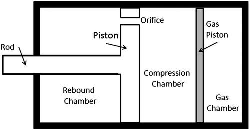
Linear motion control technology may lend itself to this task if a way can be found to implement it in a rotating system. The linear dampers and constant velocity dampers are essentially fluid-filled pistons, where an orifice allows the incompressible fluid to flow from one side of the piston to the other (Figure ) (Meissen, Citation2009). The rate of mass transfer of fluid through the orifice controls the rate () at which the piston moves. For incompressible fluid, the flow through the orifice (Q) is related to the piston movement as,
(1)
(1)
where Ar is the area of the rebound face. Using the equation for flow through a thin wall orifice (Wu, Burton, & Schoenau, Citation2002), the velocity can be related to the pressure difference in the compression (Pc) and rebound (Pr) chambers as,(2)
(2)
where Cd is the discharge coefficient, Ao is the orifice area and ρ is the liquid density. Equation 2 shows the linear dependence of the velocity on the orifice area Ao. However, the linear damper system motion cannot be determined simply from Equation 2 and the forces in the system have to be considered alongside the flow to give the complete system equations as reported in Meissen (Citation2009).
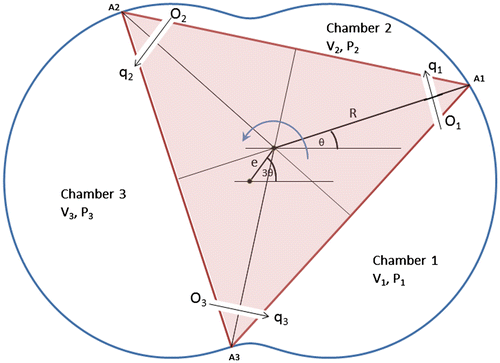
Based on the linear motion controller designs, a mechanical rotary motion controller could be implemented if a system of chambers with a rotating piston could be designed with orifices for fluid flow between the chambers. This problem essentially describes the rotary engine geometry (Figure ) with its triangular piston creating three chambers (Yamamoto, Citation1981). If this geometry was filled with an incompressible fluid and sealed, the rotation of the system would be controlled by the flow of the fluid between the chambers, either through tip seal leakage or by machined orifices in the piston.
This article, to our knowledge, presents first the design and analysis of a rotary motion controller based on the peritrochoid geometry of the rotary (Wankle) engine. In Section 2, the theory of operation for the rotary system is developed and is then implemented in Matlab in Section 3 and simulations undertaken show how the system works to control input torques and produce constant angular velocity motion.
2. Rotary motion controller concept
The rotary motion controller takes the orifice flow concept and uses a peritrochoid geometry with a triangular rotor to implement the pistons and chambers (Figure ) such that they can operate continuously with rotation. The key difference is that the total volume inside the system does not change, but the three chamber volumes vary with rotation. The system works by an external torque being applied to the piston (rotor); this creates a movement of the rotor that creates either an increase or decrease in pressure in each of the chambers; the pressure differentials cause a flow through the orifices and the rotor can move as the incompressible fluid moves between the chambers. A triangular rotor has been chosen to simplify the calculation of the back torque applied to the rotor from the pressure.
2.1. Theoretical model
Referring to Figure , the two-lobe peritrochoid geometry of the housing can be defined by the parametric equations in terms of the rotation angle θ as(3)
(3)
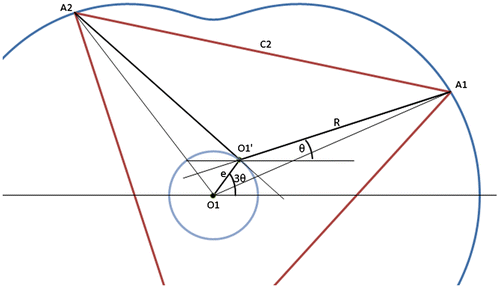
where R is the rotor centre to blade tip distance and e (the eccentricity) is the offset of the rotor centre from the housing centre. From these equations and the orientation of the rotor, the volume of the chambers vs. angle and the rate of change of volume with angle can be determined for any θ. Yamamoto (Citation1981) has calculated the working chamber volume for the system where the rotor is the inner envelope of the trochoid. The same method has been used here to determine the working volume for the triangular rotor configuration but using 3θ = α.
The working chamber volume V can be expressed as V = WA, where A is the area of the chamber surface which is given by A = F1–F2–F3–F4, and referring to Figure , F1 is the area enclosed by the sector A1OA2 of the peritrochoid; F2 is the area enclosed by a third of the rotor A1O′A2; and F3 and F4 are the triangular areas created by the difference in centres of the rotor and the peritrochoids are OA1O′ and OA2O′, respectively and W is the thickness of the rotor/housing.
F1 can be found from the area of a sector of a curve and is given by Yamamoto (Citation1981) as(4)
(4)
The area of the sector of the rotor(5)
(5)
The area of triangles F3 and F4 are simply given as(6)
(6)
Hence, the working volume is determined to be(7)
(7)
which has the same variable element with θ as for the trochoid geometry presented by Yamamoto (Citation1981), but has a different fixed volume; this is as expected, as the rotor volume doesn’t change with rotation, and so the variable aspect is purely set by the housing geometry. The volumes of the two offset chambers can be found by substituting and
for the rotation angles of those chambers, then the volumes are expressed as
(8)
(8)
(9)
(9)
(10)
(10)
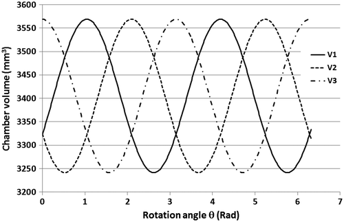
The cyclic nature of the chamber volume and the offset between each chamber are shown in Figure for one full rotation.
Considering the flow through the orifices in Figure , it is seen that there are four possibilities for the resultant flow for a chamber from the two others: in–in, in–out, out–in and out–out. For the analysis, this is simplified to just consider the resultant mass flow Q1, Q2 and Q3 for each chamber. Labelling the orifices as O1 between C1 and C2, O2 between C2 and C3 and O3 between C3 and C1 and then labelling the flows through these orifices as q1, q2 and q3 with positive flow for flow in the direction 1–2, 2–3 and 3–1, respectively, the resultant mass flows are given as(11)
(11)
Assuming identical orifices between the chambers and referring to the pressures in each of the chambers as P1, P2 and P3, the flow equation for each orifice can be written as;(12)
(12)
(13)
(13)
(14)
(14)
where C the prefactor, which is given by(15)
(15)
with terms as defined for Equation 2. However, only two of the Equations, 12–14, are useful as the third is derived from the other two. To solve the system, a simplifying assumption is made which is that the flow through the orifice is inviscid. This assumption allows us to write using the conservation of energy(16)
(16)
where T is the torque input to the system, i.e. the combination of the applied torque Tapp and the back resisting torque Tres from the pressure applied to the piston faces; and G is the rotational inertia of the rotor. The back torque to the first approximation is the pressure force on the rotor being applied through the centre of the eccentric lobe of the drive shaft (the centre of the rotor) and can be calculated from the pressures in the chambers, the face area and the position of the piston as,(17)
(17)
Expanding Equation 16 and writing as
and
as
gives
(18)
(18)
and using Newton’s second law for rotational motion , finally gives
(19)
(19)
Now, assuming incompressible flow, the total flow into the nth chamber can be related to the volume change through(20)
(20)
and writing the pressure differences as ΔP1 = P1 − P2, ΔP2 = P2 − P3, ΔP3 = P1 − P3.
Equations 12–14 can be re-written as(21)
(21)
(22)
(22)
(23)
(23)
Taking two of these, i.e. Equations 21 and 22, with Equation 19 leaves three equations and three variables (P1, P2 and P3) to solve for as Vn and dVn/dθ is known for each chamber n = 1, 2 from the geometry for any θ (Equations 8–10).
3. Simulated results and discussion
3.1. Matlab implementation
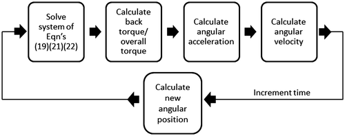
The system of Equations 19, 21 and 23 were implemented in Matlab along with the geometries given in Equations 8–10. An iterative process was employed to solve for the motion of the rotor, where the fsolve function was used to solve the system of Equations to find the pressure of each chamber at a given point in time. These pressures were then used to calculate the back torque leading to the overall torque on the rotor. This was then used to calculate an instantaneous angular acceleration that could be used to find the velocity, and thus the new angle at the end of the time step. This method is shown in Figure .
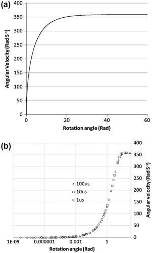
The model was set up to have a starting pressure of atmospheric pressure within each of the chambers. The geometry of the system was such that the eccentricity (e) was 3 mm, the rotor centre to blade tip distance (R) was 21 mm and the thickness of the rotor (W) was 5 mm. The rotor material was set to be a generic plastic of density 2,000 kg m−3; this resulted in a rotational inertia (G) of 9.98 × 10⁻⁷ kg m2 for the rotor. An initial simulation (Figure (a)) was carried out with a working fluid density (ρ) of 1,000 kg m−3, orifice equivalent diameter of 10 mm and applied torque (Tapp) of 0.01 Nm. It is clearly seen that the angular velocity builds up over the initial rotation after the external torque is applied and stabilises at 360 rad s−1 after approximately 10 full rotations. A small amount of oscillation is seen in the angular velocity in the stabilised mode. The angular velocity profile provides clear evidence that the rotary motion controller concept does indeed provide a constant angular velocity output for a given input torque. For this simulation, the time step was found to have no influence on the accuracy of the result at a given time (Figure (b)). The use of the fsolve nonlinear solver ensured that results were consistent. Hence, the time step was adjusted in each of the further simulations to provide the appropriate level of finesse in the data depending on the time for the motion to stabilise.
3.2. Matlab simulation results
The initial simulation looked at the effect of the orifice diameter on the angular velocity profile of the rotor. The orifice diameters were chosen as 10, 7 and 5 mm, giving a range of orifice areas that approximately halved each time the diameter was changed. These orifice diameters are large compared to the chosen rotor thickness, but act to illuminate the effect of the orifice on the final motion. From Equation 15, the flow is proportional to the orifice area, and hence the time steps were halved for each orifice diameter and were set as 10−5 s, 5 × 10⁻⁶ s and 2.5 × 10⁻⁶ s for 10-, 7- and 5-mm diameter orifices, respectively. A further simulation was also carried out where the orifice diameter was reduced to 1 mm and the time step set as 10−6 s; this resulted in less overall rotation but still captured the stabilisation. The results of the simulations are shown in Figure (a). It is seen that for all diameters, the angular velocity increases after the external torque is applied and eventually reaches a constant value. Figure (b) plots the stabilised angular velocity (determined from the flat part of Figure (a)) vs. orifice area; it shows that the stabilised velocity is directly proportional to the orifice area as expected. The number of rotations before stabilisation occurs increases with the increase in diameter; the larger diameter orifices require a higher velocity before the pressure is sufficient to result in orifice limited flow.
Figure 7. (a) Angular velocity vs. rotor displacement for varying orifice diameters, log-log plot; and (b) stabilised angular velocity vs. orifice area.
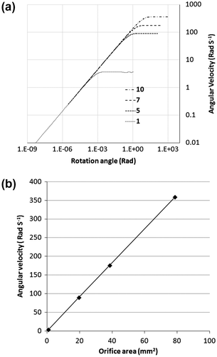
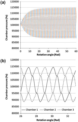
Figure plots the pressure within each of the chambers during the rotation of the rotor for the 10-mm equivalent diameter orifice. It can be seen that the pressure cycles around the quiescent point as the chambers go between increase and decrease in volume. The actual magnitude of the pressure oscillations is seen to increase with the angular velocity; this is to be expected as the angular displacement for each time step will increase with increase in angular velocity, resulting in more compression of the chamber liquid. Figure (b) shows the pressure profile for 1 cycle for each of the chambers during the stabilised motion.
Figure 8. Chamber pressures vs. rotor displacement; (a) build up of pressure from start and (b) pressure variation over one cycle.
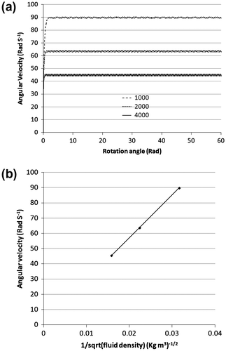
Next, the effect of the working fluid was investigated. Simulations were carried out with an orifice diameter of 5 mm, input torque of 0.01 Nm and the density of the working fluid was chosen to be 1,000, 2,000 and 4,000 kg m−3, respectively. The results of the simulation are shown in Figure . Again, in the orifice limited flow regime, the angular velocity dependence is given by Equation 15 and the inverse square root dependence can be seen in Figure (b).
Figure 9. (a) Angular velocity vs. rotation angle for varying fluid density; and (b) density dependence of the angular velocity.
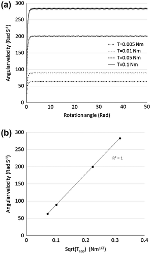
The final simulation investigates the angular velocity dependence on applied torque. The system of Equations 19, 21 and 22 do not contain torque as a parameter, but they are used to find the back torque on the system through Equation 17; and the overall torque is then the difference between the applied torque and back torque. Simulations were carried out with an orifice diameter of 5 mm, working fluid density of 1,000 kg m−3 and torque was varied as 0.005, 0.01, 0.05 and 0.1 Nm; Figure (a) shows the results of the torque simulation with angular velocity increasing with increase in torque. The applied torque dependence of the angular velocity is shown in Figure (b) where the angular velocity is plotted vs. the square root of the applied torque (Tapp) and shows a perfect linear relationship (R2 = 1), ω ∝ √Tapp.
4. Conclusions
A concept has been presented for a rotary motion controller based on fluid-orifice flow control using a peritrochoid geometry to allow continuous rotary motion. The model equations relating the applied torque to pressure in the chambers and the angular acceleration have been developed with an assumption of inviscid flow in the orifices. The system has been implemented in Matlab and solved using an iterative process to show that after an initial period of acceleration and stabilisation, the Wankle-type rotary motion controller concept does indeed produce constant angular velocity for a given input torque. Fluid density and orifice area dependence of the stabilised angular motion are given by the orifice equation. Torque dependence is seen to be of a square root nature. Hence, the angular velocity of the system can be designed through geometrical and material properties, for a given input torque. The rotary motion controller has a potential for replacing the escapement-based control in timepieces, with a sealed shock invariant oil-filled system, reducing the number of gear parts required in the timepiece movement, as well as being used for control of energy release in spring-based energy harvesting systems.
However, the model presented has simplifications regarding the nature of the fluid flow through the orifices. Inviscid flow assumes no viscosity and so no turbulent energy loss. The applied torque is therefore converted entirely into rotational energy and this will affect the accuracy of the results from the model. The next phase of work will develop the model with the effects of viscosity for comparison to the simplified model presented here, as well as look at tip seal and face seal leakage effects on the flow-controlled motion.
Additional information
Funding
Notes on contributors
Julio Cesar Caye
Carl Julio Caye is a student studying Mechanical Engineering at the Universidade Federal de Santa Catarina in Brasil. As part of his studies, he undertook a yearlong overseas placement at the University of Birmingham in the UK, through the Science Without Borders programme. The work presented in this paper is the result of an individual project that he undertook whilst at Birmingham under the supervision of Carl Anthony. Carl Anthony’s research is in the field of microsensors, but with an interest in energy harvesting systems to power remote microsensors. This project arose from the need to control the release of energy from spiral springs that were planned to be used for energy storage in an in-wheel mechanical energy harvesting system. The requirement to have a system that would provide constant angular velocity and be relatively immune to the harsh vibrations seen within the wheel led to the idea of a motion controller based on a Wankle engine geometry.
References
- Bickford, J. H. (1972). Mechanisms for intermittent motion. New York, NY: Industrial Press.
- Dixon, J. C. (2007). The shock absorber handbook (2nd ed.). Chichester: Wiley.10.1002/9780470516430
- Du, R., & Xie, L. (2013). The mechanics of mechanical watches and clocks. In History of mechanism and machine science (Vol. 21). Berlin Heidelberg: Springer-Verlag. doi:10.1007/978-3-642-29308-5_2
- Edison, T. A. (1894). U.S. Patent No. 513 095. Washington, DC: U.S. Patent and Trademark Office.
- Hara, T. (2002). U.S. Patent No. US20020191493 A1. Washington, DC: U.S. Patent and Trademark Office.
- Kubba, A. E., & Jiang, K. (2014). A comprehensive study on technologies of tyre monitoring systems and possible energy solutions. Sensors, 14, 10306–10345. doi:10.3390/s140610306
- Meissen, C. (2009). Development and validation of a physical model for a modern twin tube damper (MS thesis). Colorado State University, Fort Collins, CO.
- Phu, N. M., & Lee, G. S. (2014). Characteristics of pressure and force considering friction in a closed cylinder with a holed piston. Journal of Mechanical Science and Technology, 28, 1–9. doi:10.1007/s12206-014-0533-4
- Renaud, M., Wang, Z., Jambunathan, M., Matova, S., Elfrink, R., Rovers, M., & van Schaijk, R. (2014). Improved mechanical reliability of MEMS piezoelectric vibration energy harvesters for automotive applications. In Proceedings of the Micro Electro Mechanical Systems (MEMS) IEEE International Conference (pp. 568–571). San Francisco, CA. doi:10.1109/MEMSYS.2014.6765704
- Wu, D., Burton, R., & Schoenau, G. (2002). An empirical discharge coefficient model for orifice flow. International Journal of Fluid Power, 3, 13–19. doi:10.1080/14399776.2002.10781143
- Xie, L. H., Menet, C. G., Ching, H., & Du, R. X. (2009). Automatic winding device of a mechanical watch movement and its application in energy harvesting. ASME Transaction: Journal of Mechanical Design, 131, 8–15. doi:10.1115/1.3151803
- Yamamoto, K. (1981). Rotary engine. Tokyo: Sankaido.
- Zhu, X., Jing, X., & Cheng, L. (2012). Magnetorheological fluid dampers: A review on structure design and analysis. Journal of Intelligent Material Systems and Structures, 23, 839–873. doi:10.1177/1045389X12436735
- Zuo, L., & Tang, X. (2013). Large-scale vibration energy harvesting. Journal of Intelligent Material Systems and Structures, 24, 1405–1430. doi:10.1177/1045389X13486707
- Zurbuchen, A., Pfenniger, A., Stahel, A., Stoeck, C. T., Vandenberghe, S., Koch, V. M., & Vogel, R. (2013). Energy harvesting from the beating heart by a mass imbalance oscillation generator. Annals of Biomedical Engineering, 41, 131–141. doi:10.1007/s11517-012-0989-2

