
 ?Mathematical formulae have been encoded as MathML and are displayed in this HTML version using MathJax in order to improve their display. Uncheck the box to turn MathJax off. This feature requires Javascript. Click on a formula to zoom.
Abstract
Presented in this study is an investigation of the real-time performance of a laboratory-scale model of wind turbine emulator. Developed to provide a cost-effective experimental facility for demonstrating and validating wind energy conversion systems at new wind territories, the emulator comprises a software component with a hardware interface of a motor-driven wound rotor induction generator. A real-life wind speed profile is implemented on the model to investigate its performance under a near-real-world scenario and, some operational characteristics of real wind energy conversion systems are exactly replicated by the emulator in the course of the experimentation. The emulator could therefore be considered suitable for use as a laboratory level testbed for the demonstration and validation of wind energy conversion systems in the real-time.
Public Interest Statement
In spite of the limited generating capacities, demand for electric power continues to increase in most of the third world nations. A major among the reasons for crippled national economies in these nations is the persistence erratic power supply. With global acceptance of renewable energies, one critical challenge that is common to most of the indigenous electricity industries in these nations is the absence of research, development and demonstration facilities that could enable them to accurately validate and qualify renewable energy systems for their operations. This paper therefore presents a simple and cost-friendly laboratory-level teaching and research facility on wind energy conversion systems, which could help in validating the wind energy potential of new territories, towards seamless penetration of wind power-based electric microgrid technology into the national electric energy mixes of the developing nations.
1. Introduction
By the increasing adoption of renewable energy technologies (RETs) across the globe, it is envisaged that at some point in the future, the so called alternative energies may likely become the primary sources of meeting the global energy demands. Wind energy conversion (WEC) technology in particular, has been adjudged by Omole (Citation2010) as a promising electric power resource that though currently supplements the fossil-based electricity generation, yet may eventually replace the conventional in the long run as the global availability of the latter rapidly declines. The fact, however, remains that electric utility companies would not want to adopt any of the emerging technologies at a new territory unless such has been accurately validated via demonstration within the territory. Therefore, for the growing desire of some developing African nations to leverage on renewable energy resources for secured electric power generation, facilities for teaching, research and development on RETs must be affordably available.
One technical approach to RET systems validation is development of demonstration testbeds for the experimentation of the technologies (Hajimiragha, Dadash-Zadeh, & Moazeni, Citation2015; Sachs & Sawodny, Citation2016). In Lasseter and Piagi (Citation2004), Abby, Katiraei, Brothers, Dignard-Bailey, and Joos (Citation2006), Morozumi (Citation2007), Kroposki, Pink, Basso, and DeBlaiso (Citation2007), several testbeds are described that employ the facilities or portion of the facilities of existing power system networks to demonstrate RET-based microgrids. This practice could be very expensive to achieve and so make it unaffordable in many of the developing nations. A way of overcoming this challenge is the use of RET system emulating models that can provide suitable and reduced-cost testing and demonstration environments.
A model of a hybrid system comprising of solar, wind and hydroelectric, which is developed on the platform of MATLAB/Simulink, is presented in Dumitru and Gligor (Citation2010) to help in the analysis and simulation of a real hybrid solar-wind-hydroelectric system that is connected to a public grid. Architecture of the model is built in such a way that facilitates easy study of each component module. Each of the blocks like solar model, wind model, hydroelectric model, energy conversion and the load can be implemented separately on the system. Modeled in Ghazanfari, Hamzeh, and Mokhtari (Citation2011) is a distributed generation (DG) composed of fuel cell (FC) and super-capacitor (SC) units. The model is developed for the purpose of studying system reliability and power sharing between the units in order to propose a suitable and fast power sharing and control strategy. To interface DG systems to electric power network, a model of power converter is presented in Chandralekha, Musthafa, and Kethamreddy (Citation2011). The idea is to control the inverter for distributed generation systems requiring power quality features such as harmonic and reactive power compensation for grid-connected operation. Ustun, Ozansoy, and Zayegh (Citation2012) used IEC61850-7-420 in modeling a microgrid to study system protection, safety and overall reliability. In Anand and Fernandes (Citation2013), a reduced-order modeling approach is used to study RET microgrids, while Rasheduzzaman, Mueller, and Kimball (Citation2015), and Yu, Ai, Wang, Ni, and Lv (Citation2016) employed the small-signal modeling technique. However, the ability of a system emulator to accurately and demonstratively capture the real-time operational characteristics of the system it is designed to replicate is a prime factor in determining the dependability of such emulator as testing, research and demonstration facility. Hence, the need for validation of the performances of RET system emulator in the real-time, prior to deployment.
This study therefore presents a near-real-world demonstration of a laboratory-scale model of WEC system. The model is developed to emulate the operations of wind turbine, thereby providing a cost-friendly testing and demonstrating environment for WEC technology. A real-life wind speed profile is implemented on the model for real-time performance evaluation. Location of the wind capture is Obafemi Awolowo University, Ile-Ife, Nigeria (Latitude 7.5°N/Longitude 4.3°E) at a turbine height of 114 m. The choice of the location for wind profiling is premised on the desire of the university to leverage on the available renewable energy resources for an autonomous electricity generation in order to enhance the security of power supply within the campus community. Also, while turbine with tower as high as 160 m has been made possible through daily improvement in WEC technology, 114 m is the highest that is commercially available to date (Wu, Lang, Zargari, & Kouro, Citation2011). The emulator is in this study investigated for its ability to calculate and turn-in the power of the wind mass and, the controllability of the angle of attack of the wind flow on the rotor blades by the pitching mechanism. The speed of the emulator’s hub, the mechanical power and the mechanical torque developed by the hub are also demonstrated. Production of real power with the corresponding reactive power consumption by the generator, and the power factor of the generator are investigated as well. These operational regions of real wind turbine are found to be properly captured by the emulator in the course of the demonstration and the actual characteristic behaviours are presented in this paper.
2. Materials and methods
2.1. Design description of the emulator
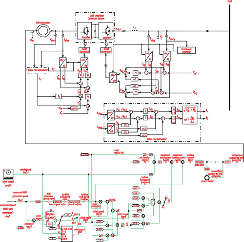
The emulator is made up of hardware components that are interfaced with a software model as shown in Figure . The soft component is developed on the platform of the real-time simulation computer aided design of the real time digital simulator (RTDS) using the components model library blocksets. Signal output of the soft component excites a direct current motor that has been conditioned to operate in torque control mode with an external analogue voltage signal. The actual electric power is generated by a wound rotor induction (WRI) machine driven by a servo-motor. The generator with the grid interface converter system constitutes the hardware component of the emulator.
Figure 1. The wind turbine emulator.
Wind turbines are generally characterized by the tip speed ratio (TSR) and the power coefficient. The TSR is the ratio of the hub speed to the speed of the wind mass.(1)
(1)
The mechanical power extractable from the wind mass by the rotating turbine blades is described by Abad, López, Rodríguez, Marroyo, and Iwanski (Citation2011) as:(2)
(2)
Power coefficient is the ratio of the mechanical energy obtained from the wind to the actual energy in the wind. For modern turbines, power coefficient ranges from 0.2 to 0.5 (Keyhani, Citation2011). The coefficient depends on the pitch angle, which is the angle at which the turbine blades can be rotated about its longitudinal axis to provide the mechanism by which energy in the wind can be cut off when the wind speed reaches a dangerously high value that might cause damage to the turbine. Agarwal, Aggarwal, Patidar, and Patki (Citation2010) describes a common way of calculating the power coefficient as(3)
(3)
Λi, which is a function of the pitch angle and the TSR, is described as:(4)
(4)
Equation (2) exhibits the feature of the turbine mechanical power passing through a maximum point and to locate the point, the equation is differentiated with respect to the turbine speed.(5)
(5)
A gear unit on the soft component adapts the speed of the turbine to that of the generator, has the ratio, rgb, obtained as:(6)
(6)
2.2. Control of the hardware interface
In Figure , the control of the system is shown as the WRI generator is made to deliver power to the local grid through an interface converter sub-system. From the space-vector model of a WRI generator, Equations (7)–(9) respectively describe the generator’s voltage, flux and dynamic behaviour of the rotor mechanical speed (Krause, Wasynczuk, & Sudhoff, Citation2002).(7)
(7)
(8)
(8)
(9)
(9)
Operation of the controller is based on decoupled control of d- and q-axes. The rotor circuit of the WRI generator is connected to the rectifying part of the grid-feeding converter to enabled the regulation of the generator’s speed and torque through direct field oriented control method (Keyhani, Citation2011). Grid voltage orientation control is employed on the converter, wherein the grid voltage angle is detected and employed for the necessary Park’s and inverse-Park’s transformations. Stator voltage and current of the generator are vsabc and isabc, while vgabc and igabc are the grid voltage and current respectively. Pref and Qref are the reference active- and reactive powers supplied to the controller. The converter unit is a rectifier-inverter pair whose purpose is to achieve maximum power tracking (Goel, Singh, Murthy, & Kishore, Citation2011), maintain active- and reactive-power balance at the load terminals, as well as to regulate the magnitude and the frequency of the load voltage (Guerrero, Hang, & Uceda, Citation2008).
2.3. Implementation of the real-life wind speed profile
By design, the emulator has a maximum mechanical power output of 500 W at 12 m/s rated wind speed. The analog real-life wind speed data feeds into the facility through the input scheduler of the software component. The scheduler contains an analog/digital converter and, the giga-processor (GP) card of the RTDS calculates the mechanical speed of the emulator from the rotor speed measured by an encoder. Torque output of the soft model is multiplied by the ratio of the gear system, and then converted to voltage signal for the excitation of the interface motor. The conversion is achieved in the motor drive with the analogue full scale torque limit set to the rated torque of the motor. Voltage signals corresponding to the intantaneous torques developed at different wind speeds are thus fed into the motor through the drive. The expected electric power is generated as the motor drives the directly connected three-phase WRI machine at a super-synchronous speed. In Figure , the super-synchronous speed of the induction machine is compared with the overall mechanical power that is developed by the emulator as a result of the speed of the direct current motor at the rated wind. The figure shows that a maximum mechanical power of 500 W is produced at the speed of 196.44 rad/s. Figure is the image of the actual model as employed for the experimentation.
Figure 2. Speed of the WRI generator versus mechanical power of the emulator at the rated wind speed.
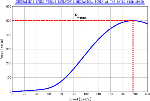
Figure 3. A picture showing part of the hardware component of the experimental set-up.

3. Result and discussion
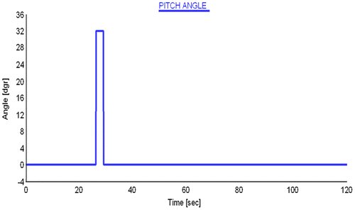
Table gives the specifications used in the simulation while Figure is the profile of the real-life wind speed normalized by the GP card. The corresponding power of the wind mass is shown in Figure as calculated and turned-in by the card. At a period when the wind speeds is as low as 7.5 m/s, which is below the designed cut-in speed of the emulator, the pitching mechanism got activated as Figure reveals, thereby causing the blades to stop rotating by changing the angle of attack from 0° to 32°. For the rest of the experimental period however, the angle was kept at the optimal value of 0° such that the emulator was able to capture the maximum power available from the wind mass throughout the period of the wind flow.
Table 1. Simulation specifications
Figure 4. The real-life wind speed profile normalized by the RTDS.
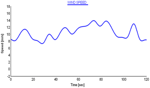
Figure 5. Wind power as returned by the GP card.
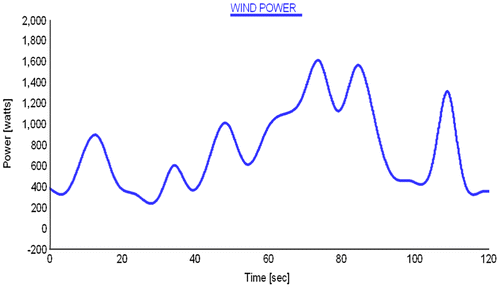
Figure 6. Blade pitching behaviour of the turbine emulator.
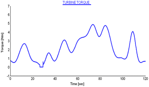
The speed developed by the emulator’s hub due to the power of the wind mass, is as shown in Figure , while Figures and respectively show the mechanical power and the corresponding mechanical torque developed by same. The figures reveal that no mechanical power (and torque) is developed during the pitching period, thereby showing the effectiveness of the pitching mechanism in protecting the system against excessive in-rush of wind.
Figure 7. Developed speed of the turbine emulator.
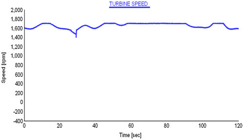
Figure 8. Power developed by the turbine emulator.
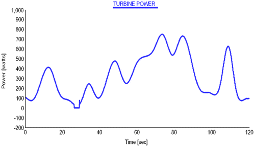
Figure 9. Torque developed by the turbine emulator.
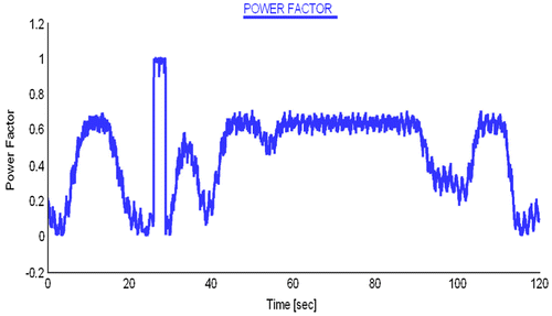
Except during the pitching, the induction machine runs at super-synchronous speed throughout the duration of the experiment as the characteristic plot of Figure shows. Real power is continuously generated by the machine, with a corresponding drawing of reactive power from the grid as presented in Figure . For the reactive power consumed by the generator, a power factor as low as 0.6 is developed by the system as shown in Figure .
Figure 10. Rotating speed of the induction generator.
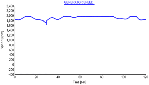
Figure 11. Electrical powers produced by the WEC source emulator.
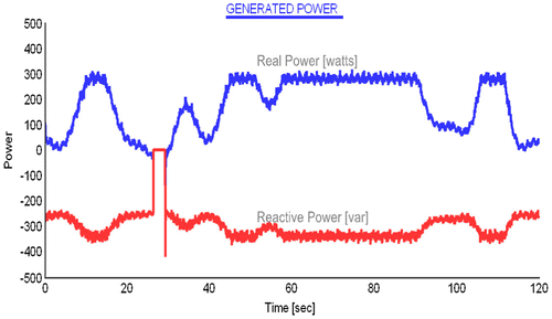
Figure 12. Power factor of the system.
4. Conclusion
The real-time performance of a laboratory-scale model of WEC system is investigated with the implementation of a real-life wind speed profile. With the inflow of the wind mass, the emulator was able to calculate and turn-in the power of the mass, likewise the control of the angle of attack of the wind flow on the rotor blades was achieved by the pitching mechanism, thus safety measure against excessive in-rush of wind speed is provided through the mechanism. By the rotation of the emulator’s hub, the WRI machine unit was driven at super-synchronous speed causing the generation of real power, with a corresponding drawing of reactive power from the host local grid. The need for reactive power compensation on the WEC system is revealed with the low power factor developed by the induction machine.
The practical operational regions of wind turbine are properly captured in this demonstration experiment. The emulator was found perfectly mimicked the real-time behaviours of real wind turbines. Reliability of the emulator as a laboratory-level facility for teaching, testing, and validation of WEC systems at new wind territories is thus established. Utility companies in developing nations could therefore consider adopting the emulator as an accurate and affordable tool for validating WEC technology for their operations. The emulator can also serve as a laboratory-level teaching facility.
| Nomenclature | ||
| Λ | = | tip speed ratio |
| ωtb | = | turbine speed |
| A | = | swept area of the turbine rotor blades |
| R | = | radius of the swept area |
| v | = | speed of the wind |
| Pm | = | output mechanical power developed by the turbine hub |
| C | = | power coefficient |
| rgb | = | gearbox ratio |
| ωss | = | super-synchronous speed of the induction machine |
| = | stator, rotor voltage vectors | |
| = | stator, rotor current vectors | |
| = | stator, rotor flux-linkage vectors | |
| ω | = | rotating speed of the arbitrary reference frame |
| ωr | = | rotor electrical angular speed |
| Ls, Lr | = | stator, rotor self-inductance |
| Lls, Llr | = | stator, rotor leakage inductance |
| Lm | = | magnetizing inductance |
| J | = | moment of inertia of the rotor |
| P | = | number of pole-pairs |
| Tm | = | mechanical torque from the generator shaft |
| Te | = | electromagnetic torque |
| ωm | = | rotor mechanical speed |
| RETs | = | renewable energy technologies |
| WEC | = | wind energy conversion |
| RET | = | renewable energy technology |
| RSCAD | = | real-time simulation computer aided design |
| RTDS | = | real time digital simulator |
| DG | = | distributed generation |
| FC | = | fuel cell |
| SC | = | super-capacitor |
| CML | = | component model library |
| WRI | = | wound rotor induction |
| DFOC | = | direct field oriented control |
| GVOC | = | grid voltage orientation control |
| ADC | = | analog/digital converter |
| GP | = | giga-processor |
Additional information
Funding
Notes on contributors
Titus Oluwasuji Ajewole
Titus Oluwasuji Ajewole and Kehinde O. Alawode are lecturers at the Osun State University, Osogbo, Osun, Nigeria, while Michael O. Omoigui is currently a Professor in the same institution. Waheed A. Oyekanmi is with the DNV-LG Energy Advisory, Dallas, Texas, USA. This is a research group that is working on providing technical approaches that could foster seamless penetration of renewable-energy-based electric microgrid technology into the Nigerian national electric energy mix in the quest for the enhancement of the reliability and security of electric power supply to the Nigerian end users.
Related Research Data
References
- Abad, G., López, J., Rodríguez, M., Marroyo, L., & Iwanski, G. (2011). Doubly fed induction machine (pp. 1–100). Hoboken, NJ: Wiley.10.1002/9781118104965
- Abby, C., Katiraei, F., Brothers, C., Dignard-Bailey, L., & Joos, G. (2006, June). Integration of distributed generations and wind energy in Canada. Proceeding of IEEE Power Engineering General Meeting, Montreal.
- Agarwal, V., Aggarwal, R., Patidar, P., & Patki, C. (2010). A novel scheme for rapid tracking of maximum power point in wind energy generation systems. IEEE Transactions on Energy Conversion, 25, 228–236.10.1109/TEC.2009.2032613
- Anand, S., & Fernandes, B. G. (2013). Reduced-order model and stability analysis of low-voltage DC microgrid. IEEE Transactions on Industrial Electronics, 60, 5040–5049.10.1109/TIE.2012.2227902
- Chandralekha, R., Musthafa, P., & Kethamreddy, S. (2011). The enhancement of power quality control strategy for single-phase inverters in distributed generation systems. International Journal of Advanced Engineering, Sciences and Technologies, 8, 58–64.
- Dumitru, C. D., & Gligor, A. (2010). Modeling and simulation of renewable hybrid power system using matlab/simulink environment. Scientific Bulletin of the Petru Maior University of Targu Mures, 7, 5–9.
- Ghazanfari, A., Hamzeh, M., & Mokhtari, H. (2011, November 3–4). Application of multi-hybrid fuel cell/energy storage power conversion system in an autonomous microgrid. Paper presented at the Conference on Power Electronics for Industrial Applications and Renewable Energy Conversion, Doha.
- Goel, P. K., Singh, B., Murthy, S. S., & Kishore, N. (2011). Isolated wind-hydro hybrid system using cage generators and battery storage. IEEE Transactions on Industrial Electronics, 58, 1141–1153.10.1109/TIE.2009.2037646
- Guerrero, J. M., Hang, L., & Uceda, J. (2008). Control of distributed uninterruptible power supply systems. IEEE Transactions on Industrial Electronics, 55, 2845–2859.10.1109/TIE.2008.924173
- Hajimiragha, A. H., Dadash-Zadeh, M. R., & Moazeni, S. (2015). Microgrids frequency control considerations within the framework of the optimal generation scheduling problem. IEEE Transactions on Smart Grid, 6, 534–547.10.1109/TSG.2014.2375251
- Keyhani, A. (2011). Design of smart power grid renewable energy systems (pp. 175–246). Hoboken, NJ: Willey.
- Krause, P., Wasynczuk, O., & Sudhoff, S. (2002). Analysis of electric machinery and drive systems (pp. 415–470). Hoboken, NJ: Willey.10.1109/9780470544167
- Kroposki, B., Pink, C., Basso, T., & DeBlaiso, R. (2007, June). Microgrid standard and technology development (pp. 1–4). Proceeding of IEEE Power Engineering Society General Meeting, Tampa, FL.
- Lasseter, R., & Piagi, P. (2004, June). Microgrids: A conceptual solution (pp. 4285–4290). Proceeding of IEEE Power Engineering Conference, Aachen.
- Morozumi, S. (2007, April). Microgrid demonstration projects in Japan (pp. 635–642). Proceeding of IEEE Power Conversion Conference. Nagoya.
- Omole, A. (2010). Voltage stability impact of grid-connected photovoltaic power systems utilizing dynamic reactive power control (Unpublished doctoral dissertation). University of Florida, Gainesville, FL.
- Rasheduzzaman, M., Mueller, J. A., & Kimball, J. W. (2015). Reduced-order small-signal model of microgrid systems. IEEE Transactions on Sustainable Energy, 6, 1292–1305.10.1109/TSTE.2015.2433177
- Sachs, J., & Sawodny, O. (2016). A two-stage model predictive control strategy for economic diesel-pv-battery island microgrid operation in rural areas. IEEE Transactions on Sustainable Energy, 7, 903–913.
- Ustun, T. S., Ozansoy, C., & Zayegh, A. (2012). Modeling of a centralized microgrid protection system and distributed energy resources according to IEC 61850-7-420. IEEE Transactions on Power Systems, 27, 1560–1567.10.1109/TPWRS.2012.2185072
- Wu, B., Lang, Y., Zargari, N., & Kouro, S. (2011). Power conversion and control of wind energy systems (pp. 25–175). Hoboken, NJ: Willey.10.1002/9781118029008
- Yu, K., Ai, Q., Wang, S., Ni, J., & Lv, T. (2016). Analysis and optimization of droop controller for microgrid system based on small-signal dynamic model. IEEE Transactions on Smart Grid, 7, 695–705.