 ?Mathematical formulae have been encoded as MathML and are displayed in this HTML version using MathJax in order to improve their display. Uncheck the box to turn MathJax off. This feature requires Javascript. Click on a formula to zoom.
Abstract
In this paper the results of static and dynamic tests carried out with an instrumented handle are presented and discussed. The instrumented handle was designed and constructed to be directly mounted on the handlebar of a two-wheeled vehicle and it can measure simultaneously grip, force transmitted by the handlebar to the hand and acceleration at the handle interface. The results of repeatability tests on the hand-arm weight and grip static measurement without and with real-time measure feedback show the importance of the use of an instrumented handle to ensure repeatability and also to estimate the influence of such parameters on the dynamic response. On the basis of preliminary dynamic tests conducted with the handle mounted on a shaker, the hand-arm system was characterized on two subjects, through a spectrum of its mechanical impedance as function of the excitation frequency, for different postures and grip levels. The results were compared to literature ideal impedance curves with acceptable agreement. The effect of grip showed to increase impedance in some specific frequency ranges.
Public Interest Statement
In this article, a suitable measuring tool for the dynamic characterization of the human hand-arm system subject to vibration is introduced. The device is portable and can be directly mounted on the handlebar of a two-wheeled vehicle so that field tests can be performed as well as lab tests. Lab tests have demonstrated the validity of the device and the results could find application to derive a lumped parameter model to be used in two-wheeled vehicle dynamics simulation and design.
1. Introduction
Human exposure to vibration is one of the main problems of interaction between humans and machines; in particular the transmitted vibrations can cause harm or discomfort, depending on their intensity and duration of exposure (Griffin, Citation1996; ISO, Citation1997, Citation2001). Although the characterization of exposure to vibration is based primarily on the acceleration measurement of the vibrating surface in contact with the hand, it is also recognized by the international standards that biological effects are due in large part to the transmitted energy and therefore to both the transmitted force and the interface velocity.
In the technical literature on the vibrations transmitted to the hand-arm system, the system is characterized equivalently by its apparent mass, mechanical impedance, and apparent stiffness measured at the hand-driving point (Dong, Welcome, McDowell, & Wu, Citation2006). In particular the mechanical impedance is defined as as:
(1)
(1)
where F(ω) and V(ω) represent respectively the transmitted force and speed of the handle measured at the same point and direction; both quantities are complex functions of frequency.
The significant dispersion of the experimental data reported in the literature, (e.g. Gurram, Rakheja, & Brammer, Citation1995) underlines the strong dependence of mechanical impedance from the various test parameters, including posture and grip. Although grip is a physically intuitive quantity, its measurement is quite complex, since it is related to contact actions at the interface with variable direction, totally self-balanced. Commonly it is a static measurement made with spring dynamometers, handles equipped with strain gauges (Burström & Lundström, Citation1994; Chadwick & Nicol, Citation2001), pressure sensor mats (Scalise, Rossetti, & Paone, Citation2007; Welcome, Rakheja, Dong, Wu, & Schopper, Citation2004), etc. Before the dynamic tests, the operator is invited to reproduce the same grip on the handle (Burström & Lundström, Citation1994; Reynolds & Angevine, Citation1977), with an obvious difficulty of repeatability. A measuring handle with two caps for the simultaneous measurement of grip and transmitted force was firstly proposed and patented by Forte, Di Puccio, and Bechi (Citation2005). The same concept was adopted for laboratory devices (Adewusi, Rakheja, Marcotte, & Boutin, Citation2010; Dong et al., Citation2009) with measurements recently extended in the three directions (Knez, Slavič, & Boltežar, Citation2013).
In the field, however it is generally possible to get only an approximate estimation of the transmitted force, and therefore of the power, by accelerometer measurements, through the values of impedance from the literature or obtained by laboratory tests. Therefore a device that can interface with vibrating machines and directly measure the forces transmitted to the hand is of practical interest. Instrumented adapters to be used for the measurement without changing the original handle structure have been proposed and analysed in (Burström & Lundström, Citation1998). However the uncertainty inherent in such measures is highlighted in (Dong, Wu, & Welcome, Citation2005; Xu, Dong, Welcome, Warren, & McDowell, Citation2014) where some indications are given for improving adapter design and use.
In this article, a particular instrumented adapter for the dynamic characterization of the human hand-arm system subject to vibration is introduced. Such a device was designed to provide a better understanding of the interaction between the motorcycle and the driver undergoing parameters variations. The present work is part of a research activity aimed at the evaluation of scooter comfort, and is particularly focused on the vertical vibrations transmitted by the handlebar to the hand-arm system (Di Puccio, Forte, Pratesi, & Hippoliti, Citation2002). This aspect appears important especially for new generation scooters designed for long routes. A model of the driver’s hand-arm system for comfort evaluation in the design stage would be quite useful to the vehicle designer. The present study could provide the basis for the development of a lumped model of the hand-arm system, starting from the determination of its mechanical impedance. It should be remarked that the case of the motor scooter handle is not exactly similar to those generally dealt with in the literature because the latter are obtained with high grip forces (related for example to heavy tools) and with different excitation sources. Therefore specific tests are mandatory.
2. Materials and methods
2.1. The instrumented handle
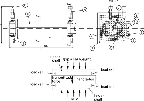
An important quantity for the vibrations transmitted to the hand-arm system is the force with which the handle is gripped (grip). Since there are no commercial devices that can simultaneously measure the resultant force transmitted to the hand by the handle and the grip, especially in dynamic conditions, a special instrumented handle was designed and constructed (Forte et al., Citation2005) (Figures and ). The instrumented handle can be directly interfaced with the vehicle bare handlebar (that is without the rubber cover), keeping the same outer diameter of the original one. It was designed so as not to alter the dynamic response of the handlebar and having a measuring range up to 1,000 Hz, that is, with frequencies greater than 1,000 Hz. The design proved to be rather complicated and a compromise solution was obtained taking into account the characteristics of the measuring system, the device dynamic response, its overall dimensions, weight and cost.
Figure 2. Pictures of the instrumented handle with accelerometer and a load cell with a ball contact point.
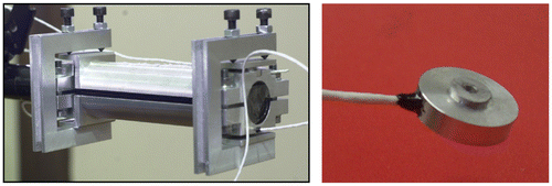
With reference to Figure , the handle is constituted by two aluminium cylindrical half-shells (element No. 8), each supported at the ends by two small uniaxial button load cells (element No. 6) (12.5 mm diameter, 3.5 mm thickness), housed in aluminium blocks (element No. 2) fixed to the handlebar. Other authors have proposed an apparently similar configuration for lab fixtures (Knez et al., Citation2013), and thus with less interface and size constraints.
The cells can measure both static and dynamic loads from 0 to 50 N. Steel balls (element No. 10) housed in conical seats were interposed between the shells and the load cells in order to counteract the sensitivity of the transducers to load direction and point of application, concentrating the transmitted load at the center of the load cells. Since the cells work in compression, two brackets (element No. 9) ensure the necessary preload.
The handle is also provided with flat surfaces in order to mount an accelerometer in the shaking direction. In particular, the accelerometer has a mass of 0.65 g, a sensitivity of 0.174 mV/ms−2, a natural frequency of 118 kHz.
The shape of the handle was optimized on the basis of its dynamic response obtained by a finite element analysis so as to obtain their frequencies outside the range of interest. The first two calculated natural frequencies were above 1,000 Hz and that was confirmed experimentally afterwards.
2.2. Load cell data processing
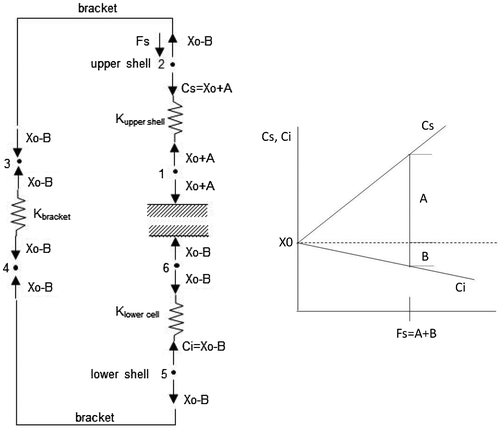
Due to the presence of the clamping brackets the handle is a statically indeterminate structure. Therefore a one-dimensional lumped parameter model of the handle, detailed in Appendix A, was developed to interpret and process the force values measured by the load cells. Figure (left) shows an example of the model equilibrium diagram in the case of only the force Fs applied to the upper shell. Cs and Ci are the loads measured by the upper and lower cells, respectively, X0 is the preload of the cells, A is the increase in load on the upper cells due to Fs and B the corresponding load decrease on the lower cells. The unknowns A and B vary linearly with the force Fs as shown in Figure (right); the gradients of the straight lines of the measured load as function of the applied load are characteristics of the system; it is also noted that the two slopes are significantly different due to the different stiffness of the elements along the path between the loaded shell and the corresponding cell, and between the loaded shell and the opposite cell.
Figure 3. Model of the handle indeterminate system (left) and upper and lower cell measured loads as function of applied load (right) in the case of load on upper shell.
In general on the two halves of the handle there are opposed loads (Fs on the upper and Fi on the lower), in addition to the weight of the moving parts of the equipment, the weight of the hand-arm system and the preload. The model allows to precisely derive these loads from the measured forces. In particular, the weight is the difference of the average values of Fs and Fi, the grip is equal to the minimum value of Fs and Fi, and the dynamic force transmitted to the hand-arm system is the difference of the variations of Fs and Fi from their average values.
2.3. Static calibration tests
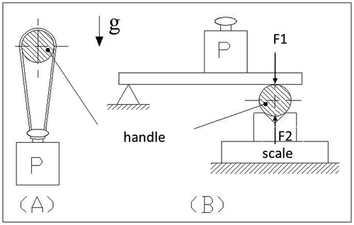
Calibration tests were carried out on the device as a whole by applying known vertical loads, as calibrated weights (P, from 1 to 35 N), according to sketch A of Figure . Data were acquired and processed using the model described above. The correlation between identified and applied loads revealed a good accuracy of the measuring system especially for loads less than 20 N and a slight underestimate of the actual value of the force for higher loads (for P = 35 N the error was 2.8%).
In order to validate the model used for the determination of grip, other static calibration tests were carried out by applying a known grip, force according to sketch B of Figure , by means of two opposite vertical forces (F1 and F2), equal to less than the handle own weight. Even in this case the correlation of the identified grip and the applied one indicated a satisfactory accuracy of the measuring system with an average error less than 1% although the experimental points had a certain dispersion (about 1.5 N at the most). The maximum error in the measurement was estimated about 2% due to the accuracy of the employed load cells.
2.4. Static tests with an operator
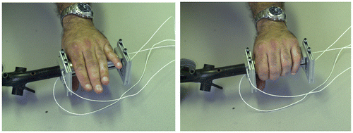
Once the correct performance of the handle and the reliability of data acquisition and processing were verified, other static tests were conducted with the forces exerted by an operator without him having a real- time feedback on the measures. The aim of these tests was to see if the force Ft exerted by the operator, in a certain posture, could be held constant within a test campaign. A first series of tests was made simply by placing his hand on the handle without exerting a grasping force, as shown in Figure left; thus the Ft force with which the limb rests statically on the handlebar was measured. To give statistical significance to the test, measurements were repeated by the same operator about 40 times.
The subsequent tests were done with the hand grasping the handle as occurs in driving a scooter (Figure right). In this case the aim was to investigate the possibility for the operator to exert a well-determined value of grip for several times. Two series of tests were conducted in the sitting and standing postures.
2.5. Dynamic tests
The dynamic tests were aimed at obtaining curves of mechanical impedance as function of the excitation frequency in the range from 10 to 1,000 Hz, also to compare the results with those reported in the literature. They were conducted using a shaker (TV 5110) set so as to reproduce constant amplitude sinusoidal one frequency excitations, with an operating range from 2 Hz to 7 kHz, in the vertical direction as this was the most significant component for the application of interest. The shaker can generate a maximum acceleration of 51 g. The signals were acquired at a sampling frequency of 5,000 Hz and each test was 3 s long.
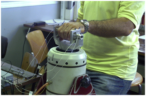
Since the handle can be directly interfaced with the scooter handlebar, for the dynamic tests, a support connecting the handle and the shaker was manufactured to reproduce the scooter handlebar. Figure presents the experimental equipment on the shaker and the operator seated during a dynamic test.
The weight of the hand-arm system, the grip and the force transmitted by the handle were determined according to the model described in Appendix A. In particular static or quasi- static forces (weight and grip) were obtained from the average values of the force signals.
The dynamic force transmitted by the handle was derived from the part of the signal variable in time. Transforming the force acquired signals from the time to the frequency domain yields its complex value (with the respective magnitude and phase) for the given excitation frequency. From the acceleration data, it is possible to obtain velocity and, through equation 1, the mechanical impedance modulus and phase for the considered excitation frequency. A direct measure of power was not possible but tests showed its negligible influence on mechanical impedance.
3. Results and discussion
Figures and report the results obtained from the static tests in sitting and standing postures, with an elbow angle of 90° in the case of no real-time feedback to the operator. The results show that, even with no grasping (Figure ), trying to keep the same posture and approximately the same muscle contraction, there is a significant dispersion on the value of Ft. Variations due to posture could have been minimized controlling it electronically using markers on arm joints or simply a jig for the operator arm. However, since the focus of the investigation was on the possibility of grip and static force real time measurement, the effect of posture variation was only observed and treated as disturbance and thus minimized by test repetition and statistical processing.
Figure 7. Force Ft transmitted by the hand-arm system to the handle with sitting posture (left) and standing posture (right) and no grasping; the force Ft on the abscissa axis divided into intervals, the number of times that the measure fell in a given interval on the ordinate axis.
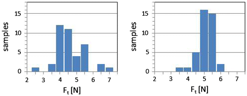
Figure 8. Grip and mean force Ft transmitted by the hand-arm system to the handle with sitting posture (upper) and standing posture (lower) with grasping; in the histograms: grip on the abscissa axis divided into intervals, the number of times that the measure fell in a given interval on the ordinate axis.
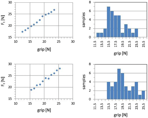
For each test the force Ft was also calculated and its mean value is shown in the graphs of Figure as a function of grip. From these results it appears that Ft increases with grip, with an almost linear trend. In any case, although the operator was convinced to apply the same grasping force (15 N required), the results, represented in the histograms of Figure , showed a dispersion of the actual value.
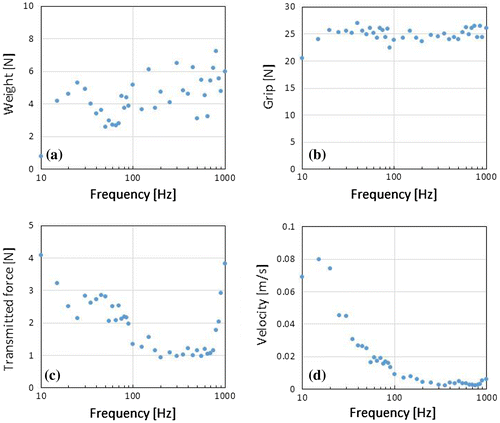
The results reported in Figure refer to tests in which the operator could check the measure of the grip in real-time, in particular the operator was seated and was asked to apply a 25 N grip. It is noteworthy that in this case the operator was able to maintain the required grip during the dynamic test within a tolerance of about ±1%. As regards the trends of the other quantities with the excitation frequency, weight is rather scattered while both the dynamic transmitted force and velocity magnitudes decrease except near the end of the tested frequency range where the dynamic transmitted force tends to increase abruptly due to the nearby handle resonance, indicating one of its performance limits.
Figure 9. Weight (a), grip (b), dynamic transmitted force magnitude (c), velocity magnitude (d) as function of frequency.
These results therefore show that, without a real-time feedback, the assumption of maintaining a constant grip during the execution of a series of tests, as assumed in the past (e.g. Burström & Lundström, Citation1994; Reynolds & Angevine, Citation1977), was very strong, as this parameter is not completely stationary. On the contrary, as assessed by more recent studies (Adewusi et al., Citation2010; Dong et al., Citation2009; Knez et al., Citation2013), a direct measurement of the grip for each single dynamic test simultaneously with the other significant quantities, as obtainable with the instrumented handle, allows to appreciate with greater accuracy the dependence of the impedance from the mechanical grip. All these tests also indicated the importance of the subjective factor for this kind of studies, since the setting of certain muscle characteristics is not perfectly controllable and repeatable.
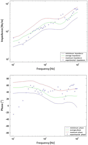
Figure shows magnitude and phase of the mechanical impedance obtained from the dynamic tests described above, compared to the ideal envelopes proposed by Gurram et al. (Citation1995) for the most probable values of impedance magnitude and phase of the human male hand arm in the 10–1,000 Hz frequency range. The latter are obtained from tests conducted by various authors in different ways as regards the excitation (sinusoidal, pulsed, random) and the grip value (10 to 110 N), and as regards the posture (operator’s arm bent at a variable angle from 60 to 180°) and the handle diameter. The impedances are referred to as idealized in the sense that the contours encompass the impedance characteristics reported in all the investigations judged suitable for synthesis and have also been suitably smoothed. In any case, impedance maximum values can be even twice the minimum ones. Considering the ideal nature of the envelopes embracing quite different test conditions, the agreement of the present experimental results is acceptable.
Figure 10. Mechanical impedance spectrum in terms of magnitude and phase compared to Gurram model values (Gurram et al., Citation1995).
In Figure it is finally possible to compare the conditions of sitting and standing posture, tight (25 N) and light (10 N) grip, for two different operators. The test grip values were selected because they are representative of two grip conditions of the handle for a two-wheeled vehicle during a ride on a smooth pavement. Moreover these values correspond to those more commonly adopted in the tests reported in the literature. While regarding the posture there is not a clear trend, for the same posture most of the tests showed that impedance slightly increases with grip except for some frequency bands (<30 Hz and 100–200 Hz) where the difference of the applied grip has a more meaningful impact. In the low frequency range there seems to be a resonance (associated to the impedance valley) on which grip has also the effect of increasing the frequency as the system becomes stiffer. Also in (Adewusi et al., Citation2010) the authors highlighted that at some specific frequencies the grip influenced the hand-handle interaction by increasing the transmissibility but unfortunately a direct comparison was not possible because the posture was completely different.
Figure 11. Mechanical impedance spectra for two different operators and different postures and grip levels.
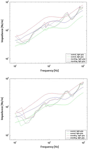
Comparing the response of the two operators, quite different in size and weight (a tall stout man and a short slim woman), lower impedance values can be observed in the second case. The other trends are confirmed, as regards the effect of grip as well as the presence of an impedance peak in the frequency band 300–400 Hz and a valley around 500 Hz which could be an anti-resonance and a resonance but further investigation is needed for interpretation, aided by a multi-degree of freedom lumped parameter model of the hand-arm system.
4. Conclusions
An original instrumented handle that can be directly interfaced with a scooter handle made it possible to carry out a test campaign to characterize the hand-arm system of a scooter driver both statically and dynamically.
The static tests showed the validity of the data acquisition and processing system. Therefore it was possible to conduct an extensive static test campaign that pointed out that some test parameters such as the force exerted by the hand-arm system on the handle due to its own weight cannot be considered constant. In fact although the operator’s posture was well defined and he tried to lay his hand in the same way, the results showed a certain scatter. Also the grip was scattered although the operator was convinced to exert the same grip all along.
The repeatability tests proved that the assumption of keeping some parameters constant during a test campaign is inadequate while the use of an instrumented handle, which can measure simultaneously weight and grip during the test giving a feedback to the operator, appears essential and is also very useful to estimate the influence of such parameters on the dynamic response.
A series of dynamic tests, with the operator simulating a motor scooter driver, yielded the spectrum of the hand-arm mechanical impedance amplitude and phase as a function of the excitation frequency. The abrupt increase of the transmitted force around 1 kHz, ascribed to the handle nearby first resonance, confirmed a performance limit of the device. The comparison of such spectra with the most probable impedance curves reported in the literature showed some similarities and some differences. The latter can be ascribed to the fact that the literature impedance curves are obtained averaging results from tests carried out with wide parameter ranges, removing outliers and smoothing the curves.
The effect of grip showed to increase impedance in some specific frequency ranges but further investigation must be carried out with the support of a dynamic model of the hand-arm system in order to better interpret the observed trends.
As future work, an experimental campaign with more subjects should be carried out in order to get statistically significant impedance data. Moreover a control system could be set up in order to study the effect of posture variation on impedance value. Finally, dynamic tests could be carried out on the vehicle, mounting the handle on the real handle-bar.
Acknowledgement
The author acknowledges the collaboration of the co-inventors of the patented handle.
Additional information
Funding
Notes on contributors
Paola Forte
Paola Forte is an associate professor of Machine Design of the University of Pisa, Italy. She co-authored more than 170 papers in national and international journals and proceedings and 4 patents. Her research is related to vibrations and noise of machines, their damping and transmission to humans with particular attention to smart materials and comfort.
References
- Adewusi, S. A., Rakheja, S., Marcotte, P., & Boutin, J. (2010). Vibration transmissibility characteristics of the human hand–arm system under different postures, hand forces and excitation levels. Journal of Sound and Vibration, 329, 2953–2971.10.1016/j.jsv.2010.02.001
- Burström, L., & Lundström, R. (1994, May). Absorption of vibration energy in the human hand and arm. Ergonomics, 37, 879–890.10.1080/00140139408963697
- Burström, L., & Lundström, R. (1998). Portable equipment for field measurement of the hand’s absorption of vibration energy. Safety Science, 28, 15–20.10.1016/S0925-7535(97)00060-X
- Chadwick, E. K. J., & Nicol, A. C. (2001). A novel force transducer for the measurement of grip force. Journal of Biomechanics, 34, 125–128.10.1016/S0021-9290(00)00168-8
- Di Puccio, F., Forte, P., Pratesi, A., & Hippoliti, R. (2002). Assessment of discomfort due to motor scooter hand-transmitted vibration (SAE Technical Paper 2002-01-2176). doi:10.4271/2002-01-2176
- Dong, R. G., McDowell, T. W., Welcome, D. E., Warren, C., Wu, J. Z., & Rakheja, S. (2009). Analysis of anti-vibration gloves mechanism and evaluation methods. Journal of Sound and Vibration, 321, 435–453. doi:10.1016/j.jsv.2008.09.044
- Dong, R. G., Welcome, D. E., McDowell, T. W., & Wu, J. Z. (2006). Measurement of biodynamic response of human hand–arm system. Journal of Sound and Vibration, 294, 807–827.10.1016/j.jsv.2005.12.047
- Dong, R. G., Wu, J. Z., & Welcome, D. E. (2005). Recent advances in biodynamics of human hand-arm system. Industrial Health, 43, 449–471.10.2486/indhealth.43.449
- Forte, P., Di Puccio, F., & Bechi, A. (2005). Dispositivo per monitorare la trasmissione di vibrazioni da una sorgente a un sistema mano-braccio di un soggetto, Patent n.PI2005A000096, Italy.
- Griffin, M. J. (1996). Handbook of human vibration. London: Academic Press.
- Gurram, R., Rakheja, S., & Brammer, A. J. (1995). Driving-point mechanical impedance of the human hand-arm system: Synthesis and model development. Journal of Sound and Vibration, 180, 437–458.
- ISO. (1997). ISO2631: Mechanical vibration and shock—Evaluation of human exposure to whole-body vibration.
- ISO. (2001). ISO5349: Mechanical vibration—Measurement and evaluation of human exposure to hand-transmitted vibration.
- Knez, L., Slavič, J., & Boltežar, M. (2013). A Multi-Axis Biodynamic Measuring Handle for a Human Hand-Arm System. Strojniški vestnik - Journal of Mechanical Engineering, 59, 71–80. doi:10.5545/sv-jme.2012.709
- Reynolds, D. D., & Angevine, E. N. (1977). Hand-arm vibration, part. II: Vibration transmission characteristics of the hand and arm. Journal of Sound and Vibration, 51, 255–265.10.1016/S0022-460X(77)80035-7
- Scalise, L., Rossetti, F., & Paone, N. (2007). Hand vibration: Non-contact measurement of local transmissibility. International Archives of Occupational and Environmental Health, 81, 31–40.10.1007/s00420-007-0190-3
- Welcome, D., Rakheja, S., Dong, R., Wu, J. Z., & Schopper, A. W. (2004). An investigation on the relationship between grip, push and contact forces applied to a tool handle. International Journal of Industrial Ergonomics, 34, 507–518.10.1016/j.ergon.2004.06.005
- Xu, X. S., Dong, R. G., Welcome, D. E., Warren, C., & McDowell, T. W. (2014). An examination of the handheld adapter approach for measuring hand-transmitted vibration exposure. Measurement, 47, 64–77. doi:10.1016/j.measurement.2013.08.037
Appendix A: Analytical model
With only the preload the measured load is:(A1)
(A1)
where Cs, Ci are the forces measured by the upper and lower cells, respectively, while X0s, X0i are the preloads measured by the upper and lower cells with the handle in the right side up position (,
in the upside down position), respectively, their difference corresponding to the weight of the handle.
When the hand grasps the handle, a force Fs due to the weight of the hand-arm system and to palm grip is applied on the upper shell, while on the lower shell a force Fi due to finger grip is applied.
Referring to the experimental curves of the measured loads as function of the load applied separately on the upper and on the lower shell (Figure ), one has:(A2)
(A2)
Figure A1. Experimentally measured loads on upper and lower cells as function of applied load on upper shell (handle in right side up position) and on lower shell (handle in upside down position).
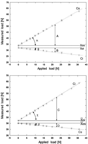
where A is the increase of Cs due to Fs, B the decrease of Ci due to Fi, C the increase of Ci due to Fi and D the decrease of Cs due to Fi.
Moreover:(A3)
(A3)
where α, β, χ, and δ are the characteristic slope angles of the load functions of the upper and lower cells. Thus:(A4)
(A4)
Considering linearity, the effects of Fs and Fi on the measured loads can be superimposed, yielding:(A5)
(A5)
Using Equations (A4) and (A5) and measured loads, preloads and characteristic angles, it is possible to calculate A, B, C, and D and, from Equation (A2), Fs and Fi.
Assuming grip G a self-balanced force system, one obtains:(A6)
(A6)
and for hand-arm weight:(A7)
(A7)
In dynamic conditions, the forces Fs and Fi are frequency dependent. At each frequency ω, grip and weight are obtained from the average values of Fs(ω) and Fi(ω) while the dynamic transmitted force from the variation, with respect to the average value, of such forces.

