 ?Mathematical formulae have been encoded as MathML and are displayed in this HTML version using MathJax in order to improve their display. Uncheck the box to turn MathJax off. This feature requires Javascript. Click on a formula to zoom.
Abstract
Recent advances in sensors, low-power integrated circuits, and wireless communications have enabled the design of low cost, miniature, lightweight, and intelligent physiological sensor nodes. These nodes, capable of sensing, processing, and communicating one or more vital signs, can be seamlessly integrated into wireless personal or body sensor networks (WPSNs or WBSNs) for health monitoring. This paper describes and proposes the implementation of Heart rate sensor node for embedded telemedicine system. The heart rate sensor node in embedded telemedicine system that has been designed for healthcare applications will be presented. A short description of key enabling technologies (i.e. sensor technology, communication technology, and system analysis and design) that have allowed researchers to implement telemedicine systems is followed by a detailed description of major areas of application of wearable sensors technology. Applications described in this paper include those that focus on health and wellness, safety, home rehabilitation, assessment of treatment efficacy, and early detection of disorders.
Public Interest Statement
Healthcare monitoring affected millions of people in the world. It is innovative in structural, financial, medical, and emotional terms. This research work describes sensor node design to collects vital sign of heart beat, which was used to illustrate impacts on patient’s health status. It was found that, the innovative proposed system can also help government and non-government organizations to improve health communities and individuals in the emphasizing what is inspirational or innovative of telemedicine. We began the work by building a small microcontroller bases sensor board. We implement this targeting system to get a wearable device for patient monitoring. We developed programs on microcontroller to collect data from sensors node and send it to mobile device through blue tooth. This unit is promising to be a core of an efficient wearable device for human vital signs monitoring. The system is allowing doctors to give special treatment for huge network of patients in different places simply from their houses, hospitals or clinic.
1. Introduction
This paper is organized by discussing sensor technology in telemedicine applications, discussing the communication technologies which used for telemedicine and compare between them upon the used application, then discussing the physiological parameters, then we describe the design of heart rate sensor node according to the physiological signs. We designed the data base to register the vital signs measurements and then send them to the doctor for diagnoses by internet through mobile application or website. We did the simulations of circuit design of heart rate sensor node using proteues program to do design iterations and improve the results. The comparison of our results and the state of the art then declare the added value of our contribution of this work.
1.1. Sensor technology
Wireless body sensors network (WBSN) is a special purpose sensor network that incorporates different networks and wireless devices to enable remote monitoring for various vital signs (Fouad, Citation2016). One of the targeted applications of WBSN is medical environments where conditions of large number of patients are continuously being monitored in real-time. Wireless monitoring of physiological signals of large number of patients is one of the current needs in order to deploy a complete wireless sensor network in healthcare system. Such an application presents some challenges in software and hardware designs. Some of them are as follows: reliable communication by eliminating collisions of two sensor signals and interference from other external wireless devices, low-cost, low power consumption, and providing flexibility to the patients (Fouad & Farouk, Citation2015). A wireless medical sensor network system when implemented in medical centers has significant advantages over traditional wired-based patient-data collection schemes by providing better rehabilitation and improved patient’s quality of life. In addition a WBSN system has the potential to reduce the healthcare cost as well as the workload of medical professions, resulting in higher efficiency. “Wearable” sensors are miniature electronic devices worn on the body, often integrated with or designed to replace existing medical accessories. This market segment is booming, enabled by Internet of Things technology. Some of the current trends are smart watches, smart glasses, and sports and fitness activity trackers. In addition to the consumer market, the medical industry is creating the demand for devices that monitor physiological conditions and functions (Yuce & Ho, Citation2008).
1.2. Communication technology
The wireless system in WBSN uses medical bands to obtain physiological data from sensor nodes. The medical bands are selected to reduce interference and thus increase the coexistence of sensor node devices with other network devices available at medical centers. The collected data is transferred to remote stations with multi-hopping technique using medical gateway. The gateway nodes connect the sensor nodes to local area network and the Internet for global access. As such facilities are already available in medical centers; medical professions can access patients’ physiological signals anywhere in medical center. The data can also be accessed outside the medical center as they will be made available on the Internet. Most popular wireless communication technologies and protocols proposed in medical monitoring systems are listed in Table . Existing monitoring systems use the short-range wireless systems such as ZigBee (IEEE 802.15.4) (Chan, Poon, Wong, & Zhang, Citation2007; Gao, Greenspan, Welsh, Juang, & Alm, Citation2005; Otto, Jovanov, & Milenkovic, Citation2006), WLANs (Anliker et al., Citation2004; Gao et al., Citation2005), GSM (Anliker et al., Citation2004) and Bluetooth (IEEE 802.15.1) (Jong, Istepanian, Alesanco, & Wang, Citation2005; Proulx, Clifford, Sorensen, Lee, & Archibald, Citation2006; Rasid & Woodward, Citation2005). To make the power consumption and the size of the device low, short-range devices like Bluetooth and ZigBee are mostly used with sensors to collect medical data from patient body. Especially WLAN technologies are avoided for low power sensor nodes because of their large size and power consumption used to provide longer ranges (i.e. 100 m). As these technologies may most probably be installed in medical environments due to other applications, medical gateway devices should be designed in WBSN to interface with these wireless systems to provide wireless link between control unit and mobile device (i.e. PALM) or between the control unit and Internet via Wi–Fi link. The low-data rate IEEE 802.15.4 technology (ZigBee) has been the most popular short-range standard used recently in medical monitoring systems due to its low transmitter power (Golmie, Cypher, & Rebala, Citation2005; Timmons & Scanlon, Citation2004). Medical Systems using Zigbee wireless platform may however suffer from strong interference by WLANs which share the same spectrum and transmit at larger signal power (Ho & Yuce, Citation2008). Installing an interference free medical network in hospital may thus be quite challenging since there exist a lot of other wireless systems and equipment using 2.4 GHz band.
Table 1. Usage of wireless protocols in wireless sensor network applications
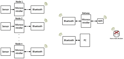
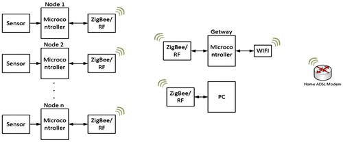
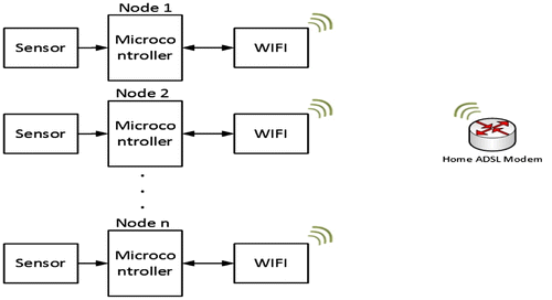
The device technologies operating at 2.4 GHz ISM band should thus deal with interference and coexistence issues when they are located in the same environment (Golmie et al., Citation2005). As can be seen in Table , in addition to unlicensed ISM bands, there are medical bands such as MICS (Medical Implant Communication Service) and WMTS (Wireless Medical Telemetry Service) that are specifically regulated for medical monitoring by communication commissions around the world (Golmie et al., Citation2005; Ho & Yuce, Citation2008; Timmons & Scanlon, Citation2004). The recent short-range, low-data rate, ultra-wideband (UWB) technology is another attractive technology that could be used for body-area network applications because of its regulated low transmitter power (Yazicioglu, Merken, Puers, & Van Hoof, Citation2007). For min cost target: we can use WiFi or RF, whereas for min power consumption we may use RF. For min size we may use WiFi because it does not need MicroController but it has max power consumption so we can use sleep mode And needs IP for every sensor, For long range and min power consumption we may use Zigbee (Figures –).
Bluetooth notes:
| (1) | Small sized module is not available in Egypt, We may import smaller sized modules. | ||||
| (2) | Limited coverage range. | ||||
| (3) | Need microcontroller to interface with it, which will increase the circuit size. | ||||
| (4) | One to one connection. | ||||
| (5) | Need gateway. | ||||
ZigBee notes:
| (1) | Need extra extension for the connection with the smartphone. | ||||
| (2) | Need a microcontroller to interface with it, which will increase the circuit size. | ||||
| (3) | Expensive. | ||||
| (4) | Need a gateway. | ||||
WiFi notes:
| (1) | Every node acts as a single independent node. | ||||
| (2) | Small circuit size. | ||||
1.3. Physiological parameters
The complete wireless body-area network is based on different frequencies in order to eliminate interference issues as well as to apply to different environments. We use MICS, WMTS and 433 ISM bands to detect signals from the sensors on the body. The goal in a WBAN application is to dedicate one sensor node to one physiological signal to eliminate placing wires on the patient body. The physiological parameters that are monitored are Electrocardiogram (ECG), heart rate derived from ECG signals by determining the R-R intervals, blood pressure, body temperature, Galvanic Skin Response (GSR), Oxygen saturation in blood (SaO2), respiratory rate, Electromyogram (EMG), Electroencephalogram (EEG) and three axis movement of the subject measured using an accelerometer. Figure illustrates the specifications of the physiological signals being monitored in telemedicine system (Hanna, Citation2009; Yuce, Keong, & Chae, Citation2009).
Figure 4. Overall architecture of wireless sensor network monitoring many channels simultaneously (Yuce et al., Citation2009).
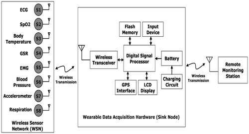
However, there may be some clinical applications that require the monitoring of more channels of the same physiological signal simultaneously to provide good quality screening (Fouad, Citation2014). More channels may be required when considering EEG signal for brain activities. For the applications that require monitoring of more channels such as ECG/EEG/EMG, we incorporate the UWB technology to achieve high data rate wireless link [20] as shown in Figure (a) and (b). We also like to point out that we are working to interface our devices with IEEE 802.15.4 (ZigBee) and WiFi links to cover a large area of body-area network. The selection of wireless schemes for sensor nodes will depend very much on the environment that the sensor nodes will be used. Ultra wideband (also known as UWB or as digital pulse wireless) is wireless technology for transmitting large amounts of digital data over wide spectrum of frequency bands with very low power for short distance. Ultra wideband radio not only can carry a huge amount of data over a distance up to 230 feet at very low power (less than 0.5 mW), but has the ability to carry signals through doors and other obstacles that tend to reflect signals at more limited bandwidths and higher power. Ultra wideband can be compared with another short-distance wireless technology, Bluetooth, which is a standard for connecting handheld wireless devices with other similar devices and with desktop computers. UWB broadcasts digital pulses that are timed very precisely on carrier signal across very wide spectrum (number of frequency channels) at the same time. Transmitter and receiver must be coordinated to send and receive pulses with an accuracy of trillionths of a second. On any given frequency band that may already be in use, ultra wideband signal has less power than the normal and anticipated background noise so theoretically no interference is possible. Time Domain, a company applying to use the technology, uses a microchip manufactured by IBM to transmit 1.25 million bits per second, but says there is the potential for data rate in the billions of bits per second.
2. Proposed design of heart rate sensor node
The body-area network prototyping system presented uses multi-hopping structure where the MICS band is used for gathering signals from sensors and WMTS is used to transmit the sensor data to remote stations allowing longer range monitoring. These frequency bands are internationally available and are permitted for remote monitoring of several patients simultaneously. The MICS band has low emission power (25 μW, comparable to UWB) leading to lower power consumption, and will thus provide one of the most suitable transmission bands for medical sensor nodes [21, 22]. Although a few incidents have been reported due to the interference from some local TV channels in USA, WMTS is still the most popular band for wireless telemetry used in hospitals (Golmie et al., Citation2005). The MICS regulations require that the output power of any terminal must be kept under −16dBm and is not intended for long-range wireless connections (Ho & Yuce, Citation2008; Timmons & Scanlon, Citation2004). To facilitate a long-range communication, a WMTS link operating in the 608–614 MHz band is used between the CCU and the base station allowing for much longer range. This implies that the intermediate CCUs must be able to operate both at MICS and WMTS frequencies, providing link between the nodes and the computer. The CCU remains in close range with the patient and may be attached to their belt for example when it is for individual use. The nominal wireless distance for the MICS link is around 10 m. The WMTS link targets a distance more than 100 m.
Sensor nodes are designed to collect raw signals from human body. The signal from human body is usually weak and coupled with noise. First, the signal should go through amplification and filtering process to increase the signal strength, and to remove unwanted signals and noise. After which, it will go through Analog to Digital conversion (ADC) stage to be converted into digital for digital processing. The digitized signal is then processed and stored in the microprocessor. The microprocessor will then pack those data and transmit over the air via transmitter (see Figure ). The overview of Pulse Rate Sensor Node is shown in Figure . As can been seen, the pulse rate sensor node comprises. Microcontroller PIC16F877 and the transceiver AMIS-5210 are selected in the project because of the following reasons: low-power consumption, size, and the suitability operating at the MICS band and for the physiological data processing (Ho & Yuce, Citation2008). Figure shows the hardware implementation of sensor nodes. Both temperature and pulse rate sensor nodes were built on common PCB circuit. Thus the electronics can be used interchangeable. The antennas for this project are designed as loop printed around the prototyping boards (Figure ). Hardware implementation of Pulse Rate Sensor Node is shown in Figure . The CCU also requires a micro-controller and a wireless transceiver chip to coordinate all activities similar to the sensor nodes.
Figure 6. Block diagram of pulse rate sensor node (Yazicioglu et al., Citation2007).

The CCU hardware is made of the same transceiver chip from AMI semiconductor (AMI52100 IC) and the microcontroller PIC16F87 [23]. The targeted wireless distance between sensors and the CCU (the MICS link) is 1–10 meters. The CCU can thus be located at the waist of the patient or at an easily accessible place.
(a) Central Control Unit (CCU) hardware designs:
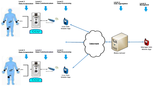
Two different CCU boards are designed to realize the scenarios given in Figure . One CCU is designed to be connected to computer via the USB port Figure (a). The other CCU given in Figure (b) functions as intermediate device (i.e. wireless gateway) that presents the WMTS wireless link. Although both CCUs can be used for multiple patients monitoring, the first CCU type can also be useful for private usage at patients’ home or for single patient monitoring in hospital. It can receive the physiological signals directly from sensors without using the gateway CCU.
The hardware for CCUs requires microcontroller and wireless transceiver to coordinate all the activities, similar to sensor boards. The CCU-1/sensor nodes consist of transceiver (AMI52100IC) from AMI semiconductor used for the MICS band generation (we also used CC1000 in some sensor nodes to generate 433 MHz ISM and WMTS bands for sensors-CCU wireless connections) and the microcontroller-PIC16F887. In addition to these chips, we use another transceiver CC1010 chip from Chipcon (this chip contains CC1000 and a microcontroller built-in) on the intermediate CCU board (CCU-2) to obtain wireless transmission and networking with the WMTS band. The CC1010 and CC1000 transceiver chips can be configured to transmit anywhere within 300 and 1,000 MHz frequencies. They have been programmed to operate with one of WMTS bands in our prototype system. The wireless chips AMI52100 IC and CC1000 are selected in the project because of the following reasons: overall cost saving, low-power consumption, size, and suitability of operating at the MICS, WMTS, and 433MHzISM bands. AMIS has data rate capability of 19 kbps while CC1010 provides 76 kbps. The proposed sensor board includes transceivers, microcontroller and sensor front-end electronics, consumes power of 90 mW for transmit mode and less than 30 mW for receive mode when operating with supply voltage of 3.3 V.
(b) Database, software programs and monitoring:
Since all sensor nodes of body are communicating with the same CCU, the data is prefixed with identifier that is used to identify source of data. To reduce collisions further between data sent, a firmware (media access layer (MAC) protocol) is written to control data transmissions. The communication between sensors and CCU is bidirectional as to support multi user (i.e. multi-patient) communications. To illustrate multi user implementation, we need at least 2 users with two sensors (each user uses two sensors) and one CCU for test and demonstrations of the extensive software packages developed. The experimental setup is given in Figure .
A media access layer (MAC) protocol for firmware at both sensor node and CCU is developed to prove bidirectional communication. The system was designed using CSMA/CA (Carrier Sense Multiple Access with Collision Avoidance) MAC protocol to accommodate multi-patient medical data transfer. In this design we used RTS/CTS (Ready To Send/Clear To Send) feature of the MAC protocol for reliable transfer of medical records. When a sensor node wants to send data to the CCU first it will check the transmission channel. If the node finds the channel is free then it will transmit an RTS packet otherwise the node will backoff for future transmission attempt. On successful reception of RTS packet the CCU will send a CTS packet confirming the acceptance of the transmission. By reading the CTS packet information other nodes will remain in quite state allowing the transmitting node to capture the channel and transmit its own information. The transmitting node will release the channel as soon as the transmission of information packet is complete. This simple MAC protocol allows multiple sensor nodes to reliably transmit their data to the CCU without any significant delay. A developed software at the local PC to communicate with the CCU to get readings from sensors and then forward them through the network/internet to an application on a remote PC (at medical center).
While performing this task, the program also verifies the data integrity and schedules retransmission if required. Another software program is developed at the remote PC (called BSN) who gets readings from GATEWAY via network/internet. These readings are stored in the remote PC for analysis. The program is also able to display readings for multiple users. An example of live monitoring from our set up is shown in Figure . It displays temperature and pulse rate information of two patients at the same time. The graph allows up to 20 readings to be displayed. Every sensor device has a unique Sensor ID and must be registered under a patient name before they are used. In the event that an unregistered sensor node is used, all its readings received will be discarded by the BSN application.
2.1. Circuit analysis of proposed heart rate sensor node
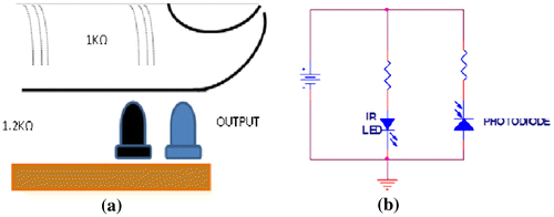
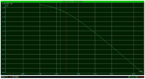
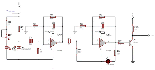
The sensor consists of an IR light emitting diode transmitter and an IR photo detector acting as the receiver as shown in Figure . The IR light passes through the tissues. Variations in the volume of blood within the finger modulate the amount of light incident on the IR detector. Two practical configurations could be implemented to achieve this function. In this design, both the IR transmitter and receiver could be placed on the same plane and the finger would function as a reflector of the incident light instead. The IR receiver monitors the reflected signal in this case. The IR filter of the photo transistor reduces interference from the mains of 50 Hz. Figure shows the pulse detection circuit. The IR LED is forward biased through a resistor to create a current flow. The values of resistors are chosen so that they produce the maximum amount of light output. The photo-resistor is placed in series with the resistor to reduce the current drawn by the detection system and to prevent short-circuiting the power supply when no light is detected by the photo resister. Here we are getting digital output. In the proposed design 60s is considered as delay, so that after 1 min it will start counting from beginning. The signal conditioning circuit as shown in Figure consists of two identical active low pass filters with a cut-off frequency of about 2.5 Hz. This means the maximum measurable heart rate is about 150 bpm. The operational amplifier IC used in this circuit is LM358, a dual Op-Amp chip from Microchip, I’ve replace it with LM324 from Texas Instruments It operates at a single power supply and provides rail-to-rail output swing. The filtering is necessary to block any higher frequency noises present in the signal. The gain of each filter stage is set to 101, giving the total amplification of about 10000. A 2.2 μF capacitor at the input of each stage is required to block the dc component in the signal.
The two stage amplifier/filter provides sufficient gain to boost the weak signal coming from the photo sensor unit and convert it into a pulse. An LED connected at the output blinks every time a heartbeat is detected. The output from the signal conditioning goes to the T0/C0 input of the microcontroller. We are using, simulation program, Proteus 8 Professional to do analysis and simulation of the proposed electronic circuits to optimize the performance of the heart rate sensor.
2.2. Circuit implementation of proposed heart rate sensor node
The front-end of sensor nodes (i.e. interface electronics) in our prototype uses instrumentation amplifier (Figure ) uses an LM358 dual op amp to provide two identical broadly-tuned band pass stages with gains of 100.
Again, the type of op amp is not particularly critical, as long as it will work at 6 V and drive the output rail to rail. The signal frequencies are boxed in by movement artefacts at the low end (generated by the peg moving and distorting the underlying tissues; light pegs are better) and at the top end by mains–hum interference. The circuit runs from single 6 Volt battery and output zero is offset by about 1 V by referring everything to internal common line at a voltage set by a pair of forward–biased silicon diodes. This is convenient for interfaces with 0–5 V input. The potentiometer allows the overall gain to be adjusted so as to prevent clipping on large signals. Components are not critical but two 2.2 μF capacitors must be able to stand some reverse bias so they should be non–polarized or tantalum. The circuit can easily be made up on small piece of strip board. It is important to note that the required amplification and filtering can easily be adjusted for specific signal by modifying capacitors and resistors. As an example, in case of an EMG sensor node, the capacitor of the front-end should be modified to have cut-off frequency of 500 Hz. To save power and space in sensor nodes, the required notch filter to eliminate 50/60 Hz DC noise is done at remote PC via software program. R1, C1 acts as a low pass filter for selecting the low band frequency only,(1)
(1)
For a maximum heart rate of:
With gain of: ,
If we need to change the detection range of frequency we must change the values R1, C1 or R2 of the filter in order to change the cutoff frequency (fc), so to change the maximum heart rate to 150 ppm, we have to change R1 to 727 k to change the fc to 2.5 Hz. From datasheet of LM358 and LM324, each of them can be used interchangeably.
3. Conclusions and future work
This paper demonstrates the use of Heart rate sensor as a key infrastructure enabling unobtrusive, continual, ambulatory health monitoring. This new technology has potential to offer a wide range of benefits to patients, medical personnel, and society through continuous monitoring in the ambulatory setting, early detection of abnormal conditions, supervised rehabilitation, and potential knowledge discovery through data mining of all gathered information. We have described a general WBSN architecture, important implementation issues, and our prototype WBSN based on wireless sensor platforms. We have addressed several key technical issues such as sensor node hardware architecture, software architecture, network time synchronization, and energy conservation. Further efforts are necessary to improve QoS of wireless communication, reliability of sensor nodes, security, and standardization of interfaces and interoperability. In addition, further studies of different medical conditions in clinical and ambulatory settings are necessary to determine specific limitations and possible new applications of this technology. It is required to advance the field toward clinical deployment of wearable sensors and systems is discussed.
Funding
This work was supported by Information Technology Industry Development Agency, Ministry of Communications and Information Technology, Egypt [grant number 11/2015].
Additional information
Notes on contributors
Hafez Fouad
Hafez Fouad, received BSc degree in Electronics and Communications engineering in 1993, and joined the National Electronics Research Institute, Ministry of Scientific Research in 1994 as a Scientific Researcher. He received his PhD and MSc degrees from Ain Shams University in 2008 and 2001, respectively. His PhD is dedicated to Performance Optimization of CMOS RF Power Amplifiers for Mobile Communication systems. His MSc is dedicated to Design and Optimization of Silicon RF Front-ends for Mobile Communication Systems. He has published more than 45 scientific papers and technical reports in international conferences, journals and technical committees.
Hesham Farouk
Hesham Farouk, has been an Associate Professor since 2012. He joined the Electronics Research Institute, Egypt, in 1993. His fields of research are signal processing, mobile systems, Neural Networks, image compression, video processing, compression, indexing and retrieval, and on demand, pattern recognition and machine vision. Farouk received his PhD in 2001 and MSc in 1996 both from the Faculty of Engineering, Cairo University.
References
- Anliker, U., Ward, J. A., Lukowicz, P., Troster, G., Dolveck, F., Baer, M., … Belardinelli, A. (2004). AMON: A wearable multiparameter medical monitoring and alert system. IEEE Transactions on Information Technology in Biomedicine, 8, 415–427.10.1109/TITB.2004.837888
- Chan, C. H., Poon, C. C. Y., Wong, R. C. S., & Zhang, Y. T. (2007, August). A hybrid body sensor network for continuous and long-term measurement of arterial blood pressure. 4th IEEE/EMBS International Summer School and Symposium on Medical Devices and Biosensors, Cambridge, 121–123.10.1109/ISSMDBS.2007.4338307
- Fouad, H. (2014, September 23). Continuous health-monitoring for early detection of patient by web telemedicine system. International Conference on Circuits, Systems and Signal Processing, Saint Petersburg State Politechnical University, Russia. ISBN: 978-1-61804-249-1.
- Fouad, H. (2016). Design and implementation of electronics embedded system for remote healthcare monitoring. ICMNN 2016: 18th International Conference on Microelectronics, Nanoelectronics and Nanoengineering on May, 20, 2016 at Berlin, Germany, Berlin.
- Fouad, H., & Farouk, H. (2015, February). Design and implementation of wireless sensors network and cloud based telemedicine system for rural clinics and health centers. International Journal of Scientific & Engineering Research (IJSER), 6, 478–484.
- Gao, T., Greenspan, D., Welsh, M., Juang, R. R., & Alm, A. (2005, September). Vital signs monitoring and patient tracking over a wireless network. In IEEE-EMBS 27th Annual International Conference of the Engineering in Medicine and Biology (102–105), Shanghai.
- Golmie, N., Cypher, D., & Rebala, O. (2005). Performance analysis of low rate wireless technologies for medical applications. Computer Communications, 28, 1266–1275.10.1016/j.comcom.2004.07.021
- Hanna, S. (2009). Regulations and standards for wireless medical applications. ISMICT, Ottawa.
- Ho, C. K., & Yuce, M. R. (2008, August). Low data rate ultra wideband ECG monitoring system. In IEEE Engineering in Medicine and Biology Society Conference (IEEE EMBC08) (pp. 3413–3416), Callaghan.
- Jong, C. M., Istepanian, R. S. H., Alesanco, A., & Wang, H. (2005, October). Hardware design & compression issues in compact Bluetooth enabled wireless telecardiology system.In IEEE 2nd International Conference on Broadband Networks, 1014–1015, Callaghan.
- Otto, C. A., Jovanov, E., & Milenkovic, E. A. (2006, September). WBAN-based system for health monitoring at home. In IEEE/EMBS International Summer School, Medical Devices and Biosensors (pp. 20–23), Shanghai.
- Proulx, J., Clifford, R., Sorensen, S., Lee, D. J., & Archibald,J. (2006). Development and evaluation of a Bluetooth EKG monitoring system. Proceedings of the 19th IEEE Symposium on Computer-Based Medical Systems, Salt Lake City, UT, 507–511.10.1109/CBMS.2006.74
- Rasid, M. F. A., & Woodward, B. (2005). Bluetooth telemedicine processor for multichannel biomedical signal transmission via mobile cellular networks. IEEE Transactions on Information Technology in Biomedicine, 9, 35–43.10.1109/TITB.2004.840070
- Timmons, N. F., & Scanlon, W. G. (2004). Analysis of the performance of IEEE 802. 15. 4 for medical sensor body area networking. In Sensor and Ad Hoc Communications and Networks (IEEE SECON) (pp. 16–24), Los Alamitos, CA.
- Yazicioglu, R. F., Merken, P., Puers, R., & Van Hoof, C. (2007, May 5). 60_W 60 nV/μHz readout front-end for portable biopotential acquisition systems, IEEE Journal of Solid-State Circuits, 42, 1100–1110.10.1109/JSSC.2007.894804
- Yuce, M. R., & Ho, C. K. (2008, August). Implementation of body area networks based on MICS/WMTS medical bands for healthcare systems. IEEE Engineering in Medicine and Biology Society Conference (IEEE EMBC08), Vancouver, BC, 3417–3421.10.1109/IEMBS.2008.4649940
- Yuce, M. R., Keong, H. C., & Chae, M. (2009). Wideband communication for implantable and wearable systems. IEEE Transactions on Microwave Theory and Techniques, 57, 2597–2604.10.1109/TMTT.2009.2029958

